Sign In
Upload
Manuals
Brands
Teledyne Manuals
Measuring Instruments
TIENet Signature
Teledyne TIENet Signature Manuals
Manuals and User Guides for Teledyne TIENet Signature. We have
1
Teledyne TIENet Signature manual available for free PDF download: Installation And Operation Manual
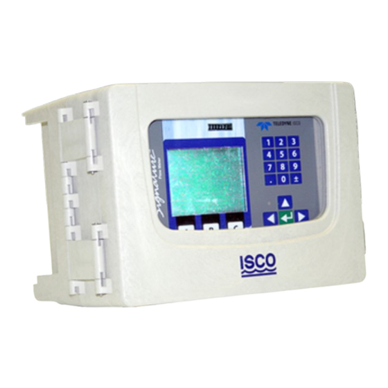
Teledyne TIENet Signature Installation And Operation Manual (207 pages)
Flow Meter Non-Bubbler
Brand:
Teledyne
| Category:
Measuring Instruments
| Size: 5 MB
Table of Contents
Contact Information
3
Table of Contents
7
Signature ® Flow Meter
15
Section 1 Introduction
15
Quick Start
16
Data Integrity
17
Security
17
Compatible Equipment
17
Identifying Signature Components
19
Controls and Indicators
20
Keypad
20
Display and LED
21
Backlight and Screen
21
Display Contrast
21
Technical Specifications
21
Signature Flow Meter Technical Specifications
21
Specification Drawing: Signature Bubbler Flow Meter
26
Signature ® Flow Meter
29
Section 2 Setup and Programming
29
User Interface
29
Keypad Functions
29
Connecting to the Signature with Flowlink
30
Site Info Tab
32
Devices Tab
33
The Home Screen
35
Total Flow
35
Shortcuts
35
Adjust Level
35
Adjust Velocity
35
Purge
35
Histograph
35
Real-Time Measurement
36
Report View
36
Programming
36
Off-Screen Content
36
Character Grid
36
Pull down Menus
37
Program Steps
38
(Menu Trees)
38
Administration Options
38
Smart Sensor Setup (Tienet)
39
Hardware Setup
39
Modbus Input Setup
39
Modbus Output Setup
39
Modem Setup
39
Modbus Input Setup
44
Edit Parameter
45
Configure Options
48
Site Setup
48
Measurement Setup
48
Adjust
48
Equation/Trigger Setup
48
Data Storage/Push Setup
48
Sampler Setup
48
Inputs/Outputs/Alarms Setup
48
Configure Options
52
Measurement Setup
52
Volume Setup
52
Equation/Trigger Setup
53
Example of Defining Conditions & Building Equations
54
SMS and Server Alarm Setup (Modem Required)
57
Reset Totalizers
58
Reports/History Setup
58
Administration
58
Language Options
59
Set New Passcode
59
Update Firmware
59
Sensor Diagnostics
59
Display Signature Information
60
Display License Information
60
Gather Fault Data
60
Restore to Factory Defaults
60
Home
60
USB Options
60
Retrieve Text Reports
61
Retrieve Data
62
Update Firmware
62
Save Current Program
62
Load Existing Program
62
Save Signature Information
62
Gather Fault Data
62
None of the above
62
Signature Data in Flowlink
63
Event Viewer
63
Verifying Exported Reports
64
Section 3 Standard Installation
65
Introduction
65
Connecting External Devices
65
Open Door and Front Panel to Access Interior
66
Connector Case, Connectors, and Fuses
67
Case Bottom Cable Entries
68
Connector Case Cable Entries for Power and External Devices
68
Cable Fittings
69
Strain Relief 3 / 4 NPT Cord-Grip Fitting for Tienet Devices
69
Cord-Grip Fittings Installed
69
Connecting Tienet Devices
71
Tienet Device Terminal Strips
71
Tienet Device Terminal Connections
72
Power
75
Hard Wiring
75
Line Cord
75
Power Connections
75
Mounting the Signature
76
Signature Flow Meter Mounted on Wall
76
Outdoor Recommendations
77
Weather Shield - Recommended for Outdoor Installations
77
Setting the Level
78
Level Adjustment
78
Tienet Sensor Installation in a Hazardous Location
78
Hazardous Location Installation Control Drawing-ATEX
79
Signature ® Flow Meter
81
Section 4 Portable Installation
81
Introduction
81
Portable Stand
81
Adjust Signature to Upward Position
82
Power
84
Power Connections
84
Outdoor Recommendations
84
Battery Installation
85
Battery Life Expectancy
86
Major Standard Equipment Settings Effecting Battery Life
86
Major Optional Equipment Settings Effecting Battery Life
87
Additional Considerations for Battery Life
88
Battery Life Expectancy (Default Measurement Rate of 15 Minutes)
88
Battery Life Expectancy
88
Calculating Average Current Draw
90
Battery Life Calculations
91
Low Battery Cut off and Battery Care
92
Connect to External Devices
93
Connecting Devices to the Tienet Receptacle
93
Section 5 Equipment Options
97
Flow Meter
97
AC Power Cord Kit /AC Wiring (Applies to Permanent Installation Only)
98
Battery Backup (Applies to Permanent Installation Only)
100
Installation
101
Power Loss Alarm
103
Mechanical Totalizer
104
External Desiccator
107
Tienet ® Devices
108
Ultrasonic Level Sensor
108
Bubbler Level Sensor
109
Laser Doppler Velocity Sensor
109
Continuous Wave Doppler Velocity Sensor
109
Sampler Interface
110
Ph and Temperature Device
111
Tienet Expansion Box
111
Contact Output Card
112
(Tienet 304)
112
Configure Options
116
Digital Output Setup
116
Analog Input Card
117
(Tienet 307)
117
Analog Output Card (Tienet 308)
121
ISCO Flowlink Software
125
Ethernet Modem
125
Ethernet Modem Configuration
128
Cellular Modems
130
GSM Modem
130
LTE Modem
131
Installing the Cellular Modem
131
Cellular Modem Configuration
134
Antenna Placement
135
Modem Frequency Bands
136
Section 6 Maintenance and Servicing
137
Maintenance
137
Recommended Maintenance (Accessible Locations)
137
Recommended Maintenance (Difficult-To-Access Locations)
137
Cleaning
138
Firmware Updates
138
Accessing the Interior
140
Desiccant
141
Internal Desiccator
141
External Desiccator
142
Troubleshooting
144
Signature Flow Meter
144
Troubleshooting: Signature Flow Meter
144
Tienet 300 Connector Case
147
Tienet 301 Ph/Temp
147
Troubleshooting: Tienet 300 Connector Case
147
Troubleshooting: Tienet 301 Ph/Temperature Device
147
Teinet 304 Contact Output Card
148
Troubleshooting: Tienet 304 Contact Output Card
148
Tienet 307 Analog Input Card
149
Troubleshooting: Tienet 307 Analog Input Card
149
Tienet 306 Sampler Interface
150
Tienet 308 Analog Output
150
Troubleshooting: Tienet 306 Sampler Interface
150
Troubleshooting: Tienet 308 4-20Ma Analog Output
150
Tienet 310 USLS
151
Troubleshooting: Tienet 310 Ultrasonic Level Sensor
151
Tienet 330 Bubbler
152
Normal Operation
152
Front Cover Replacement
153
System Reset
153
Service and Repair
154
Signature ® Flow Meter
155
Appendix A Replacement Parts
155
How to Order
155
USB Hub
158
Power Supply
159
Circuit Board
160
Appendix B Options and Accessories
165
Ordering Information
165
Signature Flow Meter Accessories
165
Power Accessories
166
Tienet Accessories
166
Internal to Signature
166
Sensor and Cabling
166
Unterminated Leads
167
Tienet Plug
167
Tienet Plug
168
Unterminated Leads
168
Modems
169
Sensor Mounting Rings
169
Spring Rings
169
Scissor Rings
169
Appendix C Modbus Output Protocol
171
Introduction
171
Operation
171
Configurations
172
Glossary of Terms
173
Signature ASCII or RTU Address
174
Register Definitions
174
Modbus Registers
174
Appendix D Material Safety Data Sheets
191
Signature Flow Meter
193
Character Grid
201
Modbus Output Setup
202
Level Adjustment
202
Declaration of Conformity
207
Advertisement
Advertisement
Related Products
Teledyne T200
Teledyne T201
Teledyne T300
Teledyne T300M
Teledyne T320U
Teledyne T360M
Teledyne T3MIL50
Teledyne T3CP50-50
Teledyne T3VNA
Teledyne T3VNA3200
Teledyne Categories
Measuring Instruments
Analytical Instruments
Test Equipment
Digital Camera
Laboratory Equipment
More Teledyne Manuals
Login
Sign In
OR
Sign in with Facebook
Sign in with Google
Upload manual
Upload from disk
Upload from URL