
Subscribe to Our Youtube Channel
Related Manuals for Teledyne T3PM1006


Summary of Contents for Teledyne T3PM1006
- Page 1 T3PM1006 Digital Power Meter User Manual GlobalTestSupply www. .com Find Quality Products Online at: sales@GlobalTestSupply.com...
- Page 2 Teledyne LeCroy company. The information in this manual was correct at the time of printing. However, Teledyne LeCroy continues to improve products and reserves the rights to change specification, equipment, and maintenance procedures at any time without notice.
-
Page 3: Table Of Contents
TABLE OF CONTENTS Table of Contents SAFETY INSTRUCTIONS ..........5 GETTING STARTED ............10 Characteristics ............11 Appearance ..............14 Set Up ................ 23 BASIC SETTING ............. 26 Setting up measurement range ........27 Setting up measurement status ........31 Setting up System status .......... - Page 4 T3PM1006 User Manual Connection Guide ............. 113 CERTIFICATIONS ............115 EMC Compliance ............115 Safety Compliance ............ 117 Environmental Compliance ........118 RESTRICTION OF HAZARDOUS SUBSTANCES (RoHS) ..............118 GlobalTestSupply www. .com Find Quality Products Online at: sales@GlobalTestSupply.com...
-
Page 5: Safety Instructions
Warning: Identifies conditions or practices that WARNING could result in injury or loss of life. Caution: Identifies conditions or practices that CAUTION could result in damage to the T3PM1006 or to other properties. DANGER High Voltage Attention Refer to the Manual Protective Conductor Terminal... - Page 6 T3PM1006 User Manual Safety Guidelines Make sure that the voltage input level does not General Guideline exceed DC848V/AC600V. CAUTION Make sure the current input level does not exceed 20A. Do not place any heavy object on the ...
- Page 7 SAFETY INSTRUCTIONS (Note) EN 61010-1:2010 specifies the measurement categories and their requirements as follows. The T3PM1006 falls under category II 300V. Measurement category IV is for measurement performed at the source of low-voltage installation. Measurement category III is for measurement performed in the building installation.
- Page 8 T3PM1006 User Manual by condensation must be expected. Pollution degree 3: Conductive pollution occurs, or dry, non- conductive pollution occurs which becomes conductive due to condensation which is expected. In such conditions, equipment is normally protected against exposure to direct sunlight, precipitation, and full wind pressure, but neither temperature nor humidity is controlled.
- Page 9 SAFETY INSTRUCTIONS Power cord for the United Kingdom When using the unit in the United Kingdom, make sure the power cord meets the following safety instructions. NOTE: This lead/appliance must only be wired by competent persons WARNING: THIS APPLIANCE MUST BE EARTHED IMPORTANT: The wires in this lead are coloured in accordance with the following code: Green/ Yellow:...
- Page 10 Package Contents ..............13 Appearance ..............14 Front Panel ................14 Display Overview ..............18 Rear Panel ................21 Set Up ................. 23 Tilting the Stand..............23 Power Up .................24 Connect the wires to the T3PM1006 ........25 GlobalTestSupply www. .com Find Quality Products Online at: sales@GlobalTestSupply.com...
-
Page 11: Getting Started
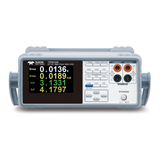
GETTING STARTED Characteristics The T3PM1006 is a high-precision, programmable power meter for measuring low power devices such as switching power supplies, transformers, power supplies, and adapters. It is equipped with a color TFT-LCD screen which is very convenient for reading the measurement results. - Page 12 T3PM1006 User Manual It can even measure the current of abnormal wave of CF 3. The half-range CF is up to 6. Test terminals in the front panel. Total harmonic distortion measurement. Full five-digit measurement. Features ...
-
Page 13: Accessories
GETTING STARTED Accessories Standard Accessories Power Cords x 3 Test leads: 2x red, 2x black Package Contents Check the contents before using the instrument. Opening the box Main unit Power cords x 3 Contents (single unit) Test leads (red x2, Quick Start Guide ... -
Page 14: Appearance
T3PM1006 User Manual Appearance Front Panel LCD display Current input Voltage input Range I - Range MAX Hold CURRENT VOLTAGE Mode Setup Hold AC 10A AC 600V INTEGRATOR Start Stop Reset Local Enter CAT II 300V Key Lock POWER Function... - Page 15 The maximum measurable current and voltage are 600 V and 10A for voltage and current terminals of the front Warning panel of the T3PM1006. Do not input exceeded voltage and current, otherwise it will burn the device. V-Range key, up/down arrow keys...
- Page 16 T3PM1006 User Manual MAX Hold Press this button to display the maximum measurement reading. See page 50. Press this key to select measure Mode mode (DC/AC/AC+DC). See page Press this key to enter the Setup measurement settings menu. See page 31.
- Page 17 GETTING STARTED Press this button to cancel the Cancel (Exit) current setting. The cursor returns to button the default position or return to the previous menu according to the situation. See page 51. These four arrow keys are Arrow Keys used to edit the parameters, browse the menu system and select the parameter...
-
Page 18: Display Overview
T3PM1006 User Manual Display Overview Voltage Range Mode Max. Hold Average Range Current Range Remote Filter KeyLock Display Hold Peak Voltage Peak Current Main Measurement Display Minor Measurement Display Remote Error Secondary Menus Status icon Description Item V_Range 300V Voltage measurement range. - Page 19 GETTING STARTED External current magnification CT Ratio State (on/off) Max. Hold Retain and display the maximum Maximum Hold measurement reading. KeyLock Lock Key button Keyboard Lock Avg-1 Average number of sampling Average (1/2/4/8/16/32/64) Hold Retain and display the current Display Hold measurement reading.
- Page 20 T3PM1006 User Manual System This function key is used to enter the system setting and system configuration screens. GlobalTestSupply www. .com Find Quality Products Online at: sales@GlobalTestSupply.com...
-
Page 21: Rear Panel
GETTING STARTED Rear Panel Current Voltage RS232 USB B input port input port port CURRENT VOLTAGE RS232 600V WARNING TO AVOID SHOCK, CAT II 300V REMOVE INPUTS BEFORE OPENING. GPIB SER.NO. LABEL 240V 50 / 60Hz 25VA MAX AC power input Power Cord Accepts the power cord. - Page 22 The maximum measurable current and voltage are 600 V and 20A for voltage and current terminals of the rear panel of the T3PM1006. Do not input exceeded voltage and current, otherwise it will burn the device. Always use the supplied cable for connection.
-
Page 23: Set Up
GETTING STARTED Set Up Tilting the Stand From the base of the handle, gently pull the handle out sideways and then rotate it to one of the following positions. Horizontal position Tilt stand position Carry position GlobalTestSupply www. .com Find Quality Products Online at: sales@GlobalTestSupply.com... -
Page 24: Power Up
T3PM1006 User Manual Power Up 1. Ensure the AC voltage is 100~ 240V. Steps 2. Connect the power cord to the AC voltage input. Make sure the ground connector on the power Note cord is connected to a safety ground. This will influence the measurement accuracy. -
Page 25: Connect The Wires To The T3Pm1006
GETTING STARTED Connect the wires to the T3PM1006 Two separate wires are used to connect the Background T3PM1006, so voltage and current measurement are isolated and don’t interfere with each other. CURRENT VOLTAGE Connection diagram AC 10A AC 600V CAT II 300V... - Page 26 T3PM1006 User Manual ASIC SETTING Setting up measurement range ........27 Auto Range ................29 Setting up measurement status ........31 Setting up synchronization source .........31 Setting up filter ...............32 Setting up crest factor ............33 Setting up auto-zero function ..........34 Setting up average value ............35 Setting up method of calculating harmonics ......36...
-
Page 27: Basic Setting
BASIC SETTING Setting up measurement range To get accurate measurement results, set an appropriate measurement range before performing measurements. Set voltage range 1. Press V-Range button. V - Range 2. Use up and down arrow keys to select the desired range. 3. - Page 28 T3PM1006 User Manual 2. Use up and down arrow keys to select the desired range. 3. Press Enter button to confirm your Enter selection. Available range Crest Factor AUTO, 5mA, 10mA, 20mA, 50mA, is 3: 100mA, 200mA, 0.5A, 1A, 2A, 5A,10A, Crest Factor AUTO, 2.5mA, 5mA, 10mA, 25mA,...
-
Page 29: Auto Range
BASIC SETTING The P.V status icon lights in red when the voltage Note measurement circuit detects that the measured value exceeds setting range by 3 folds (CF is set to 3) or 6 folds (CF is set to 6). Auto Range The range is automatically switched according to the voltage and current of input signal. - Page 30 T3PM1006 User Manual Example Irms exceeds the current setting range by 110%, so range is shifted to 20mA Irms is less than or equal to 60% of the previous setting range, so range is shifted down to 10mA. GlobalTestSupply www.
-
Page 31: Setting Up Measurement Status
BASIC SETTING Setting up measurement status Setting up synchronization source 1. Press Setup button. Setup Steps 2. Press Enter button. Enter 3. Press down arrow key. 4. Press Enter button to enter Sync Enter Source item. Use up and down arrow keys to select the desired option and then press Enter button again to confirm your selection. -
Page 32: Setting Up Filter
T3PM1006 User Manual Setting up filter 1. Press Setup button. Steps Setup 2. Press Enter button. Enter 3. Press down arrow key twice. 4. Press Enter button to enter Filter Enter item. Use up and down arrow keys to select the desired option and then press Enter button again to confirm your selection. -
Page 33: Setting Up Crest Factor
BASIC SETTING Setting up crest factor 1. Press Setup button. Steps Setup 2. Press Enter button. Enter 3. Press down arrow key three times. 4. Press Enter button to enter Crest Enter Factor item. Use up and down arrow keys to select the desired option and then press Enter button again to confirm your selection. -
Page 34: Setting Up Auto-Zero Function
T3PM1006 User Manual Setting up auto-zero function 1. Press Setup button. Steps Setup 2. Press Enter button. Enter 3. Press down arrow key four times. 4. Press Enter button to enter Auto Enter Zero item. Use up and down arrow... -
Page 35: Setting Up Average Value
BASIC SETTING Setting up average value 1. Press Setup button. Steps Setup 2. Press Enter button. Enter 3. Press down arrow key five times. 4. Press Enter button to enter Average Enter item. Use up and down arrow keys to select the desired option and then press Enter button again to confirm your selection. -
Page 36: Setting Up Method Of Calculating Harmonics
T3PM1006 User Manual Setting up method of calculating harmonics 1. Press Setup button. Steps Setup 2. Press Enter button. Enter 3. Press down arrow key six times. 4. Press Enter button to enter Enter Harmonics item. Use up and down... -
Page 37: Setting Up The Pt Ratio Status
BASIC SETTING Setting up the PT ratio status 1. Press Setup button. Steps Setup 2. Press Enter button. Enter 3. Press down arrow key seven times. 4. Press Enter button to enter PT Enter Ratio Status item. Use up and down arrow keys to select the desired option and then press Enter button again to confirm your... -
Page 38: Setting Up The Ct Ratio Status
T3PM1006 User Manual Setting up the CT ratio status 1. Press Setup button. Steps Setup 2. Press Enter button. Enter 3. Press down arrow key eight times. 4. Press Enter button to enter CT Enter Ratio Status item. Use up and... -
Page 39: Setting Up The Voltage And Current Skipping Configuration
BASIC SETTING Setting up the voltage and current skipping configuration 1. Press Setup button. Steps Setup 2. Press right arrow key to enter SETUP1 tab. Enter 3. Press Enter button. 4. Press down arrow key to enter the V/I-Range Skipping Config. Enter 5. - Page 40 T3PM1006 User Manual 7. Press Enter button to confirm Enter setting. 8. Press up, down, right and left arrow keys to move cursor to V- Range and I-Range fields where options are available for user to enable or disable for measurement.
-
Page 41: Setting Up System Status
BASIC SETTING Setting up System status System configuration setting screen 1. Use left and right arrow keys on Steps the front panel to select System function key. 2. Press Enter button to Enter Enter SYSTEM INFORMATION setting screen. 3. Press right arrow key to select Config key. -
Page 42: Setting Up Brightness
T3PM1006 User Manual 2. Press Enter button to enter Power Enter On Status Setup item. Use up and down keys to select the desired option and then press Enter button again to confirm your selection. Enter Option Previous: The status of device on powering on is set to the status before the last shutdown. -
Page 43: Setting Up Key Sound
BASIC SETTING 2. Press Enter button to enter Enter Brightness item. Use up and down keys to select a number and then press Enter button again to confirm your selection. Enter Option 1 to 9 The display is the darkest when set to 1. -
Page 44: Setting Up Interface
T3PM1006 User Manual 2. Press Enter button to enter Key Enter Sound item. Use up and down arrow keys to select the desired option and then press Enter button again to confirm your selection. Enter Option A short sound is heard from the speaker of device when pressing the keys on the front panel. - Page 45 BASIC SETTING 2. Press Enter button to enter I/O Enter Model item. Use up and down arrow keys to select the desired option and then press Enter button again to confirm your selection. Enter Option RS232: If interface is set to RS232, the Baud Rate can be selected from the following options.
-
Page 46: Measurement And Other Functions
T3PM1006 User Manual EASUREMENT AND OTHER FUNCTIONS Measurement function ..........47 Introduction to measurement parameters ......47 Setting measurement parameters ..........48 Other functions ............50 Introduction to other functions ..........50 Integration measurement function ......52 Setting up Integrator measurement ........52 Introduction to integrator parameters ........55 Using the integrator function ..........57... -
Page 47: Measurement Function
MEASUREMENT AND OTHER FUNCTIONS Measurement function The T3PM1006 provides a wide range of basic electricity and power measurement functions. It is equipped with different accurate measurement parameters for accurately measuring the voltage, current, power, DC/AC/AC + DC, power factor, harmonics, frequency, etc. -
Page 48: Setting Measurement Parameters
T3PM1006 User Manual P+pk and P-pk Active Power Peak THDI and THDV Total Harmonic Distortion CFV, CFI Crest factor Setting measurement parameters Please follow the steps blow to set the measurement parameters 1. Use left and right arrow keys on... - Page 49 MEASUREMENT AND OTHER FUNCTIONS 5. In standard display mode, you Switching display Enter simply press the Enter button to mode switch display mode to simple. 6. Press ESC button to return back to original display mode. GlobalTestSupply www. .com Find Quality Products Online at: sales@GlobalTestSupply.com...
-
Page 50: Other Functions
T3PM1006 User Manual Other functions Introduction to other functions Mode Max. Hold KeyLock Display Hold Function name Button Description When the MAX Hold button is MAX Hold MAX Hold pressed, the MAX Hold status icon will light in red in the LCD display to indicate that this function is activated. - Page 51 MEASUREMENT AND OTHER FUNCTIONS Mode Press this button to select Mode measurement mode. There are 3 measurement modes. AC+DC: Displays all the components of the measurement signal DC: Displays the DC part of the measurement signal. AC: Displays the AC part of the ...
-
Page 52: Integration Measurement Function
T3PM1006 User Manual Integration measurement function Setting up Integrator measurement 1. Use left and right arrow keys on Steps the front panel to select Integrator function key. 2. Press Enter button to enter the Enter integrator measurement screen. 3. Press right arrow key to select Set key. - Page 53 MEASUREMENT AND OTHER FUNCTIONS 4. Press Enter button to enter Select integrator Enter integrator measurement setting measurement mode screen. 5. Press Enter button to enter Mode Enter item. Use up and down arrow keys to toggle between Manual and Standard mode. Press Enter button again to confirm your selection.
- Page 54 T3PM1006 User Manual If you select standard mode, you need to set integrator measurement time before using integrator function. It can be set from 1 second to 9999 hours, 59 minutes and 59 seconds. 6. Press down arrow key to select Function item in the integrator measurement setting screen.
-
Page 55: Introduction To Integrator Parameters
MEASUREMENT AND OTHER FUNCTIONS Introduction to integrator parameters Parameter name Description Manual Mode Standard Watt Hours Function WP: Total power WP+: Positive total power WP-: Negative total power Ampere Hours q: Total mAh q+: Positive total q-: Negative total It indicates the time of integrator measurement to Set time... - Page 56 T3PM1006 User Manual Running State Integrator measurement is in progress. Stop Integrator measurement has been stopped manually. Timeout The time for running integrator measurement is up. Reset The integrator measurement status is cleared. ...
-
Page 57: Using The Integrator Function
MEASUREMENT AND OTHER FUNCTIONS Using the integrator function 1. In manual mode, you can directly INTEGRATOR Manual mode Start press the Start button in the front panel to start integrator function. 2. To stop integration function, press Stop the Stop button in the front panel. 3. - Page 58 T3PM1006 User Manual 1. Set integrator measurement time before using Standard mode integrator function. 2. Other steps are the same as running in manual mode. When integrator is running, the test time will increase until the setting integrator measurement time.
-
Page 59: Remote Control
REMOTE CONTROL EMOTE CONTROL This chapter describes basic configuration of IEEE488.2 based remote control. For a command list, refer to the Command Overview chapter on page 64. Configure Remote Control Interface ......60 USB Interface ................. 60 Configure USB Interface ............60 Configure RS232 Interface ............. -
Page 60: Configure Remote Control Interface
The USB device port on the rear panel is used for remote control. The USB port is configured as CDC interface. When configured to CDC, the USB port on the T3PM1006 will appear as a virtual COM port to a connected PC. Any terminal program that can communicate via a serial port can be used for remote control. - Page 61 Pin 5: GND Pin 1, 4, 6 ~ 9: No 6 7 8 9 Connection Use a Null Modem connection as shown in the PC Connection diagram below. T3PM1006 Pin2 RxD Pin2 Pin3 TxD Pin3 Pin5 GND Pin5 Configure LAN Interface...
- Page 62 T3PM1006 User Manual 3. Select a desired IP Model. Option Manual Set up IP Address, Subnet mask and Gateway manually. DHCP DHCP server automatically assigns IP Address, Subnet mask and Gateway. GlobalTestSupply www. .com Find Quality Products Online at: sales@GlobalTestSupply.com...
-
Page 63: Return To Local Control
REMOTE CONTROL Return to Local Control When the unit is in remote control mode, the Background RMT icon above the main display can be seen. When this icon is not displayed, it indicates that the unit is in local control mode. 1. -
Page 64: Command Overview
T3PM1006 User Manual OMMAND OVERVIEW The Command overview chapter lists all programming commands in functional order as well as alphabetical order. The command syntax section shows you the basic syntax rules you have to apply when using commands. Command Syntax... - Page 65 COMMAND OVERVIEW There are a number of different instrument Command Types commands and queries. A command sends instructions or data to the unit and a query receives data or status information from the unit. Command types A single command Simple with/without a parameter :INPut:MODE DC Example...
- Page 66 T3PM1006 User Manual Commands that contain square brackets Square Brackets indicate that the contents are optional. The function of the command is the same with or without the square bracketed items, as shown below. For example, for the query: [:INPut]:FILTer? Both :INPut:FILTer? and :FILTer? are valid forms.
- Page 67 COMMAND OVERVIEW For commands, this will set the [MAX] (Optional setting to the highest value. This parameter) parameter can be used in place of any numerical parameter where indicated. For queries, it will return the highest possible value allowed for the particular setting.
-
Page 68: Command List
T3PM1006 User Manual Command List SCPI Commands *CLS ................70 *IDN ................70 *ESE ................70 *ESR ................71 *OPC ................71 *RST ................71 *SRE ................72 *STB ................72 COMMunciate :COMMunicate:HEADer ..........73 Commands :COMMunicate:REMote ..........73 :COMMunicate:VERBose ..........74 DISPlay :DISPlay[:NORMal]:ITEM<x>... - Page 69 COMMAND OVERVIEW [:INPut]:ZERO ..............86 INTegrate :INTegrate:MODE ............87 commands :INTegrate:FUNCtion ..........87 :INTegrate:TIMer ............88 :INTegrate:STARt ............88 :INTegrate:STOP ............88 :INTegrate:RESet ............88 :INTegrate:STATe ............89 MEASure :MEASure:AVERaging:COUNt ........90 commands :MEASure:MHOLd ............90 NUMeric :NUMeric[:NORMal]:VALue ........91 commands :NUMeric[:NORMal]:NUMBer ........92 :NUMeric[:NORMal]:ITEM<x> ........92 :NUMeric[:NORMal]:PRESet ........94 :NUMeric[:NORMal]:CLEar .........96 :NUMeric[:NORMal]:DELete ........97 :NUMeric[:NORMal]:HEADer ........97 SYSTem :SYSTem:MODel ............98...
-
Page 70: Scpi Commands *Cls
T3PM1006 User Manual SCPI Commands *CLS ................70 *IDN ................70 *ESE ................70 *ESR ................71 *OPC ................71 *RST ................71 *SRE ................72 *STB ................72 *CLS Clears the Event Status register (Output Queue, Description Operation Event Status, Standard Event Status). -
Page 71: Esr
COMMAND OVERVIEW Parameter/ 0~255 <NR1> Return parameter Example *ESE 65 Set the ESER to 01000001 *ESE? ->130 ESER=10000010 *ESR Query Returns SESR (Standard Event Status Register). Description Query Syntax *ESR? Return parameter <NR1> 0~255 Example *ESR? ->198 SESR=11000110 *OPC Query Sets or returns the operation complete bit (bit0) in Description SERS (Standard Event Status Register) when all... -
Page 72: Sre
T3PM1006 User Manual *SRE Query Sets or returns SRER (Service Request Enable Description Register) Syntax *SRE <NR1> Query Syntax *SRE? Parameter/ 0~255 <NR1> Return parameter Example *SER 7 Set the the SRER to 00000111 *SRE? ->3 SRER=00000011 *STB Query Returns the SBR (Status Byte Register) contents. -
Page 73: Communicate:header
Example of a response with a header :INPUT:VOLTAGE:RANGE 150.0E+00 Example of a response without a header 150.0E+00 :COMMunicate:REMote Query Sets or returns the T3PM1006 to remote or local Description mode. ON is remote mode. Syntax :COMMunicate:REMote <Boolean>|{OFF | ON} Query Syntax... -
Page 74: Communicate:verbose
T3PM1006 User Manual Parameter <Boolean>0 OFF <Boolean>1 ON Return parameter 0 Turn the remote function off Turn the remote function on Example :COMMUNICATE:REMOTE ON :COMMUNICATE:REMOTE? ->:COMMUNICATE:REMOTE 1 :COMMunicate:VERBose Query Sets or returns whether the response to a query is Description returned fully spelled out or in its abbreviated form. -
Page 75: Display[:Normal]:Item
1 to 8 (display) Return parameter <Function> {U|UPPeak|UMPeak|I|IPPeak|IMPeak |P|PPPeak|PMPeak|S|Q|LAMBda|CFU |CFI|PHI|FU|FI|UTHD|ITHD} Example :DISPLAY:NORMAL:ITEM1 U :DISPLAY:NORMAL:ITEM1? ->:DISPLAY:NORMAL:ITEM1 U <Function> Function T3PM1006 Indicator Voltage U UPPeak Maximum voltage: U+pk [V+pk] UMPeak Minimum voltage: U-pk [V-pk] Current I IPPeak Maximum current: I+pk [I+pk] IMPeak... -
Page 76: Display:integrate:item
T3PM1006 User Manual Reactive power Q [VAR] LAMBda Power factor λ [PF] Voltage factor λ [CFV] Current factor λ [CFI] Phase difference Φ [DEG] Voltage frequency fu [VHz] Current frequency fI [AHz] UTHD Total harmonic distortion of [THDV] voltage Uthd... -
Page 77: Display:page
COMMAND OVERVIEW :DISPlay:PAGE Query Sets or returns the display page item. Description Syntax :DISPlay:PAGE <Function> Query Syntax :DISPlay:PAGE? Parameter/ <Function> {MEASurement|ENLArge|INTEgral| SYSTem_INFO|SYSTem_CONFig|SETUp} Return parameter Example :DISPLAY:PAGE MEASUREMENT :DISPLAY:PAGE? ->:DISPLAY:PAGE MEASUREMENT GlobalTestSupply www. .com Find Quality Products Online at: sales@GlobalTestSupply.com... -
Page 78: Harmonics:thd
T3PM1006 User Manual HARMonics Command :HARMonics:THD Query Sets or returns the equation used to compute the Description THD (total harmonic distortion). Syntax :HARMonics:THD {TOTal|FUNDamental} Query Syntax :HARMonics:THD? Parameter/ TOTal (CSA) FUNDamental (IEC) Return parameter Example :HARMONICS:THD FUNDAMENTAL :HARMONICS:THD? ->:HARMONICS:THD FUNDAMENTAL GlobalTestSupply www. -
Page 79: Hold Command :Hold
COMMAND OVERVIEW HOLD Command :HOLD Query Sets or returns the on/off state of the output hold Description feature for display, communication, and other types of data. Syntax :HOLD <Boolean>|{OFF|ON} Query Syntax :HOLD? Parameter <Boolean>0 <Boolean>1 Return parameter 0 Turn the hold function off Turn the hold function on Example :HOLD OFF... -
Page 80: [:Input]:Cfactor
T3PM1006 User Manual INPut Commands [:INPut]:CFACtor ............80 [:INPut]:MODE ............80 [:INPut]:VOLTage:RANGe ........... 81 [:INPut]:VOLTage:AUTO ..........81 [:INPut]:VOLTage:CONFig .......... 82 [:INPut]:CURRent:RANGe ........... 82 [:INPut]:CURRent:AUTO ..........83 [:INPut]:CURRent:CONFig .......... 83 [:INPut]:RCONfig ............84 [:INPut]:SCALing:{VT/PT|CT}:STATe ......84 [:INPut]:SCALing:{VT/PT|CT}:RATio ......85 [:INPut]:SYNChronize..........85 [:INPut]:FILTer ............. -
Page 81: [:Input]:Voltage:range
COMMAND OVERVIEW Parameter/ Select the dc measurement mode. Return parameter Select the acdc measurement mode. Select the ac mode. Example :INPUT:MODE DC :INPUT:MODE? ->:INPUT:MODE DC [:INPut]:VOLTage:RANGe Query Sets or returns the voltage range. Description Syntax [:INPut]:VOLTage:RANGe {<Voltage>} Query Syntax [:INPut]:VOLTage:RANGe? Parameter/ <Voltage>... -
Page 82: [:Input]:Voltage:config
T3PM1006 User Manual Example :INPUT:VOLTAGE:AUTO ON :INPUT:VOLTAGE:AUTO? ->:INPUT:VOLTAGE:AUTO 1 [:INPut]:VOLTage:CONFig Query Sets or returns the valid voltage range. Description Syntax [:INPut]:VOLTage:CONFig {ALL|<Voltage>[,Voltage]…} Query Syntax [:INPut]:VOLTage:CONFig? Parameter/ All ranges are valid. Return parameter <Voltage> See(:INPut:VOLTage:RANGe). Example :INPUT:VOLTAGE:CONFIG 300,150,30 :INPUT:VOLTAGE:CONFIG? ->:INPUT:VOLTAGE:CONFIG 300.0E+00,150.0E+00, 30.0E+00... -
Page 83: [:Input]:Current:auto
COMMAND OVERVIEW [:INPut]:CURRent:AUTO Query Sets or returns the current auto range on/off state. Description Syntax [:INPut]:CURRent:AUTO {<Boolean>} Query Syntax [:INPut]:CURRent:AUTO? Parameter <Boolean>0 OFF <Boolean>1 ON Return parameter 0 Turn the current auto range function off. Turn the current auto range function on. Example :INPUT:CURRENT:AUTO ON :INPUT:CURRENT:AUTO? -
Page 84: [:Input]:Rconfig
T3PM1006 User Manual [:INPut]:RCONfig Query Sets or returns the on/off state of the range Description configuration (valid range selection) feature. Syntax [:INPut]:RCONfig {<Boolean>|OFF|ON} Query Syntax [:INPut]:RCONfig? Parameter <Boolean>0 OFF <Boolean>1 ON Return parameter 0 Turn the range configuration feature off. -
Page 85: [:Input]:Scaling:{Vt/Pt|Ct}:Ratio
COMMAND OVERVIEW [:INPut]:SCALing:{VT/PT|CT}:RATio Query Collectively Sets or returns the vt/pt ratio or ct Description ratio. Syntax [:INPut]:SCALing:{VT/PT|CT|}:RATio {<NRf>} Query Syntax [:INPut]:SCALing:{VT/PT|CT}: RATio? Parameter/ <NRf> 1.000 to 9999.999 Return parameter Example :INPUT:SCALING:VT:RATIO 1 :INPUT:SCALING:VT:RATIO? ->:INPUT:SCALING:VT:RATIO 1 [:INPut]:SYNChronize Query Sets or returns the synchronization source. Description Syntax [:INPut]:SYNChronize {VOLTage|CURRent|OFF}... -
Page 86: [:Input]:Zero
T3PM1006 User Manual Parameter <Boolean>0 OFF <Boolean>1 ON Return parameter 0 Turn the filter function off. Turn the filter function on. Example :INPUT:FILTER OFF :INPUT:FILTER? ->:INPUT:FILTER 0 [:INPut]:ZERO Query Sets or returns the zero state. Description Syntax [:INPut]:ZERO {<Boolean>} Query Syntax... -
Page 87: Integrate :Integrate:mode
COMMAND OVERVIEW INTegrate Commands :INTegrate:MODE ............87 :INTegrate:FUNCtion ..........87 :INTegrate:TIMer ............88 :INTegrate:STARt ............88 :INTegrate:STOP ............88 :INTegrate:RESet ............88 :INTegrate:STATe ............89 :INTegrate:MODE Query Sets or returns the integration mode. Description Syntax :INTegrate:MODE {MANUal | STANdard} Query Syntax :INTegrate:MODE? Parameter/ MANUal Continuous integration mode. Return parameter STANdard Standard integration mode. -
Page 88: Integrate:timer
T3PM1006 User Manual :INTegrate:TIMer Query Sets or returns the integration timer value. Description Syntax :INTEGrate:TIMer {<NRf>,<NRf>,<NRf>} Query Syntax :INTEGrate:TIMer? Parameter/ {<NRf>,<NRf>,<NRf>} 0,0,0 to 9999,59,59 Return parameter First <NRf> 0 to 9999 (hours) Second <NRf> 0 to 59 (minutes) Third <NRf>... -
Page 89: Integrate:state
COMMAND OVERVIEW :INTegrate:STATe Query Queries the integration status. Description Syntax :INTegrate:STATe? Example :INTEGRATE:STATE? ->RESET Response Overflow Integration overflows. RESET Integration resets. RUNNING Integration is in progress. STOP Integration stops. TIMEUP Integration stops due to integration timeout. GlobalTestSupply www. .com Find Quality Products Online at: sales@GlobalTestSupply.com... -
Page 90: Measure :Measure:averaging:count
T3PM1006 User Manual MEASure Commands :MEASure:AVERaging:COUNt ........90 :MEASure:MHOLd ............90 :MEASure:AVERaging:COUNt Query Sets or returns the averaging coefficient. Description Syntax :MEASure:AVERaging:COUNt {<NRf>} Query Syntax :MEASure:AVERaging:COUNt? Parameter/ <NRf> 1, 2, 4, 8, 16, 32, 64 Return parameter Example :MEASURE:AVERAGING:COUNT 8 :MEASURE:AVERAGING:COUNT? ->:MEASURE:AVERAGING:COUNT 8... -
Page 91: Numeric :Numeric[:Normal]:Value
COMMAND OVERVIEW NUMeric Commands :NUMeric[:NORMal]:VALue ........91 :NUMeric[:NORMal]:NUMBer ........92 :NUMeric[:NORMal]:ITEM<x> ........92 :NUMeric[:NORMal]:PRESet ........94 :NUMeric[:NORMal]:CLEar .........96 :NUMeric[:NORMal]:DELete ........97 :NUMeric[:NORMal]:HEADer ........97 :NUMeric[:NORMal]:VALue Query Returns the numeric data. Description Syntax :NUMeric[:NORMal]:VALue? Example :NUMERIC:NORMAL:VALUE? -> 103.79E+00,1.0143E+00,105.27E+00,..(omitted)..,50.0 01E+00 Measurement values U, I, P, PPPeak, PMPeak, S, Numeric Data Format Q, LAMBda, CFU, CFI, FU, FI, UTHD and ITHD... -
Page 92: Commands :Numeric[:Normal]:Number
T3PM1006 User Manual Elapsed integration time (TIME) ASCII: <NR1> format in units of seconds. Example: 3600 for 1 hour (1:00:00). No items (“-----”) ASCII: NAN (Not A Number) Data does not exist (the display shows “-----”) Error Data... - Page 93 Return parameter <Function> {U|UPPeak|UMPeak|I|IPPeak|IMPeak |P|PPPeak|PMPeak|S|Q|LAMBda|CFU |CFI|PHI|FU|FI|UTHD|ITHD|WH |WHP|WHM|AH|AHP|AHM|TIME |URANge|IRANge} Example :NUMERIC:NORMAL:ITEM1 U :NUMERIC:NORMAL:ITEM1? ->:NUMERIC:NORMAL:ITEM1 U <Function> Function T3PM1006 Indicator Voltage U UPPeak Maximum voltage: U+pk [V+pk] UMPeak Minimum voltage: U-pk [V-pk] Current I IPPeak Maximum current: I+pk [I+pk] IMPeak Minimum current: I-pk...
-
Page 94: Numeric[:Normal]:Preset
T3PM1006 User Manual ITHD Total harmonic distortion of [THDI] current Ithd Watt hour WP [WP] Positive watt hour WP+ [WP+] Positive watt hour WP- [WP-] Ampere hour q Positive ampere hour q+ [q+] Positive ampere hour q [q-] TIME Integration time... - Page 95 COMMAND OVERVIEW Patterns 3 ITEM<x> <Function> LAMBda UPPeak UMPeak IPPeak IMPeak PPPeak PMPeak Patterns 4 ITEM<x> <Function> LAMBda GlobalTestSupply www. .com Find Quality Products Online at: sales@GlobalTestSupply.com...
-
Page 96: Numeric[:Normal]:Clear
T3PM1006 User Manual UPPeak UMPeak IPPeak IMPeak TIME PPPeaK PMPeaK UTHD ITHD URANge IRANge :NUMeric[:NORMal]:CLEar Clears numeric data output items (sets the items to Description “-----“). Syntax :NUMeric[:NORMal]:CLEar {ALL|<NRf>[,<NRf>]} Parameter First <NRf> 1 to 34 (the number of the first item to clear) Second <NRf>... -
Page 97: Numeric:normal:delete
COMMAND OVERVIEW Note If the 2nd <NRf> is omitted, the output item specified by the first and all following output items (up to number 34) are cleared. :NUMeric[:NORMal]:DELete Deletes numeric data output items. Description Syntax :NUMeric[:NORMal]:DELete {ALL|<NRf>[,<NRf>]} Parameter First <NRf> 1 to 34 (the number of the first item to delete) Second <NRf>... -
Page 98: System :System:model
T3PM1006 User Manual SYSTem Commands :SYSTem:MODel............98 :SYSTem:SERial ............98 :SYSTem:VERSion............98 :SYSTem:KLOCk ............99 :SYSTem:BRIGhtness ..........99 :SYSTem:KEY:BEEPer ..........100 :SYSTem:MODel Query Returns the model code. Description Syntax :SYSTem:MODel? Example :SYSTEM:MODEL? ->:SYSTEM:MODEL "T3PM1006" :SYSTem:SERial Query Returns the serial number. -
Page 99: System:klock
COMMAND OVERVIEW Note Returns the Ver. item string of the system Information menu. :SYSTem:KLOCk Query Sets or returns the on/off state of the key Description protection. Syntax :SYSTem:KLOCk {<Boolean>} Query Syntax :SYSTem:KLOCk? Parameter <Boolean> 0 <Boolean> 1 Return parameter 0 Turn the key protection function off Turn the key protection function on. -
Page 100: System:key:beeper
T3PM1006 User Manual :SYSTem:KEY:BEEPer Query Sets or returns the keyclick beeper state. Description Syntax :SYSTem:KEY:BEEPer {<Boolean>} Query Syntax :SYSTem:COMMunicate:LAN:CONFigure? Parameter <Boolean> 0 <Boolean> 1 Return parameter 0 Turn the keyclick beeper function off. Turn the keyclick beeper function on. Example... -
Page 101: Status Command :Status:error
COMMAND OVERVIEW STATus Command :STATus:ERRor Query Queries the error code and message of the last Description error that has occurred (top of the error queue). Query Syntax :STATus:ERRor? Example :STATUS:ERROR? -> Error_103:Invalid separator If no errors have occurred, 0,”No error” is Note returned. -
Page 102: Appendix
T3PM1006 User Manual PPENDIX Specifications ............103 General Specifications ............103 Input ..................104 Display...................104 Voltage Measurement ............105 Current Measurement ............105 Power Measurement .............106 Frequency Measurement ............106 Integrator Measurement ............106 Dimensions .............. 108 Power measurement ..........109 Measurement for small current ...........109 Measurement for large current ..........110... -
Page 103: Specifications
APPENDIX Specifications Below are the basic conditions required to operate the T3PM1006 within specification: Calibration: Yearly 18~28 ˚C (64.4~82.4˚F) Operating Environment: Humidity: <80%RH, Accuracy: ± (% of reading + % of range) The specifications apply when the unit is warmed up for at least ... -
Page 104: Input
T3PM1006 User Manual Input Item Spec. Input voltage 600 Vrms Input current 20 Arms Voltage 2.4MΩ Input 5mA - 200mA 500mΩ impedance(50/60 Hz) Current 0.5A - 20A 5mΩ Maximum display voltage 700 Vrms* Maximum display current 25 Arms* Maximum allowable isolation voltage... -
Page 105: Voltage Measurement
APPENDIX Vdc, Vrms, V+pk, V-pk, Idc, Irms, Displayed measurement I+pk, I-pk, P, P+pk, P-pk, VA, VAR, parameters PF, CFV, CFI, DEG, VHz, IHz, THDV, THDI Voltage Measurement CF=3 : 15V, 30V, 60V, 150V, 300V, 600V Measurement range CF=6 : 7.5V, 15V, 30V, 75V, 150V, 300V Crest factor 3, 6 Effective range... -
Page 106: Power Measurement
T3PM1006 User Manual The filter is turned Increase 0.3 % reading@ 45Hz to 66Hz Temperature 5-18˚C / 28-40˚C Increase ±0.03% reading /˚C effect Residual noise 0.5 % of range Power Measurement Effective range 1 % to 110 % of range ±(0.2 % reading + 0.2 % range) - Page 107 APPENDIX accordingly, the value acquired from other instruments, which employ different methods, may differ from that acquired from T3PM1006 unit. * “Zero” will be shown for S or Q and “--“ will be displayed for λ and Φ when either current or voltage is less than 0.5% of the rated range (less than or equivalent to 1% when crest factor is set 6).
-
Page 108: Dimensions
T3PM1006 User Manual Dimensions Units = mm GlobalTestSupply www. .com Find Quality Products Online at: sales@GlobalTestSupply.com... -
Page 109: Power Measurement
APPENDIX Power measurement Direct read method: Directly read the Method measurement value measured from power measuring instrument. The average power method: Record the actual power value within a settable period of time and then take the average. A settable period of time isn’t less than 10min. -
Page 110: Measurement For Large Current
T3PM1006 User Manual Measurement for large current Voltage measurement mode measured from load side (Connect to ammeter externally). The voltage measurement is accurate. The current measurement on load could be larger than the actual one due to leakage current of multi-measurement voltage. -
Page 111: Introduction To Iec-62301
Over-range automatic alarm function is available. Turning off the auto range function is available. Harmonic bandwidth is greater than or equal to 2.5kHz. The T3PM1006 meets all of the features listed above. GlobalTestSupply www. .com Find Quality Products Online at: sales@GlobalTestSupply.com... -
Page 112: Eup Directive Lot6 Specifications
T3PM1006 User Manual EUP Directive Lot6 specifications Ecodesign directive for energy-using products: The power loss requirement for the products with external power supply such as information devices, consumer electronics product, household appliances, toys, entertainment and sports products and so on in standby and off mode is as below. -
Page 113: Connection Guide
APPENDIX Connection Guide Front panel Lower current measurement: I < 1A SOURCE LOAD Method 1 CURRENT VOLTAGE SOURCE LOAD AC 10A AC 600V CAT II 300V SOURCE LOAD Method 2 CURRENT VOLTAGE SOURCE LOAD AC 10A AC 600V CAT II 300V Higher current measurement: 1A <... -
Page 114: Rear Panel
T3PM1006 User Manual SOURCE LOAD Method 2 CURRENT VOLTAGE SOURCE LOAD AC 10A AC 600V CAT II 300V Rear panel Direct connection: 10A < I < 20A SOURCE LOAD CURRENT VOLTAGE RS232 SOURCE LOAD 600V WARNING TO AVOID SHOCK, CAT II 300V REMOVE INPUTS BEFORE OPENING. -
Page 115: Certifications
CERTIFICATIONS ERTIFICATIONS Teledyne LeCroy certifies compliance to the following standards as of the time of publication. Please see the EC Declaration of Conformity document shipped with your product for current certifications. EMC Compliance EC DECLARATION OF CONFORMITY - EMC The instrument meets intent of EC Directive 2014/30/EU for Electromagnetic Compatibility. - Page 116 T3PM1006 User Manual EN 61000-4-4:2012 Electrical Fast Transient/Burst, 1 kV on power supply lines, 0.5 kV on I/O signal data and control lines EN 61000-4-5:2014+A1:2017 Power Line Surge, 1 kV AC Mains, L-N, L-PE, N-PE EN 61000-4-6:2014 RF Conducted Electromagnetic Field, 3 Vrms, 0.15 MHz - 80 MHz...
-
Page 117: Safety Compliance
CERTIFICATIONS AS/NZS CISPR 11:2015 Radiated and Conducted Emissions, Group 1, Class A. Australia / New Zealand Contacts:* RS Components Pty Ltd. RS Components Ltd. Suite 326 The Parade West Units 30 & 31 Warehouse World Kent Town, South Australia 5067 761 Great South Road Penrose, Auckland, New Zealand Safety Compliance EC DECLARATION OF CONFORMITY –... -
Page 118: Environmental Compliance
T3PM1006 User Manual • Unit: Pollution Degree 2, operating environment where normally only dry, non-conductive pollution occurs. Temporary conductivity caused by condensation should be expected. Environmental Compliance END-OF-LIFE HANDLING The instrument is marked with this symbol to indicate that it complies with the applicable European Union... - Page 119 CERTIFICATIONS limits for certain restricted substances in electrical and electronic products). The instrument is marked with an appropriate Environmental Friendly Use Period (EFUP) symbol. The packaging materials include the appropriate recycling labels. The below substance disclosure tables (in Chinese and English languages) provide the required compliance information.
- Page 120 T3PM1006 User Manual Toxic or Hazardous Substances and Elements Lead Mercury Cadmium Hexavalent Polybrominated Polybrominated Part Name (Pb) (Hg) (Cd) Chromium Biphenyls Diphenyl Ethers (Cr6+) (PBB) (PBDE) PCBAs Mechanical Hardware Sheet Metal Plastic Parts Cable Assemblies Display Power Supply Fans...
- Page 121 Distributed by: © 2020 Teledyne Test Tools is a brand and trademark of Teledyne LeCroy Inc. All rights reserved. Specifications, prices, availability and delivery subject to change without notice. Product brand or brand names are trademarks or requested trademarks of their respective holders.
Need help?
Do you have a question about the T3PM1006 and is the answer not in the manual?
Questions and answers