Eaton ATC-300+ Operation And Maintenance Manual
Automatic transfer switch controller
Hide thumbs
Also See for ATC-300+:
- O & m manual (40 pages) ,
- Instruction sheet (9 pages) ,
- Setup instructions (11 pages)
Table of Contents
Advertisement
Instruction Booklet IB01602009EN
Automatic Transfer Switch Controller, ATC-300+
operation and maintenance manual
Contents
Description
1. Introduction . . . . . . . . . . . . . . . . . . . . . . . . . . . . . . .2
2. Hardware description . . . . . . . . . . . . . . . . . . . . . . .6
3. Status monitoring and setpoints . . . . . . . . . . . 10
5 Operation . . . . . . . . . . . . . . . . . . . . . . . . . . . . . . . . 14
6. Programming . . . . . . . . . . . . . . . . . . . . . . . . . . . . 17
7. Troubleshooting and maintenance . . . . . . . . . 20
and timers . . . . . . . . . . . . . . . . . . . . . . . . . . . . . . . . . 24
Appendix B. Operational flowcharts . . . . . . . . . . . 25
FW 4.03
Page
Advertisement
Table of Contents

Related Manuals for Eaton ATC-300+


Summary of Contents for Eaton ATC-300+
-
Page 1: Table Of Contents
Instruction Booklet IB01602009EN Effective April 2024 FW 4.03 Automatic Transfer Switch Controller, ATC-300+ operation and maintenance manual Contents Description Page 1. Introduction .......2 2. -
Page 2: Effective April 2024 Fw
In no event will EATON be responsible to the purchaser or user in lers. In either case, the control panel consisted of a number of... - Page 3 0.5 power outages or voltage fluctuations of source 1. seconds after the TDEF time delay expires. Adjustable 0 - 120 seconds EATON www.eaton.com...
- Page 4 Test operators This feature provides a time delay of the re-transfer opera- Eaton ATSs are provided with a test pushbutton on the front tion to permit stabilization of source 1. Timing begins when panel of the controller that simulates a loss of the source 1 source 1 becomes available.
- Page 5 1 and source 2 are disconnected from the load circuit. The time delay is programmable and is the same for both transfer and re-transfer operations. Adjustable 0 - 120 seconds EATON www.eaton.com...
-
Page 6: Hardware Description
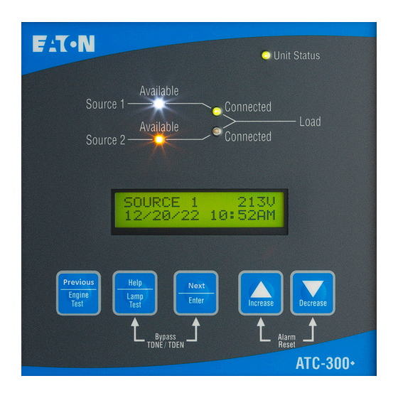
The automatic transfer controller LCD display will read 1. Help/lamp test “Lockout” if the source 2 circuit breaker is in the “tripped” posi- 2. Previous / engine test tion. 3. Next/enter 4. Increase 5. Decrease 6. Alarm reset 7. Bypass time delay (TDNE, TDEN) EATON www.eaton.com... - Page 7 1/20/06 3:35PM • Hardware revision number (= parts list revision number); See Section 3 for more detailed information. • Feature code – a decodable string listing all optional features programmed in the ATC-300+ Controller; and • Firmware version. EATON www.eaton.com...
- Page 8 The J4 and J8 connectors provide DC wetted connections for various control inputs. The J5 and J8 connectors provide dry relay contacts for primary control outputs. See Table 1 for contact ratings. EATON www.eaton.com...
- Page 9 Meets IEC 61000-4-2, 61000-4-3, 61000-4-4, 61000-4-5, 61000-4-6, and 61000-4-11 Meets CISPR 11, class A Complies with FCC part 15, class A Enclosure compatibility NEMA 1, NEMA 3R, NEMA 4/4X and NEMA 12 UV resistant ATC-300+ faceplate Input control contacts DC wetted (24 volts at 10 ma) EATON www.eaton.com...
-
Page 10: Status Monitoring And Setpoints
The day of the week can also be set with 1 = Sunday, 2 = Monday, etc. The time, date, and day of the week can be set in the program mode. Figure 3. The LCD display. EATON www.eaton.com... - Page 11 This counter will count up to 9999 hours and then turn over to 0000. It can be reset to zero with the front panel or via Modbus. EATON www.eaton.com...
-
Page 12: Typical Function Of The Atc-300+ Controller
A careful review of the remainder of this instruction booklet should address these special cases, but if questions remain additional information can be obtained from the web site and phone number on the last page of this booklet. EATON www.eaton.com... - Page 13 9 10 11 12 13 14 9 10 9 10 Output Relays Control Inputs 6.5 in. ote: The form C type contact (J5-11), was added 10/2019 ote: Emergency Inhibit will require a jumper if not used Figure 4. Connectors on the ATC-300+ Controller. EATON www.eaton.com...
-
Page 14: Operation
When the “Lockout” input is in the “Unconnected” state, the ATC-300+ Controller will not permit an automatic transfer operation. When the “Lockout” input is in the “Unconnected” state, the LCD display will be active continuously. It will read “Lockout” on line 2 EATON www.eaton.com... - Page 15 C contact of this relay is implemented with the common pin (J-5, pin 8), the normally closed pin (J-5, Pin 10), and normally open pin (J-5, pin 9). The alarm relay contacts are rated for 10 A, 1-3 HP @ 250 Vac. The DC rating is 10A @ 30 Vdc. EATON www.eaton.com...
- Page 16 Plant exercising in the load exercising mode is “Failsafe”. If the generator fails during testing for any reason, the ATC-300+ will signal the transfer switch to return to the source 1 power source. The ATC-300+ will display “FAILSAFE” until a pushbutton is pressed. EATON www.eaton.com...
-
Page 17: Programming
The user then steps through the setpoint screens and can change ATC-300+ display. the setpoint values. During this time, the unit status LED will blink at a faster rate. At the end of the setpoint screens, the user will be prompted to save the setpoints. EATON www.eaton.com... - Page 18 TPRE Minutes: seconds Pretransfer delay timer 0 sec to 120 sec 0:00 SWITCH TYPE Device types Breaker-, 3 position contactor-, 2 position contactor-, 3K-, MG As ordered PHASES Three phase or single phase 1 or 3 As ordered EATON www.eaton.com...
- Page 19 Resets LOAD ENERG counter 0 to 9999 XXXX LOAD ENERG RESET TRANSFERS Cycles (counts) Resets TRANSFERS counter 0 to 9999 XXXX * For a 3-phase delta source or HRG (high resistance grounding), this feature should be turned off. EATON www.eaton.com...
-
Page 20: Troubleshooting And Maintenance
For assistance with this determination, contact atstechsupport@eaton.com Eaton. If a problem is identified to be external to ATC-300, proceed to Section 7.3 and continue troubleshooting. If a message is flashing on top of the display and the cause of the fault is resolved, simply press increase-decrease buttons and the message will be removed. - Page 21 OCCURS, FIRST CONTACT THE LOCAL GENSET DEALER. IF THE RESULT IS NOT CORRECTED, CONTACT THE EATON ATS TECHNICAL SUPPORT AT 877-386-2273 ote: If a message is flashing on top of the display and the fault is removed, (877-ETN-CARE).
- Page 22 In all cases, the controller will remove the 120vac after 6 seconds. Vac (+/- 10 volts)? Record the reading. If yes: Proceed to step 6. Step 9. If a problem persists, contact Eaton. If no: Check voltage transformer NT1. Step 6. Is the power source available? For ATS assistance, call Eaton Care at: If yes: Proceed to step 8.
- Page 23 The printed circuit boards are calibrated and conformally coated at the factory. They are to be serviced by factory trained personnel only. The front panel including the display can be cleaned lightly with a soap and water mixture. EATON www.eaton.com...
-
Page 24: Appendix A. Display Message For Status
Waiting for the neutral position to be reached by the switch. WAITING FOR S1 TO CLOSE Waiting for the source 1 device (i.e. circuit breaker, contactor) to close. WAITING FOR S2 TO CLOSE Waiting for the source 2 device (i.e. circuit breaker, contactor) to close. EATON www.eaton.com... -
Page 25: Appendix B. Operational Flowcharts
Remove “Engine Start” signal (de-actuate gen start relay) Source 2 is powering the load Notes: 1- applicable for contactor type transfer switches with support for time delay in load disconnect (“neutral”) position 2- applicable for molded case type transfer switches EATON www.eaton.com... - Page 26 TDEC time delay expires load disconnect) Close Source 2 main contacts Remove “Engine Start” signal (actuate K4 relay) (de-actuate gen start relay) Notes: 1- applicable for contactor type transfer switches with support for time delay in load disconnect (“neutral”) position EATON www.eaton.com...
- Page 27 Automatic Transfer Switch Controller, ATC-300+ Instruction Booklet IB01602009EN operation and maintenance manual Effective April 2024 Notes: EATON www.eaton.com...
- Page 28 USAGE OF TRADE, ARE MADE REGARDING THE INFORMATION, RECOMMENDATIONS AND DESCRIPTIONS CONTAINED HEREIN. In no event will EATON be responsible to the purchaser or user in contract, in tort (including negligence), strict liability or otherwise for any special, indirect, incidental or consequential damage or...
Need help?
Do you have a question about the ATC-300+ and is the answer not in the manual?
Questions and answers