
Related Manuals for McCrometer SPI Mag 3000


Summary of Contents for McCrometer SPI Mag 3000
- Page 1 SPI M SPI Mag 3000 Single Point Insertion Electromagnetic Flow Meter 1” and 2” Sensors Installation, Operation and Maintenance Manual 30126-41 Rev. 1.0 26AUG2024...
-
Page 2: Table Of Contents
Contents SAFETY SYMBOLS AND WARNINGS ........... . 1 Safety Symbols . -
Page 3: Safety Symbols And Warnings
Safety Warnings When installing, operating, and maintaining McCrometer equipment where hazards may be present, you must protect yourself by wearing Personal Protective Equipment (PPE) and be trained to enter confined spaces. Examples of confined spaces are manholes, pumping stations, pipelines, pits, septic tanks, sewage digesters, vaults, degreasers, storage tanks, boilers, and furnaces. -
Page 4: Spi Mag Description Of Components
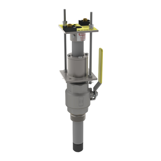
SPI M SPI Mag Description of Components SPI MAG DESCRIPTION OF COMPONENTS Overview The SPI Mag Model 282L flowmeter combines an innovative sensor with a comprehensive electronics package to provide accurate flow measurement for full-pipe flow monitoring applications. The insertable sensor (available for one-inch and two inch taps) uses electromagnetic technology to measure water velocity. The streamlined, debris-shedding sensor shape allows the SPI Mag to be used under many flow conditions. -
Page 5: Flow Calculation
SPI M SPI Mag Description of Components Flow Calculation The velocity measurements provided by the full-pipe sensor are used to calculate flow. Flow (also known as Q, as the flow rate, or as throughput) is the amount of fluid moving through a pipe in a period of time. For example, if 100 gallons of water move past the sensor in one minute, the flow is 100 gallons per minute (GPM). -
Page 6: Parts Diagrams
SPI M Parts Diagrams PARTS DIAGRAMS 282L 1” Sensor 282L 2” Sensor Figure 4. Parts Diagrams Item Number Part Name and Part Number Sensor Assembly 1" 60080X001 Sensor Assembly 2" 600028X001 Ball Valve 1” Bronze 43801 Ball Valve 2” Bronze 43055 Compression Seal Assembly 1"... -
Page 7: Sensor Probe Installation
SPI M Sensor Probe Installation SENSOR PROBE INSTALLATION Please read the following information before installing the SPI Mag Sensor Site Selection Install the sensor at an adequate distance from elbows, T-junctions, Y-junctions, active valves. Whenever possible, install the sensor upstream from a bend or junction. Sensor Clearance The sensor will protrude from the pipe when installed demanding sufficient clearance (distance H, in Figure 5 below) from any obstruction for the purposes of installation and removal. -
Page 8: Pipe Valve Installation
SPI M Sensor Probe Installation Pipe Valve Installation WARNING! Pressurized pipes should only be hot tapped, cut, or drilled by qualified personnel using high quality saddles, valves ad stainless steel nipples. If possible, depressurize the pipe before attempting any installation. Install a 2”... -
Page 9: Inserting The Sensor
SPI M Sensor Probe Installation Inserting The Sensor WARNING! The compression seal/sensor assembly may be under pressure. Serious injury may result if proper procedures are not followed. Do not attempt to install the sensor without the restraining rods fully assembled. Ensure the compression seal is only hand tightened. -
Page 10: Raw Water Sensor Position
Sensor Insertion Tool High Gear Shaft McCrometer recommends using a sensor insertion tool (Figure 12) (P/N 75031) to help with inserting the sensor and to avoid any damage to the sensor. Place the profiling insertion tool over the captive nuts and lock it into place with spring locks located on the bottom of the tool. -
Page 11: Sensor Removal
SPI M Sensor Removal SENSOR REMOVAL WARNING! The pipe may be under pressure. Serious injury or death may result if proper procedures are not followed. To remove the sensor follow the steps below: Visually inspect the pipe and entire assembly for damage or corrosion paying close attention to any nipples and welded couplings. -
Page 12: Flow Meter Specifications
• PVC Insertion Tube: Up to 105°F (41°C) at 150 PSI temperature limits • Stainless Steel Insertion Tube: Up to 160°F (71°C) at 250 PSI (McCrometer recommends the use of Stainless Steel) Note regarding storage: During freezing conditions and when meter is not in use, sensor must be removed from pipe and stored in dry conditions. - Page 13 Speci cation Sheet SPI M Specifications SPI M SPI Mag Series Flow Meter Flow Meter Speci cations (cont.) System Options • Stainless Steel ID Tag • Sensor Insertion Tool • Additional Sensor Cable up to 200’ (for longer lengths consult factory) •...
- Page 14 SPI M Specifications SPECIFICATIONS ProComm 3000 PROCOMM GO CONVERTER SPECIFICATIONS 10.0 SPECIFICATIONS Physical Speci cations Electronic Housing Diecast aluminum, powder coated enclosure w/ tamper resistant seal, 6½” x 6½” x 43/8” tall Transmitter See "Dimensions" section for meter mount and remote mount transmitter dimensions. Dimensions Battery: Standard: three 3.6V lithium-thionyl chloride (Li-SOCI2) D size...
-
Page 15: Certi Cations
SPI M Specifications SPECIFICATIONS ProComm 3000 PROCOMM GO CONVERTER SPECIFICATIONS (CONT.) Display and Measurement (cont.) Gallons Barrel (42G) Miners Inch Hour (11.22G) Cubic Feet Barrel (46G) Miners Inch Day (11.22G) Acre Feet Barrel (55G) Miners Inch Hour (9G) CUM Cubic Meters Imperial Gallon Miners Inch Day (9G) Totalizer Units... -
Page 16: Spi Mag Ordering Information
Prior to calling for a return authorization number, determine the model number, serial number (located inside the front panel of converter), and reason for return. • Contact McCrometer Customer Service Department and ask for a Return Authorization (RA) number. • Telephone: 1-800-220-2279 •... -
Page 17: Conversion Tables
SPI M Conversion Tables CONVERSION TABLES Table of Decimal Equivalents Fraction Decimal .125 .375 .625 .875 Table of Conversions Multiply To Get Centimeters 0.3937 Inches Centimeters 0.03281 Feet Inches 25.4 Millimeters Feet 30.48 Centimeters Square Feet 144.0 Square Inches Square Inches 0.006944 Square Feet Cubic Inches... -
Page 18: Warranty Statement
AGENTS PURSUANT TO ANY QUOTATION. Copyright © 2024 McCrometer, Inc. All printed material should not be changed or altered without permission of McCrometer. Any published pricing, technical data, and instructions are subject to change without notice. Contact your McCrometer representative for current pricing, technical data, and instructions.
Need help?
Do you have a question about the SPI Mag 3000 and is the answer not in the manual?
Questions and answers