Subscribe to Our Youtube Channel
Summary of Contents for McCrometer SmartTrax
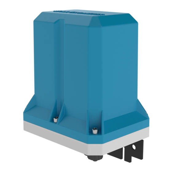
- Page 1 SmartTrax Remote Telemetry Unit for Propeller and Electromagnetic Flow Meters Installation, Operation and Maintenance Manual 30125-82 March 28, 2023...
-
Page 2: Table Of Contents
OVERVIEW OF THE SMARTTRAX REMOTE TELEMETRY UNIT . . . . . . . . . . . . . . . . . -
Page 3: Safety
The National Electrical Code (NEC) provides measures that, when fully complied with, ensure electrical safety of the device. The SmartTrax device must be grounded in a manner in compliance with the NEC (or other observed regulatory standard) in order to ensure this level of safety to personnel that come in contact with this device. -
Page 4: Overview Of The Smarttrax Remote Telemetry Unit
The RTU can also supply 5V to power certain sensors. This RTU is compatible with all McCrometer flowmeters configured with AMI or pulse output, but it is designed to be used with any signal converter with AMI or pulse output also. -
Page 5: Verifying The Unit Serial Number
This manual contain instructions both new installation and after-market installation of the SmartTrax. Because there are several different possible flow meter configurations, each retrofit has its own stand-alone set of instructions. See Figure 5. -
Page 6: Mounting The Smarttrax
INSTALLING THE SMARTTRAX 3 .2 Mounting the SmartTrax If the mounting bracket is not attached, attach it to to bottom of the unit as shown in Figure 6. Surface mount: Mount the unit to a solid flat surface with two wood screws. (Figure 7) Pole mount: Mount the unit to a pole using two metal clamps. -
Page 7: Pin-Out Of Male And Female Connectors
5.1W respectively (Figure 4). Do not use the optional the solar panel used to provide power to the ProComm GO converter. Install the solar panel adjacent to and below the SmartTrax unit so that the two can be connected with the 6’ cable. Do not allow the solar panel to overshadow the unit’s antenna, which is... -
Page 8: Battery Installation
BATTERY INSTALLATION 4 .0 BATTERY INSTALLATION SmartTrax Battery Connection and Installation Instruction Start-up Procedure and Battery Installation Materials Provided (shown in order of use) and Replacement Procedure for the SmartTrax One triple D battery pack Telemetry Unit Optional rechargeable battery pack... - Page 9 BATTERY INSTALLATION SmartTrax Battery Connection and Installation Instruction Release the wires from the wire guides. Remove the primary battery. Follow steps 7 and/or 8 according to your transmitter’s con guration and which battery you need to replace. Remove the secondary battery.
- Page 10 14. Replace cover securely and tighten the screws. Copyright © 2023 McCrometer, Inc. All printed material should not be changed or altered without permission of McCrometer. Any published pricing, technical data, and instructions are subject to change without notice. Contact your McCrometer representative for current pricing, technical data, and instructions.
-
Page 11: Operation
“Send Verification Code”. account. While you’re creating your account, you’ll get an email from Microsoft on behalf of McCrometer. Open the email and find the verification code. To finish creating your Enter “New Password”, Re- STEP 2: Log-in to your account account, enter the enter password, “Confirm New... - Page 12 OPERATION STEP 3: Add SMARTTRAX Unit Click on “Add Device”. Enter “SIM Id”, “IMEI” and “Device Serial Number” provided with device. If information is lost, please contact customer service. Click on “ADD DEVICE” Click on “TAKE OWNERSHIP” if you will be responsible for reoccurring data fees.
- Page 13 OPERATION Make changes to Configuration as needed and click on “DONE” to return to Dashboard. Unit has been added to your Account successfully. Page 11 30125-82 Rev. 1.0 | 28MAR2023...
-
Page 14: Specifications
Pulse Inputs: SmartTrax can receive two pulse inputs (forward and reverse total)from any open collector pulse output device. AMI Input: SmartTrax can receive a digital total from any AMI compatible device output. AMI Input with ProComm Go Converter: SmartTrax can receive Rate, Total(s), meter and diagnostic information using McCrometer’s proprietary communication. - Page 15 Specifications Accessories Serial Accessories USB cable: EA200-USB Power Accessories Solar Panels: Solar Cable: 2.4W: 200.723.520 TEL-CBL-006-5F 5.1W: 200.733.522 Sensor Accessories Input Cables: Power/ Output Cables: 6 ft: TEL-CBL-F-006-OE 25 ft: TEL-CBL-M-025-OE 25 ft: TEL-CBL-F-025-OE 50 ft: TEL-CBL-M-050-OE 50 ft: TEL-CBL-F-050-OE Page 13 30125-82 Rev.
-
Page 16: Dimensions
Prior to calling for a return authorization number, determine the model number, serial number (located inside the front panel of the converter), and reason for return. • Contact McCrometer Customer Service Department and ask for a Return Authorization (RA) number. • Telephone: 1-800-220-2279 •... -
Page 17: Warranty
Computing devices sold but not manufactured by McCrometer, Inc. are covered only by the original manufacturer’s written warranty. Hence, this warranty statement does not apply. - Page 18 ™ Copyright © 2022 McCrometer, Inc. All printed material should not be changed or altered without permission of McCrometer. Any published pricing, technical data, and instructions are subject to change without notice. Contact your McCrometer representative for current pricing, technical data, and instructions.


Need help?
Do you have a question about the SmartTrax and is the answer not in the manual?
Questions and answers