
Related Manuals for Precor GluteBuilder GPL724/D45HE


Summary of Contents for Precor GluteBuilder GPL724/D45HE
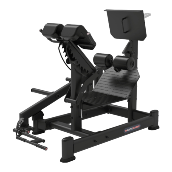
- Page 1 GPL724/D45HE DUAL 45 HIP EXTENSION OWNER'S MANUAL CAUTION! Read all precautions and instructions in this manual before using this equipment. GPL724SMS01...
-
Page 2: Table Of Contents
Table Of Contents CAUTION! Read all precautions and instructions in this manual before using this equipment. Important Safety Instructions----------------------------------------------------------- 3 Instructions-------------------------------------------------------------------------------- 5 Exploded View and Parts List------------------------------------------------------------ 6 Measurement Guide--------------------------------------------------------------------- 18 Assembly Instructions------------------------------------------------------------------ 19 Assembly--------------------------------------------------------------------------------- 20 Adjust Instructions and Exercise Instructions---------------------------------------- 27 Maintenance Schedule------------------------------------------------------------------ 28 General Maintenance Information----------------------------------------------------- 29 Weight Training Tips-------------------------------------------------------------------- 30... -
Page 3: Important Safety Instructions
Important Safety Instructions Before beginning any fitness program, you should obtain a complete physical examination from your physician. When using exercise equipment, basic precautions should always be taken, including the following: 1. Read all instructions before using the equipment. These instructions are written to ensure your safety and to protect the unit. 2. - Page 4 Important Safety Instructions Personal Safety During Assembly Read each step in the assembly instructions and follow the steps in sequence. Do not skip ahead. If you skip ahead, you may learn later that you have to disassemble components and that you may have damaged the equipment. Assemble and operate the equipment on a solid, level surface.
-
Page 5: Instructions
Instructions Before beginning assembly please take the time to read instructions thoroughly. Please use the various lists in this manual to make sure that all parts have been included in your shipment. When ordering, use part number and description from the lists. -
Page 6: Exploded View And Parts List
Exploded View and Parts List Overall Item No. Part No. Description D45HEGB01ASSY / D45HE01ASSY Rear Main Frame ASSY D45HE02ASSY Ground Frame ASSY D45HE03ASSY Bearing Frame ASSY D45HE04ASSY Front Main Frame ASSY D45HE06ASSY Swing Frame ASSY D45HE08ASSY Upper Handlebar ASSY D45HE05ASSY Pedal Frame ASSY D45HE09ASSY FOAM Frame ASSY... - Page 7 Exploded View and Parts List Overall Item No. Part No. Description BB-PL5000V1 Aluminium Cap Φ49*Φ12.5*10 PKB2000 Aluminium Cap Φ63*Φ12.5*10.5 GB70M8*30*30DY20 Socket Head Cap ScrewM8*30 GB70M10*25DY20NL Socket Head Cap ScrewM10*25 GB70M10*25DY20 Socket Head Cap ScrewM10*25 GB70M12*75DY20 Socket Head Cap ScrewM12*75 GB70M10*60DY20 Socket Head Cap ScrewM10*60 GB70M12*85DY20 Socket Head Cap ScrewM12*85...
- Page 8 Exploded View and Parts List Overall...
- Page 9 Exploded View and Parts List Rear Main Frame ASSY (fit for D45HE) Item No. Part No. Description D45HE0100 Rear main frame KGI19ASSY PIN ASSY PKB3100 Large Elliptical Pipe Plug R60*120 PKB3200 Floor Mat IT95014300V2 Sliding sleeve IT95016200 Open oval plug IT95016300 Slider GB956DY2...
- Page 10 Exploded View and Parts List Rear Main Frame ASSY (fit for GPL724) Item No. Part No. Description D45HE0100 Rear main frame KGI19ASSY PIN ASSY PKB3100 Large Elliptical Pipe Plug R60*120 PKB3200 Floor Mat IT95014300V2 Sliding sleeve IT95016200 Open oval plug IT95016300 Slider GB956DY2...
- Page 11 Exploded View and Parts List Ground Frame ASSY Bearing Frame ASSY Item No. Part No. Description D45HE0200 Ground Frame PKB3100 Large Elliptical Pipe Plug R60*120 PKB3200 Floor Mat YZGB290.25*20*18DS20 Hex Head Cap Screw 1/4*20 Item No. Part No. Description D45HE0300 Bearing frame PKB1300 Short Elastic Band Holder...
- Page 12 Exploded View and Parts List Front Main Frame ASSY Swing Frame ASSY Item No. Part No. Description D45HE0400 Front main frame M02502000 Bushing Φ25.4 Item No. Part No. Description D45HE0600 Swing frame PKB1300 Short Elastic Band Holder D45HE2800 Lining Board PKB3300 Large Elliptical Pipe Plug R50*100 BB-PL5000V1...
- Page 13 Exploded View and Parts List Pedal frame ASSY Upper Handlebar ASSY Item No. Part No. Description D45HE0800 Upper Handlebar M02502000 Bushing Φ25.4 V39600V2 Aluminium Grip Cap Φ25.4 V39500V2 Aluminium Grip Ring Φ25.4 SD1004B1600 Grip YZGB7710-32*3.2DY2 Socket Set Screw 10-32*3.2 Item No. Part No. Description D45HE0500 Pedal frame...
- Page 14 Exploded View and Parts List FOAM Frame ASSY Adjusting Frame ASSY FOAM ASSY Item No. Part No. Description D45HE0900 FOAM Frame IF81165000 Lock Nut M10 Item No. Part No. Description D45HE1000 Adjustment pipe IN-D10134200 Plug J30*70 GB17880.5M10*19.5DS17 Rivet nut M10 Item No.
- Page 15 Exploded View and Parts List Rear Pedal Frame ASSY Item No. Part No. Description 10.1 D45HE1200 Rear pedal Frame 10.2 D45HE2700 Rear anti-skid plate 10.3 D45HE3200 Rubber pad 10.4 CF2165A2400 Grip 10.5 IN-D10134200 Plug J30*70 10.6 V39600V2 Aluminium Grip Cap Φ25.4 10.7 V39500V2 Aluminium Grip Ring Φ25.4...
- Page 16 Exploded View and Parts List Barbell Frame ASSY Pull Handle ASSY Item No. Part No. Description 12.1 D45HE1400 Barbell Frame 12.2 BB-PL5000V1 Aluminium Cap Φ49*Φ12.5*10 12.3 PNLM12*25DY20NL Button Head Cap Screw M12*25 12.4 HZ70022000 Short Barbell Casing 12.5 PL1301600 Buffer Pad Φ76*26 Item No.
- Page 17 Exploded View and Parts List Handle Turning Handlebar Frame ASSY Frame ASSY Item No. Part No. Description 13.1.1 D45HE0700 Handle Turning Frame 13.1.2 D45HE18ASSY PIN ASSY 13.1.3 FS521900 Copper Bushing Item No. Part No. Description 13.2.1 D45HE1100 Handlebar Frame 13.2.2 CWRVL0231900 Grip 13.2.3...
-
Page 18: Measurement Guide
Measurement Guide BHCS = Button Head Cap Screw SHCS = Socket Head Cap Screw FHCS = Flat Head Cap Screw HHB = Hex Head Bolt CRPHS = Cross Recessed Pan Head Screw Millimeters Inches Diameter of bolt M6(1/4") M8(5/16") M10(3/8") M12(1/2") M16(5/8") (mm/inch) -
Page 19: Assembly Instructions
Assembly Instructions Assembly of the equipment takes professional installers about 2 hours. If this is the first time you have assembled this type of equipment, plan to spend more time. It is strongly recommended to assemble the equipment by professional installers. You may find it quicker, safer, easier to assemble this equipment with the help of a friend, as some of components may be large, heavy or awkward to handle alone. -
Page 20: Assembly
Assembly STEP 1 Attach one Ground Frame ASSY (#2) to Rear Main Frame ASSY (#1), using: two M12*85 SHCS (#32) two Φ13*Φ26*2 Flat Washer (#41) two Φ12 Spring Washer (#42) Note: No Need To Tighten Bolts. - Page 21 Assembly STEP 2 1. Attach one Pedal Frame ASSY (#7) to Rear Main Frame ASSY (#1), using: four M12*145 SHCS (#32) four M12 Nylon Lock Nut (#39) eight Φ13*Φ26*2 Flat Washer (#41) 2. Attach one Front Main Frame ASSY (#4) to Pedal Frame ASSY (#7) and Front Ground Frame ASSY (#1), using: two M12*85 SHCS (#31) one M12*145 SHCS (#32)
- Page 22 Assembly STEP 3 1. Attach one Link Span (#11) to Pedal Frame ASSY (#7), using: two M12*75 SHCS (#29) two M12 Nylon Lock Nut (#39) four Φ13*Φ26*2 Flat Washer (#41) 2. Attach one Bearing Frame ASSY (#3) to Rear Main Frame ASSY (#1), Link Span (#11), Front Main Frame ASSY (#4), using: six M12*85 SHCS (#31) four M12 Nylon Lock Nut (#39)
- Page 23 Assembly STEP 4 1. Attach one Swing Frame ASSY (#5) to Bearing Frame ASSY (#3), using: one Shafe (#17) two Cap Φ63 (#25) two M12*25 BHCS (#36) 2. Attach one Pull Handle ASSY (#13) to Swing Frame ASSY (#5), using: two Cap Φ43 (#25) two M10*25 FHCS (#34) 3.
- Page 24 Assembly STEP 5 1. Attach one Upper Handlebar ASSY (#6) to Front Main Frame ASSY (#4), using: two Pulley (#22) two Φ11*Φ23*2 Flat Washer (#40) two M10*25 BHCS (#35) Note that the Pulley (#22) can only be assembled through hole No. 9 of the Upper Handlebar ASSY (#6).
- Page 25 Assembly STEP 6 1. Attach one FOAM Frame ASSY (#8) to Adjusting Frame ASSY (#9), using: one M10*25 SHCS (#27) one M10*60 SHCS (#30) three Φ11*Φ23*2 Flat Washer (#40) one M10 Nylon Lock Nut (#38) 2. Attach one Adjusting Frame ASSY (#9) to Rear Main Frame ASSY (#1), using: one M8*30 SHCS (#26) 3.
- Page 26 Assembly STEP 7 1. Attach two Leg Pad (#21) to Upper Handlebar ASSY (#6), using: eight M10*25 SHCS (#28) eight Φ11*Φ23*2 Flat Washer (#40) 2. Attach two FOAM ASSY (#20) to FOAM Frame ASSY (#8), using: two Cap Φ63 (#25) two M10*25 BHCS (#35) 3.
-
Page 27: Adjust Instructions And Exercise Instructions
Adjust Instructions and Exercise Instructions Desired position adjustment 1. Pull the spring pin, adjust the Pull Handle Frame, FOAM Frame, Rear pedal Frame to the desired position and then release the spring pin. 2. Make sure the pin gets into the hole completely. -
Page 28: Maintenance Schedule
Maintenance Schedule COMMERCIAL HOME LATEST DATE ENTRY ROUTINE MAINTENANCE MAINTENANCE Inspect; Links, Pull Pins, Snap Locks, DAILY WEEKLY Swivels, Weight Stack Pins Clean; DAILY WEEKLY Upholstery Inspect; DAILY WEEKLY Cables or Belts and their tension Inspect; WEEKLY 3 MONTHS Accessory Bars, and Handles Inspect;... -
Page 29: General Maintenance Information
General Maintenance Information Links, Pull-Pins, Snap Hooks, Swivels, Weight Stack Pins: * Check all pieces for signs of visible wear or damage. * Check springs in snap hooks and pull-pins for proper tension and alignment. * If the spring sticks or has lost its rigidity, replace it immediately. Upholstery: * To ensure prolonged upholstery life and proper hygiene, all upholstered pads should be wiped down with a damp cloth after every workout. -
Page 30: Weight Training Tips
Weight Training Tips Use this manual to guide you through the basic exercises you can perform on your equipment. To gain maximum results and avoid possible injury, consult a fitness professional to develop your complete exercise program. Always consult your physician before starting any exercise program. To be successful in your exercise program, it is important to develop an understanding of the basic principles of strength training.
Need help?
Do you have a question about the GluteBuilder GPL724/D45HE and is the answer not in the manual?
Questions and answers