Table of Contents
Advertisement
Quick Links
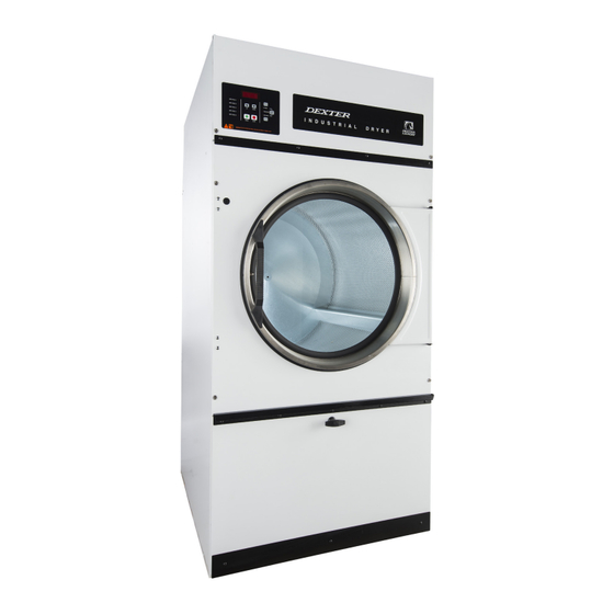
DCBD( 30/ 50/ 80) HC-10/ 39 Series Dryers
For
The dryer must not be stored or installed w here it w ill be exposed to w ater and/ or w eather.
WARNI NG: For your safety the infor-
mation in this manual must be fol-
lowed to minimize the risk of fire or
explosion or to prevent property dam-
age, personal injury or loss of life.
-Do not store or use gasoline or other
flammable vapors and liquids in the vicinity of
this or any other appliance.
– WHAT TO DO I F YOU SMELL GAS
• Do not try to light any appliance.
• Do not touch any electrical switch; do not
use any phone in your building.
• Clear the room, building or area of all
occupants.
• I mmediately call your gas supplier from a
neighbor's phone. Follow the gas supplier's
instructions.
• I f you cannot reach your gas supplier, call
the fire department.
– I nstallation and service must be performed by
a qualified installer, service agency or the gas
supplier.
Post the following "For Your Safety" caution in a
prominent location:
FOR YOUR SAFETY
Do not store or use gasoline or other flammable
vapors or liquids in the vicinity of this or any
other appliance.
I t is important that you read this Manual and retain it
for future reference. For service or replacement parts,
contact the distributor in your area or the manufacturer.
OPERATOR'S MANUAL
Dexter Laundry I nc.
2211 West Grimes Avenue
Fairfield, I owa 52556
AVERTI SSEMENT.
de
bien suivre les instructions
données dans cette notice pour
réduire au minimum le risque
d'incendie ou d'explosion ou pour
éviter tout
dommage matérial,
toute blessure ou la mort.
Ne pas entreposer ni utiliser d'essence ni d'autres
vapeurs ou
liquides inflammables dans le
voisinage de cet appareil ou de tout autre
appareil.
– QUE FAIRE SI VOUS SENTEZ UNE ODEUR DE GAZ:
• Ne pas tenter d'allumer d'appareil.
• Ne touchez à aucun interrupteur. Ne pas
vous servir des téléphones se trouvant
dans le bâtiment où vous trouvez.
• Évacuez la pièce, le bâtiment ou la zone.
• Appelez immédiatement votre fournisseur
de gaz depuis un voisin. Suivez les
instructions du fournisseur.
• Si vous ne pouvez rejoindre le fournisseur
de gaz, appelez le service des incendies.
– L'installation et l'entretien doivent être assures
par un installateur ou un service d'entretien
qualifie ou par le fournisseur de gaz.
POUR VOTRE SÉCURI TÉ
Ne pas ente poser ni utiliser d'essence ni d'autres
vapeurs ou liquides inflammables dans le voisinage
de cet appareil ou de tout autre appareil.
You, the purchaser, must post in a prominent loca-
tion instructions to be followed in the event the user
smells gas. Consult your local gas supplier for pro-
cedure to be followed if the odor of gas is present.
8514-209-001A
May 2012
Assurez-vouz
Advertisement
Table of Contents

Related Manuals for Dexter Laundry DCBD HC-10 Series


Summary of Contents for Dexter Laundry DCBD HC-10 Series
- Page 1 Consult your local gas supplier for pro- cedure to be followed if the odor of gas is present. Dexter Laundry I nc. 2211 West Grimes Avenue Fairfield, I owa 52556...
-
Page 2: Table Of Contents
TABLE OF CONTENTS DRYER DI MENSI ONS (Figure 1)........…........3 DRYER CAPACI TI ES..............…....UNCRATI NG ...…..............…....6 DRYER I NSTALLATI ON ................... 6 DRYER EXHAUST SYSTEM (Figure 2) ............... 10 DRYER SHUTDOWN ..................10 DRYER CONTROLLER I NTERFACE (Figure 3) …………………………………………………. 11 DRYER CONTROLLER FACTORY DEFAULT PROGRAM SETTI NG ...... -
Page 3: Dryer Di Mensi Ons (Figure 1)
DRYER DI MENSI ONS- FI GURE 1A - 3 -... - Page 4 DRYER DI MENSI ONS- FI GURE 1B - 4 -...
- Page 5 DRYER DI MENSI ONS- FI GURE 1C - 5 -...
-
Page 6: Dryer Capaci Ti Es
DRYER CAPACI TI ES Dryer Model Dry Weight Capacity DCBD30 30 lb (13.6 kg) DCBD50 50 lb (22.7 kg) DCBD80 80 lb (36.3 kg) I NSTALLATI ON AND OPERATI NG I NSTRUCTI ONS I NDUSTRI AL DRYER UNCRATI NG Tools required: 3/ 4” hex socket and ratchet driver, knife, channel-lock wrench that opens to 1 3/ 8". 1. -
Page 7: Electrical Requirements
Refer to installation label attached to the inside surface of the upper door of the dryer for other installation information. VERTI CAL CLEARANCE DI MENSI ONS - ALL DCBD( 30/ 50/ 80) 3. MAKE- UP AI R . Adequate make-up air must be supplied to replace air exhausted by dryers on all types of installations. -
Page 8: I Mportant: Transi Ent Voltage Surge Suppressors
I ndividual circuit breakers for each unit are recommended. The wiring diagram is located on the belt guard on the back of the machine. I MPORTANT: TRANSI ENT VOLTAGE SURGE SUPPRESSORS Like most electrical equipment, your new machine can be damaged or have its life shortened by voltage surges due to lightening strikes which are not covered by factory warranty. - Page 9 This pipe must be very smooth on the inside, as rough surfaces tend to collect lint which will eventually clog the duct and prevent the dryer from exhausting properly. All elbows must be smooth on the inside. All joints must be made so the exhaust end of one pipe is inside the next one downstream.
-
Page 10: Dryer Exhaust System (Figure 2)
7. DRYER I GNI TI ON ( SOLI D STATE I GNI TI ON) . The solid state ignition system lights the main burner gas by spark. The gas is ignited and burns only when the gas-valve relay (in the electronic controller) calls for heat. -
Page 11: Dryer Controller I Nterface (Figure 3)
Figure 3 – Non- Reversing Dryer Controller I nterface. - 11 -... -
Page 12: Dryer Controller Factory Default Program Setti Ng
DRYER CONTROLLER FACTORY DEFAULT PROGRAM SETTI NGS DRYI NG COOL TOTAL TEMPERATURE DOWN TI ME CYCLE TI ME DRYER LOAD CYCLE (minutes) (minutes) (º F) (º C) Towels, pads, heavy cotton Sheets, blended materials Cotton Synthetic Materials Blended Materials DRYER FAULT CODES FAULT FAULT # ACTI ON... -
Page 13: Touch Pad Descri Pti On
TOUCH PAD DESCRI PTI ON INDICATOR LIGHTS (L.E.D.s) Description Cycle ( 1 through 5) These L.E.D.s are on solid when a particular cycle is chosen for operation or programming. Gas Valve This L.E.D. is part of the 4-digit numeric display and will be on solid during the drying part of a cycle when the gas valve does not need to be on. - Page 14 4- DI GI T NUMERI CAL DI SPLAY MESSAGES Description LOAd This message is displayed after a dry cycle is complete and the dryer loading door has been opened or the STOP touch pad switch on the dryer controller has been pressed and released twice.
-
Page 15: Operati Ng I Nstructi Ons
OPERATI NG I NSTRUCTI ONS To dry a load of items, you must choose one of the five-programmed dry cycles. Each of these five dry cycles may be modified in two different ways to match your load. Please, refer to the “Permanent Dryer Controller Programming”... -
Page 16: Temporary Dryer Controller Programmi Ng
The bottom and middle pins are for Celsius and the top and middle pins are for Fahrenheit, which is indicated by the letter C for Celsius and the letter F for Fahrenheit. The other jumper, located at the upper right side of the component side of the dryer controller circuit board, is used for choosing either a reversing or non-reversing type of dryer. - Page 17 5) Press and release the SELECT/ ENTER touch pad switch on the dryer controller. Once the SELECT/ ENTER touch pad switch is pressed and released, the dry time L.E.D. will switch off, the dry cycle L.E.D. and programming L.E.D. will remain on, the temperature L.E.D. will illuminate, and the drying temperature will be shown on the 4-digit numeric display.
-
Page 18: Permanent Dryer Controller Programmi Ng
3) Press and release the touch pad switch on the dryer controller 10 times so that the display will show a flashing “ 45”. When the touch pad switch is pressed the first time, the number “36” will be flashing on the dryer controller display. - Page 19 cycle L.E.D. and the programming L.E.D. will remain illuminated, and the total dry time will also be displayed on the 4-digit numeric display. 6) Press and release either the DOWN touch pad switch on the dryer controller to change the total dry DOWN time.
- Page 20 PROCEDURE: DOWN 1) After the load has been placed in the dryer, press and release either the touch pad switch on the dryer controller until the L.E.D. for dry cycle 1 is illuminated. PROG 2) Press and release the touch pad switch on the dryer controller. The display of the dryer controller will not change.
-
Page 21: Servi Ci Ng And Troubleshooti Ng Dryer
SERVI CI NG THE DRYER CAUTI ON : Label all wires prior to disconnection when servicing controls. Wiring errors can cause improper and dangerous operation. Verify proper operation after servicing. ATTENTI ON : Au moment de l'entretien des commandes, étiquetez tous les fils avant de les débrancher. Des î... -
Page 22: Preventi Ve Mai Ntenance I Nstructi Ons
9822-026-001 9822-031-002 For service and parts information, contact your local Dexter agent. To find your local Dexter agent, use the Dexter Laundry, Distributor Locator at the website shown below. I f a Dexter agent is not available, contact I nc.
Need help?
Do you have a question about the DCBD HC-10 Series and is the answer not in the manual?
Questions and answers