Advertisement
Quick Links
Advertisement

Related Manuals for Ofs Ramble Table


Summary of Contents for Ofs Ramble Table
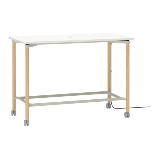
- Page 1 Ramble assembly...
-
Page 2: Important Safety Instructions
A double-insulated product is marked with the words “DOUBLE INSU- LATION” OR “DOUBLE INSULATED”. The symbol (square within a square) is also able to be marked on the product. Save these instructions ofs.com imagine a place® 800.521.5381 Assembly instructions... - Page 3 Table of Contents Important safety instructions Table of contents Table frame assembly Attaching the top to frame assembly 9-12 Lower rail assembly for counter and bar height 13-15 Installing power units Engaging ganging bracket ofs.com imagine a place® 800.521.5381 Assembly instructions...
- Page 4 Repeat for both sides of the support rail View 1-1 VIEW 1-1 VIEW 1-1 #10-24 x .50" button head screw Dwg #: Desc: Eng: Date: View 1-2 VIEW 1-2 Desc: Eng: Date: Tolerance: ± .03125"; Angular: ± .5° Unless Noted ofs.com imagine a place® 800.521.5381 Assembly instructions...
- Page 5 Repeat for both sides of the support rail VIEW 2-2 View 2-1 VIEW 2-1 Dwg #: Desc: Eng: Date: Tolerance: ± .03125"; Angular: ± .5° Unless Noted #10-24 x .50" View 2-2 VIEW 2-2 ofs.com imagine a place® 800.521.5381 Assembly instructions...
- Page 6 ALIGN ALL 4 CORNERS VIEW 3-2 Dwg #: Desc: Eng: Date: Tolerance: ± .03125"; Angular: ± .5° Unless Note View 3-2 VIEW 3-2 Eng: Date: Tolerance: ± .03125"; Angular: ± .5° Unless Noted ofs.com imagine a place® 800.521.5381 Assembly instructions...
- Page 7 Each leg receives 5 screws as shown in view 4-2 VIEW 4-2 #12 x 1" flat head screws View 4-1 VIEW 4-1 Dwg #: Desc: Eng: Date: Tolerance: ± .03125"; Angular: ± .5° Unless Noted View 4-2 VIEW 4-2 ofs.com imagine a place® 800.521.5381 Assembly instructions...
- Page 8 NOTE: the # of screws on the step will vary base on table size #8 x 3/4" pan screw View 5-1 VIEW 5-1 Dwg #: Desc: Eng: Date: Tolerance: ± .03125"; Angular: ± .5° ofs.com imagine a place® 800.521.5381 Assembly instructions...
- Page 9 Repeat for both sides of the foot rail Shorter foot rail View 1-1 VIEW 1-1 VIEW 1-1 1/4"-20 x 5/8" flat head screws View 1-2 VIEW 1-2 ofs.com imagine a place® 800.521.5381 Assembly instructions VIEW 1-2 Desc: Eng: Date: Tolerance: ± .03125"; Angular: ± .5° Unless Noted...
- Page 10 Install the foot rail assembly from the previous step to the longer foot rail as shown in view 2-1 NOTE: The orientation of the countersunk hole Longer foot rail View 2-1 VIEW 2-1 Dwg #: Desc: Eng: Date: Tolerance: ± .03125"; Angular: ± .5° Unless No ofs.com imagine a place® 800.521.5381 Assembly instructions...
- Page 11 Attach the foot rail assembly using 2x 1/4-20 x 5/8" flat head screws and 5/ 3 2" Allen wrench as shown in view 3-1 Repeat for both sides of foot rail 1/4"-20 x 5/8" flat head screws View 3-1 VIEW 3-1 Dwg #: Desc: Eng: Date: Tolerance: ± .03125"; Angular ofs.com imagine a place® 800.521.5381 Assembly instructions...
- Page 12 Attach the foot rail assembly using 4x 5/ 1 6-18 x 2" socket head screws and 1/4" Allen wrench 5/ 1 6"-18 x 2" socket head screws View 4-1 VIEW 4-1 Eng: Dwg #: Desc: Date: Tolerance: ± .03125"; An ofs.com imagine a place® 800.521.5381 Assembly instructions...
- Page 13 1-1 and 1-2 Power supply View 1-1 VIEW 1-1 VIEW 1-2 Dwg #: Desc: Eng: Date: Tolerance: ± .03125 Threaded nut View 1-2 VIEW 1-2 Eng: Date: Tolerance: ± .03125"; Angular: ± .5° Unless Noted ofs.com imagine a place® 800.521.5381 Assembly instructions...
- Page 14 NOTE: For installation of wire management clips on non-pre drilled legs, follow view 2-2 guide for placement of holes #8 x 5/8" flat head screw View 2-1 VIEW 2-1 2 3/4" Dwg #: Desc: Eng: Date: 8 5/8" 8 5/8" 2 3/4" View 2-2 ofs.com imagine a place® 800.521.5381 Assembly instructions VIEW 2-2...
- Page 15 Route the power cord through each cord stay mount and secure using the cord stay cap as shown in view 3-2 Cord clips View 3-1 VIEW 3-2 Dwg #: Desc: Eng: Date: View 3-2 VIEW 3-1 ofs.com imagine a place® 800.521.5381 Assembly instructions...
- Page 16 View 2-1 View 3-1 VIEW 2-1 VIEW 3-1 Dwg #: Desc: Eng: Date: Dwg #: Tolerance: ± .03125"; Angular: ± .5° Unless Noted Desc: Eng: Date: Tolerance: ± .03125"; Angular: ± .5° Unless Noted ofs.com imagine a place® 800.521.5381 Assembly instructions...
Need help?
Do you have a question about the Ramble Table and is the answer not in the manual?
Questions and answers