Table of Contents
Advertisement
Quick Links
P-XX1597 ISSUE 5
CALLEOS 800 BALANCED FLUE
GAS LOG FIRE
USER INSTRUCTIONS
INSTALLATION INSTRUCTIONS
SERVICE INSTRUCTIONS
Do not use this appliance if the front glass panel is broken, removed or fitted incorrectly.
It is a regulation that these instructions be handed to the customer after installation is
complete. It is also the responsibility of the installation engineer to ensure that the customer is
Model number: BM-19XXX2 SLIDE For use on Natural Gas (G20) at a supply pressure of 20 mbar in GB/IE
(X denotes trim type)
THIS INSTRUCTION MANUAL MUST BE LEFT
WITH THE CUSTOMER AFTER INSTALLATION
Advertisement
Table of Contents

Related Manuals for bemodern CALLEOS 800


Summary of Contents for bemodern CALLEOS 800
- Page 1 P-XX1597 ISSUE 5 CALLEOS 800 BALANCED FLUE GAS LOG FIRE USER INSTRUCTIONS INSTALLATION INSTRUCTIONS SERVICE INSTRUCTIONS Do not use this appliance if the front glass panel is broken, removed or fitted incorrectly. It is a regulation that these instructions be handed to the customer after installation is complete.
-
Page 2: Table Of Contents
Contents Appliance Commissioning Check List ………………………………...……..…..……………......User Instructions—Important information, Ventilation & Warnings …….……..………………..User Instructions—Controls & Operation …………………………………………..…………………………….. 5 User Instructions—General Maintenance & Cleaning ….……………………………...………………….… 6 Log Layout Instructions …………………………………………………………………………………………………..9 Running in and Troubleshooting …………………………...……………………………………………………………... 14 Unpacking the appliance ...……………………………………………………………………………………………………. 15 Regulatory Information …………………………………………………………..……………………………………….. -
Page 3: Safety Check
Safety Check 1.0 APPLIANCE COMMISSIONING CHECKLIST It is the installers responsibility to complete the following checklist when commissioning this appliance. The information recorded on this page may be requested at the time of any warranty call made. If the information is not made available it may affect the warranty support for the customers appliance. -
Page 4: User Instructions-Important Information, Ventilation & Warnings
INSTRUCTIONS Welcome 2.0 Congratulations on the purchase of your new Be Modern Calleos 800 Balanced Flue gas fire. Ensure you keep these instructions in a safe place as they will be required for installation, service and general upkeep of your appliance. -
Page 5: User Instructions-Controls & Operation
USER INSTRUCTIONS Controls 2.1 This appliance has a concealed slide control knob. It is discreetly concealed in the space between the decorative trim and the glass door frame on the lower right hand side. Simply press the knob and it will protrude from its current position to enable operation. -
Page 6: User Instructions-General Maintenance & Cleaning
USER INSTRUCTIONS Battery 2.2 This gas appliance uses a single AAA type battery which supplies the power for the spark generator used during the ignition process. The battery box which houses this battery is located between the decorative frame and the glass door panel in the lower left hand corner. - Page 7 USER INSTRUCTIONS Cleaning is recommended for some parts of this appliance. The glass can be cleaned with a non Cleaning abrasive glass cleaner and lint free cloth. See page 6 for details on cleaning inside glass panel and door removal. Metal parts can be cleaned with a lint fee damp cloth. HEALTH AND SAFETY NOTICE Fuelbed This appliance uses fuel effect pieces manufactured from Refractory Ceramic Fibres (RCF).
- Page 8 USER INSTRUCTIONS This appliance MUST be installed and commissioned by a GAS SAFE installer. Under no Important circumstances must any attempt be made to fit or run this appliance unless it has been installed correctly. The appliance required some assembly prior to installation and again, this should only be undertaken by the GAS SAFE installer.
-
Page 9: Log Layout Instructions
USER INSTRUCTIONS 2.3 The following instructions detail how the ceramic fuel bed and loose components are to Log Setup be installed onto the appliance. Great care should be taken when handling these ceramic parts as they are fragile and can easily be broken. Do not force any component into position, if it does not fit easily then you are not fitting the part correctly. - Page 10 USER INSTRUCTIONS Place the volcanic rock on top of the centre burner as shown. Ensure a 4-5 mm gap is left FUELBED between each piece. Then using half of the glowing ember wire supplied, ruffle between fingers to make it loose, about 20mm wide and as long enough to cover the volcanic rock then align over the rock as shown.
- Page 11 USER INSTRUCTIONS Place Log C onto the right raised burner as shown ensuring it fits securely. Place Log D in the orientation shown ensuring the branch sits just in front of the air hole in the main log as shown. Place Log E in the orientation shown.
- Page 12 USER INSTRUCTIONS Place Log F onto the burner bed in front of the centre burner as shown. Place the bark around the fuel bed as shown. Ensure that no bark can interfere with the pilot Bark operation. Ensure that no bark is placed in the red area.
- Page 13 USER INSTRUCTIONS Place Log H onto the burner bed as shown. Place Log I onto the burner bed as shown.
-
Page 14: Warranty
USER INSTRUCTIONS Running In 2.4 When this appliance is first used it is important to note that you will experience some fumes and smells in the room of operation. Any fumes emitted during the first few minutes of use can be quite pungent and it is advised that a window is opened until this subsides. -
Page 15: Installation
These handles are for initial handling only, they should be removed prior to the installation into the fireplace opening. The Calleos 800 Edge Trim is supplied with the appliance. This is the only trim option for the Calleos 800 BF Carefully remove the Calleos 800 Edge Trim from the mouth of the appliance. -
Page 16: Regulatory Information
INSTALLATION INSTRUCTIONS 3.1 NOTE THE FOLLOWING PRIOR TO THE INSTALLATION OF THIS APPLIANCE. Regulatory Information This gas appliance MUST be installed by a GAS SAFE registered installer by law. It must be installed in accordance to these installation instructions and the GAS SAFETY (Installation &... -
Page 17: Siting The Appliance
INSTALLATION INSTRUCTIONS 3.4.0 Do not place soft wall coverings (i.e. embossed papers etc,) furniture or other Site combustible items too close to the appliance as they may discolour or scorch. Requirements Do not place or throw rubbish or otherwise on the fuel-bed. It is very important that you arrange for a GAS SAFE registered engineer to service your appliance every year –... -
Page 18: Flue Terminal Location
INSTALLATION INSTRUCTIONS 3.4.5 REGULATORY REQUIREMENTS FOR FLUE TERMINAL LOCATION THE FOLLOWING MUST BE NOTED PRIOR TO THE INSTALLATION OF THIS APPLIANCE. Figure 1 Terminal Position Minimum Distance Directly below an opening, airbrick, opening window etc. 300mm Above an opening, air brick, opening window etc. 300mm Horizontally to an opening, air brick opening window etc. -
Page 19: Install Into Studding
INSTALLATION INSTRUCTIONS 3.4.6 The following diagrams detailing installation into studding also show the area which Studding must be clear of all combustible materials. It is also possible to install this appliance into a studded cavity providing it complies to the following requirements: •... -
Page 20: Preparing The Opening
INSTALLATION INSTRUCTIONS 3.5 SITING THE APPLIANCE AND PREPARING THE OPENING Figure 2 Figure 2 shows the maximum length flue attached to the appliance. If the distance from the front face of the back panel to the outside wall exceeds 659mm the installation cannot proceed. In most installations the flue section will need to be cut to the appropriate size. - Page 21 INSTALLATION INSTRUCTIONS It may be necessary to install a lintel above the cavity that has been created. If a lintel is required to support the recess in the inner leaf (brickwork) then it should either be steel or reinforced precast concrete.
-
Page 22: Installation Methods
INSTALLATION INSTRUCTIONS Methods of 3.6 This appliance has can be installed into a fireplace or a fabricated chimney breast to Installation provide a hole in the wall solution: Both installation types will incorporate the EDGE trim which is supplied with the appliance. -
Page 23: Combustible Shelf
INSTALLATION INSTRUCTIONS This fire is suitable for fitting to non-combustible fireplace back panels with a temperature rating of at least (Check with your fireplace retailer that your back panel and hearth are capable of withstanding the higher temperatures of a balanced flue appliance. Some micromarble products can contain a high content of resin which can cause smells and discolouration of the backpanel. -
Page 24: Slim Trim Installation
INSTALLATION INSTRUCTIONS The Calleos 800 Slim Trim is supplied with the appliance. Remove this trim and Edge Trim place somewhere that damage cannot occur whilst preparing the installation. Installation The appliance is already prepared for installation of this trim. When the installation is complete the SLIM trim can be inserted into the appliance as shown below. -
Page 25: Slim Trim Back Panel Requirements
INSTALLATION INSTRUCTIONS 3.9.1 When the Calleos 800 SLIM Trim option is selected the following diagram shows Slim Trim the back panel/slip set dimensions which should be used. Installation Critical Mantel Dimensions... -
Page 26: Fixing The Appliance-Screw Fixing
INSTRUCTIONS 4.0 Fixing the Appliance - Screw Fixing Fixing the Appliance The appliance can be installed using the screw fixings supplied. See the diagrams below. -
Page 27: Fitting The Flue System
INSTALLATION INSTRUCTIONS Fitting the 4.1 With the UNCUT FLUES FITTED to Flue System the appliance, drill the 3 holes as shown in the OUTER flue and fix with the 3 screws provided. Next place the fire into installation position, temporarily, while the flue lengths are confirmed. - Page 28 INSTALLATION INSTRUCTIONS Now temporarily secure the wall plate using the screws and plug supplied. The flues needs to protrude through the wall plate by 12mm to ensure it can be fastened by the 3 lugs on the wall plate. Mark these 3 hole positions which need to be drilled at 3mm dia. Make a mark on the outer flue at a position 12mm past the wall plate surface.
- Page 29 INSTALLATION INSTRUCTIONS FITTING THE TERMINAL & TERMINAL GUARD ONLY THE TERMINAL AND TERMINAL GUARD SUPPLIED WITH THIS PRODUCT SHOULD BE FITTED. THIS TERMINAL GUARD ALLOWS FOR BLAST FLAP CLEARANCE. From the outside carefully insert the inner flue, the flue guides on the inner flue should be towards the outside wall, to keep the two flues concentric before they enter the terminal.
- Page 30 INSTALLATION INSTRUCTIONS Using the diagram below, fold the terminal guard, aligning the screw fixing holes in each corner to create the correct shape. Screw the guard to the terminal locating bracket (fitted Now fix the guard to the wall using the screws earlier).
-
Page 31: Installing The Upstanding Burners
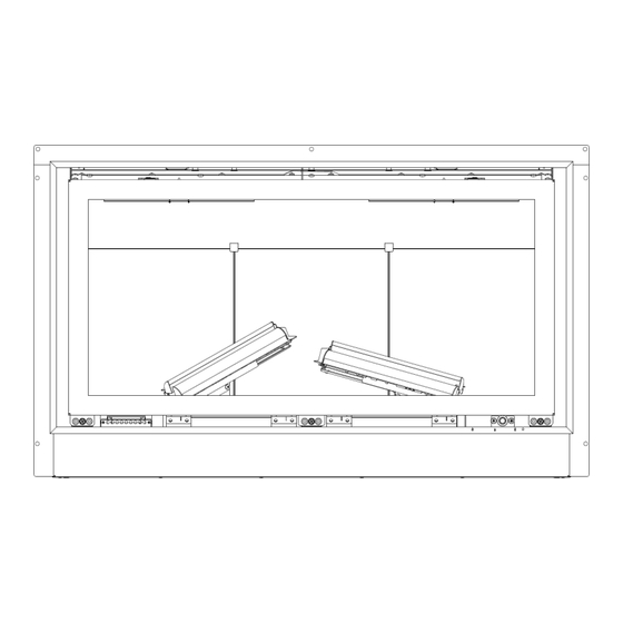
INSTALLATION INSTRUCTIONS Should take place on reassembly after the gas Installing the 4.2 Installing the Burners connection has been made—see page 32 Burners The two upstanding burners need to be installed. They are packed in a carton behind the glass panel and should be prepared for installation. All packaging material should be removed and a check made to ensure that no material has entered the burner venturi. -
Page 32: Connecting The Gas Supply
INSTALLATION INSTRUCTIONS Connecting 4.3 Connecting the Appliance to the Gas Supply To Gas Supply The gas supply should be connected to the appliance by a concealed fitting from the rear. In all installation conditions the gas connection should be provided using 8mm (O/D) copper tubing. -
Page 33: Appliance Data
INSTALLATION INSTRUCTIONS 4.4 Appliance Data Gas Type Natural Gas (G20) Inlet Pressure 20mbar ±1mbar Gas Connection 8mm pipe Injector 2 x 0.98 / 1 x 1.1 / 2 x 1.01 Pilot Body (No Thermocouple) P-XX1318 Thermocouple c/w Microswitch P-XX13182A Input High Rate (Gross) 6.6kW (0.63m /hr) Input Low Rate Slide Control (Gross) -
Page 34: Log Layout Instructions
INSTALLATION INSTRUCTIONS 4.5 The following instructions detail how the ceramic fuel bed and loose components are to be LOG SETUP installed onto the appliance. Great care should be taken when handling these ceramic parts as they are fragile and can easily be broken. Do not force any component into position, if it does not fit easily then you are not fitting the part correctly. - Page 35 INSTALLATION INSTRUCTIONS Place the volcanic rock on top of the centre burner as shown. Ensure a 4-5 mm gap is left FUELBED between each piece. Then using half of the glowing ember wire supplied, ruffle between fingers to make it loose, about 20mm wide and as long enough to cover the volcanic rock then align over the rock as shown.
- Page 36 INSTALLATION INSTRUCTIONS Place Log C onto the right raised burner as shown ensuring it fits securely. Place Log D in the orientation shown ensuring the branch sits just in front of the air hole in the main log as shown. Place Log E in the orientation shown.
- Page 37 INSTALLATION INSTRUCTIONS Place Log F onto the burner bed in front of the centre burner as shown. Place the bark around the fuel bed as shown. Ensure that no bark can interfere with the pilot Bark operation,. Place Log G as shown in the picture.
- Page 38 INSTALLATION INSTRUCTIONS Place Log H onto the burner bed as shown. Place Log I onto the burner bed as shown.
-
Page 39: Controls
INSTALLATION INSTRUCTIONS Controls 4.6 This appliance has a concealed slide control knob. It is discreetly concealed in the space between the decorative trim and the glass door frame on the lower right hand side. Simply press the knob and it will protrude from its current position to enable operation. -
Page 40: Completing The Installation
INSTALLATION INSTRUCTIONS 4.7 Completing the Installation of the Appliance Ensure that the fire operates correctly and that the burners cross light in less than 3 seconds. If cross lighting takes longer than this is or is not consistent, check the location of the two logs B & C. Check that the ember- wire is not interfering with the pilot in anyway as this will cause intermittent lighting problems. -
Page 41: Health & Safety Notice
INSTALLATION INSTRUCTIONS 4.8 HEALTH AND SAFETY NOTICE This appliance uses fuel effect pieces manufactured from Refractory Ceramic Fibres (RCF). Care must be taken to avoid excessive exposure to these materials as they may cause irritation to the eyes, skin, nose and throat. When Handling avoid inhaling and contact with skin and eyes. -
Page 42: Servicing The Appliance
SERVICING INSTRUCTIONS 5.0 Servicing the Appliance. Servicing The following procedures can and should only be performed by a Gas Safe registered installer. This appliance should be serviced annually by a Gas Safe registered installer. Isolate the appliance using the restrictor elbow and remove the 8mm nut from the restrictor as detailed below. - Page 43 SERVICING INSTRUCTIONS Removal of the Burner Tray (Continued) Ensuring the restrictor elbow has been ISOLATED, loosen and remove the inlet nut to release the burner tray from the gas inlet supply. Disconnect the HT Lead from the Igniter. Disconnect the black switch harness plug/socket.
- Page 44 SERVICING INSTRUCTIONS Removal of the Burner Tray (Continued) Remove the six (6) self tapping screws to release the burner tray from the appliance. The burner tray can now be carefully lifted out of the appliance. The following pages detail valve removal/replacement.
-
Page 45: Removal Of The Gas Valve
SERVICING INSTRUCTIONS 5.2 Removal of the Slide Valve Remove the two pipe nuts as shown to allow the pilot gas supply tube to be removed Next, remove the inlet and outlet nuts from the slide valve. Then remove the two screws shown and the thermocouple from the rear of the valve. -
Page 46: Removal Of Pilot
SERVICING INSTRUCTIONS 5.3 Removal of the Pilot Assembly Remove the two pipe nuts as shown to allow the pilot gas supply tube to be removed. Then remove the thermocouple connection from the rear of the slide valve. Next, remove the two screws securing the interrupter microswitch as shown below. Finally remove the two screws holding the pilot burner into place. -
Page 47: Removal Of The Igniter (Spark Generator)
SERVICING INSTRUCTIONS 5.4 Removal of the Igniter (Spark Generator) The gas access covers must first be removed—see page 42. Remove the HT lead and remove the black & white switch connector. Next remove the inner hexagonal screw to remove the heat shield. Then remove the outer hexagonal screw as shown in the diagram below . -
Page 48: Removal Of The Tee Valve (High Setting)
SERVICING INSTRUCTIONS 5.5 Removal of the Tee Valve First remove the inlet and outlet nuts from the Tee Valve as shown in the diagram below. Then remove the two nuts securing the Tee Valve to the underside of the burner tray. The Tee Valve can be removed and replaced. -
Page 49: Removal Of The Injectors
SERVICING INSTRUCTIONS 5.6 Removal of the injectors To reveal the injectors, the burners must first be removed. Remove the four screws at the base of the upstanding burners. The two burners can now be lifted out of the appliance. Take note of the marking on each burner signifying LEFT &... - Page 50 SERVICING INSTRUCTIONS Removal of the injectors (continued) To reveal the final injector, the central burner must now be removed. Remove the three (3) M5 screws marked ‘A’ and the six (6) screws marked ‘B’. Next, remove the two screws shown in the diagram and the central burner can now be lifted from the appliance.
-
Page 51: Inner Side Glass Panel Removal
SERVICING INSTRUCTIONS 5.7 Removal/Replacement of the Two Side Inner Glass Panels First remove the two clips from the top right and top left as shown in the diagram below. These two side panels can now simply be slid out from the appliance. 5.7.1 Removal/Replacement of the Rear Inner Glass Panel Now remove the four screws to allow the two upstanding burners to be removed. - Page 52 SERVICING INSTRUCTIONS Removal/Replacement of the Rear Inner Glass Panel (continued) Now remove the two (2) M5 screws marked ‘A’ and the six(6) self tapping screws marked ‘B’. The bark support plate can now be removed. Pull the black glass panels forward from the base of each panel as shown in the diagram...
-
Page 53: Record Of Annual Services
SERVICING INSTRUCTIONS 6.0 Record of annual services The extended warranty of the specified components within this appliance is conditional on the annual service of the appliance by a Gas Safe registered engineer. Failure to maintain the product or to use the product in away which is not intended will void the manufacturer's warranty. -
Page 54: Product Fiche
7.0 Product Fiche Manufacturer : Be Modern Ltd Model No. BM-191XX2 Fuel Type Natural Gas (G20) I2H Energy Efficiency Class Indirect Heating Functionality Direct Heat Output kW 4.6kW Indirect Heat Output kW 69.1% Useful Energy Efficiency (NCV) High : 78.1% Useful Energy Efficiency (NCV) Nominal Heat Output High : 4.6kW... - Page 55 This page is intentionally left blank...
-
Page 56: Manufacturers Instructions And User Replaceable Spares
Tel: 0191 489 8006 Fax: 0191 580 0085 Email: sales@bemodern.com Due to our policy of continual product improvement, some diagrams and small details may not be accurate however if there is any concern or matter of understanding that you feel needs to be clarified please contact us directly. Our contact details are shown below.
Need help?
Do you have a question about the CALLEOS 800 and is the answer not in the manual?
Questions and answers