Advertisement
Applied Machines: C287/C227/367/287/227
COLOR MFP: 28 ppm/22 ppm
MFP: 36 ppm/28 ppm/22 ppm
Product Code: A797/A798/A789/A7AH/A7AK
1. Accessory parts
No.
Name
1. Hinge cover
(large)
2. Hinge cover
(small)
3. Original mat
4. Shoulder
screw
5. Mounting
screw
6. Chart
7. Installation
manual
Keep this bag away from babies and
children. Do not use in cribs, beds,
carriages, or playpens.
The thin film may cling to nose and
mouth and prevent breathing. This bag is
not a toy.
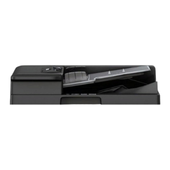
DF-628
Reverse Automatic Document Feeder
INSTALLATION MANUAL
Shape
Q'ty
1
1
1
2
2
1
1 set
Note:
This manual provides the illustrations of the acces-
sory parts and machine that may be slightly differ-
ent in shape from yours. In that case, instead of
the illustrations, use the appearance of your
machine to follow the installation procedure. This
does not cause any significant change or problem
with the procedure.
2. Installation procedures
(1) Turn OFF the power switch and unplug the
power cord from the power outlet.
(2) Hold the Reverse Automatic Document Feeder
as shown in the illustration and remove it from
the carton.
Note:
To prevent breakage, do not hold the Reverse
Automatic Document Feeder by the four corners.
E-1
A7V7-9581-02
Advertisement
Table of Contents

Summary of Contents for Konica Minolta DF-628
- Page 1 DF-628 Reverse Automatic Document Feeder INSTALLATION MANUAL Applied Machines: C287/C227/367/287/227 COLOR MFP: 28 ppm/22 ppm MFP: 36 ppm/28 ppm/22 ppm Product Code: A797/A798/A789/A7AH/A7AK 1. Accessory parts Note: This manual provides the illustrations of the acces- Name Shape Q’ty sory parts and machine that may be slightly differ- ent in shape from yours.
- Page 2 (3) Remove the protective tape and protective mate- (5) Place the Reverse Automatic Document Feeder rials and remove the protective plastic bag of the in position. relay harness. (6) Using two supplied mounting screws, tighten the hinges to secure the Reverse Automatic Docu- ment Feeder in position.
-
Page 3: Adjustment Procedures
4. Adjustment procedures (8) Connect the two connectors of the Reverse Automatic Document Feeder to the main unit, <Adjusting the height> and attach the harness with a cable tie at the position shown in the illustration. (1) Check the clearance between the upper face of scanner and the protrusion on the Reverse Auto- matic Document Feeder side. - Page 4 (2) If there is any clearance, adjust the height by (11) Place the chart in the document feeding tray turning the adjustment screw on the right side (with the side having an arrow facing up). viewed from the back. Clockwise: The rear side will move up. Counterclockwise: The rear side will move down.
- Page 5 <Measuring DF skew> (2) Check “Scale” on the screen, and adjust the + (plus) value by turning the adjusting screw on the (1) Touch “ADF automatic adjustment.” backside clockwise. (2) Touch “Skew Measurement.” Note: (3) Place the chart in the document feeding tray •...
- Page 6 <Affixing the original mat> (4) Touch “END.” (5) Repeat the steps (1) to (6), “Measuring DF skew” (1) Open the Reverse Automatic Document Feeder. described on E-5, to check if the value of “Avg. (2) Using a cleaning pad dampened with alcohol, Value”...
- Page 7 (6) Firmly press the positions where the original mat (14) Confirm whether there is a problem in the is attached with the double-sided tape so that the image. original mat does not peel off. <Auto Stop Position Adjustment> (1) Display the Service Mode screen. (For details of how to display the Service Mode screen, see the service manual.) (2) Touch “ADF.”...
- Page 8 (13) When all the adjustments are completed, set (15) Measure the values “a”, “b” and “c” of the chart the chart to the document feed tray (with the and the sample copy. side with an arrow facing up), and take the When measuring the value “a”, use the sample sample copy at the same magnification.
-
Page 9: Accessory Parts
SP-501 Stamp Unit INSTALLATION MANUAL 1. Accessory parts (3) Open the processing guide. (4) Remove the guide plate. (One screw) Name Shape Q’ty Note: To remove the guide plate, slightly move it to the 1. Stamp unit right as viewed from the front of the machine. 2. - Page 10 3. Configuration procedures (7) Connect the hookup harness connector. (8) Install stamp unit. (Using the screw which has (1) Plug the power cord into the power outlet and been removed in step (5)) turn ON the power switch. Note: (2) Display the Service Mode screen. •...


Need help?
Do you have a question about the DF-628 and is the answer not in the manual?
Questions and answers