Advertisement
Applied Machines: C554e/C454e/C364e/C284e/C224e/C554/C454/C364/C284/C224/C368/C308/554e/454e/364e/
284e/224e
COLOR MFP: 55 ppm/45 ppm/36 ppm/30 ppm/28 ppm/22 ppm
MFP: 55 ppm/45 ppm/36 ppm/28 ppm/22 ppm
Product Code: A5AY/A5C0/A5C1/A5C2/A5C4/A2XK/A4FJ/A161/A4FK/A4FM/A7PU/A7PY/A61D/A61E/A61F/A61G/
A61H
Caution:
Lifting the machine in an awkward position or
transporting it in a poorly balanced position could
result in personal injury. When transporting the
machine, assign an adequate number of persons
to the job and ensure that each person can take a
good position of not being excessively loaded
(mass: approx. 23 kg (50-11/16 lb)).
1. Accessory parts
No.
Name
1. Leg assy
2. Fixing
bracket A
3. Fixing
bracket B
4. Screw
5. Installation
manual
Keep this bag away from babies and
children. Do not use in cribs, beds,
carriages, or playpens.
The thin film may cling to nose and
mouth and prevent breathing. This bag is
not a toy.
PC-410
INSTALLATION MANUAL
Shape
Q'ty
4
3
1
5
1
set
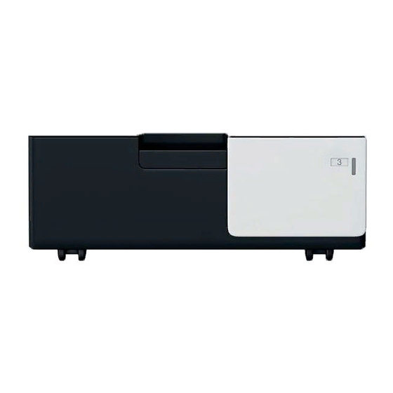
Paper Feed Cabinet
Note:
This manual provides the illustrations of the acces-
sory parts and machine that may be slightly differ-
ent in shape from yours. In that case, instead of
the illustrations, use the appearance of your
machine to follow the installation procedure. This
does not cause any significant change or problem
with the procedure.
Caution:
When removing the paper feed cabinet from its
shipping carton, do not hold the reinforcement
bracket (as a personal injury or a deformed frame
could result).
Reinforcement bracket
E-1
A2XM-9557-00
Advertisement
Table of Contents

Subscribe to Our Youtube Channel
Related Manuals for Konica Minolta PC-410


Summary of Contents for Konica Minolta PC-410
- Page 1 PC-410 Paper Feed Cabinet INSTALLATION MANUAL Applied Machines: C554e/C454e/C364e/C284e/C224e/C554/C454/C364/C284/C224/C368/C308/554e/454e/364e/ 284e/224e COLOR MFP: 55 ppm/45 ppm/36 ppm/30 ppm/28 ppm/22 ppm MFP: 55 ppm/45 ppm/36 ppm/28 ppm/22 ppm Product Code: A5AY/A5C0/A5C1/A5C2/A5C4/A2XK/A4FJ/A161/A4FK/A4FM/A7PU/A7PY/A61D/A61E/A61F/A61G/ A61H Caution: Note: Lifting the machine in an awkward position or...
- Page 2 2. Installation procedures (3) Slide the drawer out. (4) Remove the shipping materials and protective (1) Turn OFF the power switch and unplug the tape from the inside of the drawer. power cord from the power outlet. Note: (2) Remove the protective tape from the paper feed Remove the protective tape A carefully to prevent cabinet.
- Page 3 (7) Holding the transportation handles at the right (8) Peel the tape that fixes the paper feed cabinet and left of the machine, place the machine onto hookup harness in position. the paper feed cabinet. When placing the machine, use the positioning pins in the paper feed cabinet to align the machine correctly with the cabinet.
- Page 4 (12) Slide out the drawer from the paper feed cabi- (17) Attach the four stabilizers (supplied leg assies) net. as shown in the illustration. (13) Slide out the second drawer from the paper Note: feed cabinet. • If you proceed to install the Large Capacity Unit (14) Secure the paper feed cabinet to the machine LU-302/LU-301/LU-204 after this installation, by the fixing bracket A (left) and the fixing...
- Page 5 <Loading paper> <right and rear> (1) Slide the drawer out. (2) Align the edges of the paper stack and place the stack into the drawer. Note: • Make sure that the top level of the paper stack does not exceed the ▼ (MAX) paper level indi- cator.
- Page 6 3. Configuration procedures (7) Slide the drawer out. (8) Loosen the six screws of the drawer (Left: tow <Making settings for paper size> screws, Right: four screws) shown in the illustra- tion. (1) Plug the power cord into the power outlet and turn ON the power switch.
- Page 7 <If you install Finisher FS-535/FS-534SD/FS-534 (8) Move the front cover assy while looking at the after this installation> tick marks on the scales placed near the screws. (5) Measure width A of the test pattern on the back- • If the width A is greater than the specifications: Move the front cover assy to the ➀...
- Page 8 <Centering (Duplex 2nd side)> (1) Touch “Prt. Image Center. Side 2 (Dup).” (2) Touch “3rd.” and then press the Start key. A test print will then be produced. (3) Measure width A of the test pattern on the back- side of the test print produced and check to see if it falls within the specified range.
Need help?
Do you have a question about the PC-410 and is the answer not in the manual?
Questions and answers