
Related Manuals for Uninet UV DTF 3000


Summary of Contents for Uninet UV DTF 3000
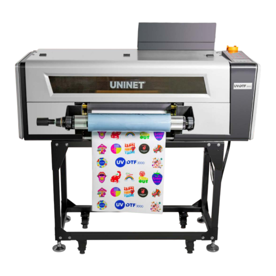
- Page 1 Printer Instruction Manual Please read this manual carefully before use - Keep this book for reference...
-
Page 2: Table Of Contents
Contents 1.Product Introduction .................................2 2. Model specification .................................3 3. B Film holder installation ............................4 3.2 B Film holder installation ..........................5 4. Software installation and setup ..........................6 4.1 Computer configuration requirements .......................6 4.2 Installation of printer control software .....................6 4.2.1 Printing software installation ......................6 4.2.2 IP address set .............................7 4.2.3 Connect Gigabit Network Cable .......................8 4.3 RIP software installation ...........................9... -
Page 3: Model Specification
2. Model specifica�on Model Type UVDTF3000 Print head XP600 Resolu�on 1080DPI 1440DPI Speed High Photo: 2 m Fine Photo: 2 .5m Color control ICC color profile with adjust func�on Print Width 420 mm / 17 inches Opera�on Temperature 25°C-28°C, Humidity 50%-70% Environment Power 50HZ/60HZ 110V 7A... -
Page 4: B Film Holder Installation
3. Printer parts and loca�on 03 Rubber Roller Li�ing 04 Lamina�ng rubber 01 Carriage assembly 02 Control panel Handle roller (hea�ng) 08 Rubber Roller Hea�ng 05 Stepping rubber roller 06 B film holder le� 07 B film holder right Controller 09 Ink Tanks 10 Ink tank holder 11 Switch panel... -
Page 5: B Film Holder Installation
3.2 B film holder installa�on Step 1: Open the packaging box of the machine, remove the cushion foam block and protec�ve film, take out all the accessories and check whether the host and accessories are damaged. Note: If any parts are missing. Step 2: Install the B film holder, install the le�... -
Page 6: Software Installation And Setup
4. So�ware installa�on and setup 4.1 Computer configura�on requirements Computer configura�on requirements: 1. Computer system: Windows 10 64-bit computer system. 2. CPU configura�on: use i5 or above i5 CPU. 3. Memory RAM: 8G or above. 4. Network card: Gigabit or above. 5. -
Page 7: Ip Address Set
4.2.2 IP address set 1. On your PC, find and open the control panel. 2. Select the network and sharing center. 3. Click on “Change Adaptor se�ngs”. 4. Find the corresponding LAN port, Right click Local Area Connec�on and select Proper�es (see image) 5. -
Page 8: Connect Gigabit Network Cable
4.2.3 Connect Gigabit Network Cable You must connect the printer directly to your PC via Ethernet connec�on. Cannot be connected via USB, Wi-Fi, or Bluetooth, nor can it be connected through a router or switch. One end will be connected to the printer mainboard. Connect the other end to the network port of the computer. -
Page 9: Rip Software Installation
4.3 RIP so�ware installa�on 4.3.1 Ac�va�on of RIP so�ware Instruc�ons for ac�va�on of RIP so�ware: Open your web browser and enter the ac�va�on website in the browser htps://www.saicloud.com Enter the ac�va�on code box on the so�ware box label a�er entering the webpage. Select ‘I am new to the SAi Cloud’, enter your email address and create an account. - Page 10 Click Ac�vate Now. Once ac�vated, install the USB drive included with package.
-
Page 11: Rip Software Installation
4.3.2 RIP so�ware installa�on Install the USB drive, open the Autorun executable file in the directory, select the installa�on language, accept the so�ware license agreement and set the so�ware installa�on directory. - Page 12 When installing, make sure the laptop/PC is connected to the Internet. The so�ware will connect to the SAi cloud to verify the license has been ac�vated. A�er the comple�on dialog box pops up, the so�ware installa�on is completed.
-
Page 13: Rip Software Setup And Use
4.3.3 RIP so�ware setup and use 1. To prepare ICC profiles, green USB Drive you will find the ICC profiles. Extract the folder to your desktop. 2. Prepare Flexi Product Manager se�ngs. Run icon For new installa�ons, the so�ware will pop up the add device op�on automa�cally. For exis�ng installa�ons Open the so�ware, click "Se�ngs"... - Page 14 3. Se�ng up the Job Proper�es Click "Setup" in the menu bar then click "Default Job Proper�es" 4. Select "Layout" tab. - Change the width size to 16 inches. 5. Select “WorkFlow” tab. - Change the “a�er output” to “Hold” to keep the job in the queue a�er saving. Leaving it in delete will delete it a�er saving.
- Page 15 6. Select “Color Management” tab. - Press the “Add” buton for the "Output Configura�on Field. Search for the ICC extracted folder and select the two ICC configura�on file, and then add the ICC files. - In the Media field select the matching ICC profile as in the Output profile feed. They need to match or an error symbol will appear.
- Page 16 7. Se�ng up the Choke and the Bleed. - Click on the “Choke” Buton - Select the spot 1 line and press “Edit” White spot color choke func�on: choke---spot 1---Type: choke, distance: 0.1mm (modified according to different needs) - Select the spot 2 line and press “Edit” Varnish spot color bleed type: choke--spot 2 --- Type: Bleed, distance: 0.3mm (modified according to different needs) Spot_1:White spot Spot_2:Varnish spot...
- Page 17 10. Save the preset name and set it as the default job atribute. Set different se�ngs on the preset, which can be saved as different names. Once all the parameters are set, click "OK" to save the se�ngs.
- Page 18 Impor�ng artwork: Open the "Job" icon on the main interface of the so�ware, and directly add the print image file. Nest Jobs: When there are mul�ple pictures that need to be printed together, a�er adding mul�ple pictures, select the picture that needs to be typeset together, and then right-click the mouse to select "Nest Jobs".
-
Page 19: Initial Machine Set Up
4.4 Ini�al Machine Set up Before machine is powered on, the carriage must be released by removing the “L” bracket. Using the Allen key included with the spare parts box, remove the screw shown below. Once the L bracket is removed along with the screw and foam, manually move the carriage to the center of the printer. -
Page 20: Ink Tank Installation
4.4.1 Ink tank installa�on 1. Install and fix the screws on the main ink tank bracket, then put the ink tanks in order, and connect the corresponding color ink tanks and the corresponding marked ink tubes. 2. The ink tank of white ink is connected to the power cord of the white ink s�rring motor. 3. -
Page 21: Button Settings And Instructions
4.4.2 Buton se�ngs and instruc�ons 1:Printer table ligh�ng 2:Rubber roller heater switch 3:Printer power supply switch 4: Rubber roller hea�ng temperature se�ng and regulator (Usually the hea�ng temperature is set at 40-60℃) 4.4.3 Establishing a Link Between Printer and So�ware Turn printer ON. -
Page 22: Priming The Dampers
4.4.4 Priming the Dampers Make sure the printer is in the home posi�on, with the capping sta�on locked to the carriage. Using a syringe and green �p, suc�on the waste lines coming from the damper system. Con�nue suc�on un�l ink reaches the syringe. 3 out of the 4 hoses will release ink. The 3rd will not because it is not locked to a print head. - Page 23 2. Use the adjustment knob to shi� the holder from le� to right to center the roll. 3. Tension the A Film holders by rota�ng the tension knob on the right and le� of the film holder. First, release the tension completely by turning the knob Counter Clockwise un�l it stops.
- Page 24 4. The film needs to be centered when entering the printer, roughly 1 ¾ inch space on the Right and Le� of the film. Film should go over the first free spinning roller and under the second adjustable roller. This will insure you clear the proximity sensor that detects the film.
- Page 25 7. Pull at least 2 feet of film between the rollers. Grabbing the film, pull in your direc�on while shi�ing the film to the right and le� to feel for the center. Where the tension is even on the right and the le�. Once its centered, lower the rubber heat rollers to pinch the film in place.
- Page 26 8. Check that the film if feeding straight by pressing and holding down the “Down” buton on the control panel. Feed about 1 to 2 feet of A Film. Check the prin�ng area if the film is “li�ing” from both right or le� side of the film. 9.
- Page 27 Rear film rollers: 10. Once the film is posi�oned correctly and tensioned install the laminate and laminate sha�. Install the Laminate roll (B Film) on the roll sha�. The laminate is posi�oned on the front of the printer. The le� side is installed first to interlock the holder.
- Page 28 11. The laminate roll is ½ inch wider than the A Film. Use the slack of the A Film to align the B Film, it needs to exceeds the A Film on both sides.
- Page 29 12. Once aligned redirect the A Film to fall downward a�er the passing the rubber heat rollers. The B Film is installed with the film unwinding from the botom of the roll. It while go over the aluminum free spinning roller. 13.
- Page 30 14Hold the B Film against the rubber heat roller while pressing the “Down” buton on the control panel. Be careful not to pinch your fingers when the roller rotates. 15Check that the B Film overlaps the A film a�er the rubber heat rollers. 16.
- Page 31 17. Once the calibra�on is finished, reveal the adhesive by cu�ng the top of the A Film using a blade. Cut deep enough to only cut the clear film. Do not cut the white A Film. 18. Pull the clear film over the aluminum roller and pass it to the back of the printer. Tape the clear film to the rear rewinder.
- Page 32 4.5 Print head installa�on posi�on and cable connec�on 4.5.1 Print head installa�on Note: Printheads will be pre-installed. The following is only for reference. Skip to 4.6 Calibra�on. 1. Cable installa�on, the print head cable is one 29P cable on the le� and right. (Note: Be careful when plugging in to avoid damaging the printhead or cables!) A�er the cable is plugged in, the cable interface is sealed with tape to prevent foreign objects or ink from entering the cable interface.
- Page 33 2. Print head installa�on (H2 white print head) Put the print head to the le� and back, close to the botom plate, and install and secure it with the screws. (Note: do over �ghten the print head moun�ng screws) The print head and the damper are connected, and the ink sequence is set: First connect the damper to the corresponding ink tube, and then use a syringe to pump the ink from the ink tube to the damper.
-
Page 34: Print Head Data Cable Connection Adapter Board
4.5.2 Print head data cable connec�on adapter board The connec�on sequence of the data cable corresponds to the markings on the head board and the print head in turn (Note: Plug and unplug the print head data cable must be operated with the power turned off.) H1-C: color, H2-W: white, H3-Vr: glue, H4-V: varnish. - Page 35 Le� Right Right Le� Tidy up the cables: H1-C H4-V H2-W H2-W H1-C H4-V A�er confirming that the data cable of the print head is connected correctly, turn it on and observe whether the "ERROR" light on the head board is on. If the light is on, it is abnormal. Power off immediately and check.
-
Page 36: Debug Before Printing
4.6 Calibra�ng the Printheads before Prin�ng 4.6.1 Print nozzle test Connect the machine to the power supply and launch the prin�ng so�ware interface. (Note: the ink stack should be close to the nozzle a�er the machine self-check is completed) Click the “Load ink” icon to confirm that ink is flowing out of the waste ink tube, and click the fill ink icon again to cancel. -
Page 37: Vertical Alignment Of The Print Head
4.6.2 Ver�cal alignment of the print head Enter the so�ware op�on ”Adjust” interface and align the print head ver�cally “Print Adjust”. For ver�cal calibra�on, the ver�cal direc�on of the If there is a devia�on, loosen the fixing screw of the test chart required to be printed is a straight line. -
Page 38: Calibration Of Nozzle Horizontal Space
Print Adjust again and confirm that the line at the value 0 is the most uniform. Click the "Save" buton in the upper right corner. 4.6.4 Calibra�on of nozzle horizontal space Calibra�on of the horizontal distance between the print heads,Print Adjust. The calibra�on chart is at the value +2, and the lines completely overlap. -
Page 39: Nozzle Vertical Space Calibration
Then calibrate the direc�on to the right, the steps are the same as above. 4.6.5 Nozzle ver�cal space calibra�on Calibra�on of ver�cal spacing between nozzles. Print Adjust. The calibra�on chart is at the value -2, and the lines completely overlap. In the corresponding print head, increase or decrease the corresponding value in the input box of the corresponding prin�ng direc�on. -
Page 40: Bidirectional Printing Calibration
4.6.6 Bidirec�onal prin�ng calibra�on Finally, perform bidirec�onal prin�ng calibra�on, Print Adjust. The calibra�on chart is at the value -3, and the lines completely overlap. Select the corresponding prin�ng speed, and increase or decrease the corresponding value according to the calibra�on chart. Print Adjust again and confirm that the line at the value 0 is the most uniform. - Page 41 Shortcuts Func�on descrip�on Shortcut Prin�ng start buton to execute the print command Print head check buton to execute print head prin�ng state Prin�ng pause/resume buton Prin�ng cancel buton to execute the end prin�ng command...
- Page 42 Print head cleaning buton to execute print head cleaning command Flash spray on/off buton White edge posi�oning buton Moisturizing off/on buton Reset buton X motor le� shi� buton X motor right shi� buton Feed buton Return buton Stepping fine adjustment reduc�on buton Stepping fine adjustment increase buton Two-way fine adjustment reduc�on buton Two-way fine adjustment increase buton...
-
Page 43: Precautions For Printing Equipment
Network cable disconnec�on Offline Turn on the flash spray Turn off the flash spray System func�ons normally System error System warning Offline Normal print head temperature Abnormal print head temperature print head temperature warning Offline 5.Precau�ons for prin�ng equipment 5.1 Recommenda�ons for the process requirements of the film-passing machine 1. -
Page 44: Maintenance Of Printing Equipment
2. The film is passed twice: The first �me the film is cold-pressed at room temperature The second 35 ℃ temperature pressing through the film 3. Film speed: 3-5CM/S 5.1 Maintenance of prin�ng equipment A�er star�ng the machine, the nozzle must be cleaned. Print a test strip once for each switch on and off.
Need help?
Do you have a question about the UV DTF 3000 and is the answer not in the manual?
Questions and answers