Table of Contents
Advertisement
Quick Links
Advertisement
Table of Contents

Related Manuals for Uninet UV DTF 3000


Summary of Contents for Uninet UV DTF 3000
- Page 1 UV DTF 3000 A2 UV Printer Instruction Manual...
-
Page 2: Table Of Contents
Contents 1.Product Introduction ................................3 2. Model specification ................................3 3. Product show and rack installation ..........................4 3.1 Product show ................................4 3.2 Rack installation ..............................5 4. Software installation and setup ..........................6 4.1 Computer configuration requirements ....................... 6 4.2 Installation of printing software ........................6 4.2.1 Printing software installation ...................... -
Page 3: Product Introduction
It is suitable for a wide range of applications and is the best choice for individuals, small and medium-sized enterprises. Model specification UV DTF 3000 Model Type Print head XP600... -
Page 4: Product Show And Rack Installation
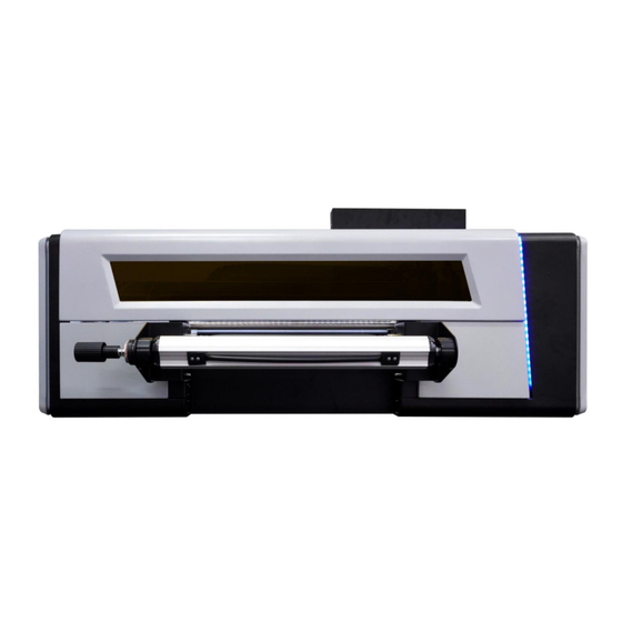
3. Product show and rack installation 3.1 Printer Parts 03 Rubber Roller Lifting 04 Laminating rubber 01 Carriage ink stack assembly 02 Control panel Handle roller (heating) 08 Rubber Roller Heating 05 Stepping rubber roller 06 B film holder left 07 B film holder right Controller 09 Ink tank Rewinding tray... -
Page 5: Rack Installation
3.2 ROLLER RACK INSTALL Step 1: Open the packaging box of the machine, remove the cushion foam block and protective film, take out all the accessories and check whether the host and accessories are damaged and whether the appearance is worn. Note: Random accessories, check carefully to prevent them from being lost! Step 2: Install the feeding holder , install the left and right feeding holder separately, and fix them with screws. -
Page 6: Software Installation And Setup
4. Software installation and setup 4.1 Computer configuration requirements Computer configuration requirements: 1. Computer system: Windows10 or above 64-bit computer system. 2. CPU configuration: use i5 or above CPU. 3. Memory stick: 8G or above. 4. Network card and network cable requirements: Gigabit or above network card must be used, and the network cable needs to be super Category 6 or above to support dry-mega communication network cable. -
Page 7: Ip Address Set
4.2.2 IP address set Open the desktop computer, find the control panel to enter, and then select the network and sharing center. Find the corresponding LAN port, click Local Area Connection, select Properties—Internet Protocol Version 4, and then click OK. Click to use the following IP address, set the IP address to 192.168.127.11, and the subnet mask to 255.255.255.0, and then click OK. -
Page 8: Rip Software Installation
4.3 RIP software installation 4.3.1 Activation of RIP software Instructions for activation of RIP software: Start the browser and enter the activation website in the browser https://www.saicloud.com press enter and enter the activation code box on the software box label after entering the webpage. Select I am a new user, enter the email address and create an account, a confirmation email will be sent to the mailbox. - Page 9 Click Activate Now, click the Download License button to download the license file...
-
Page 10: Rip Software Installation
4.3.2 RIP software installation Put the installation CD into the CD-ROM drive or open the USB disk, open the Autorun executable file in the directory, select the installation language, accept the software license agreement and set the software installation directory. - Page 11 When installing to the pop-up license dialog box,If the currently installed computer cannot be connected to the Internet, directly import the previously downloaded license file. If the current computer can access the Internet, you can enter the activation code to complete the licensing process or click "Get Authorization from Website"...
-
Page 12: Rip Software Setup And Use
4.3.3 RIP software setup and use 1.Driver file replacement First open the software installation location disk folder, find the path of the driver folder: \Program Files (x86)\SAi\FlexiPRINT 19 Titan Edition\OutputDrivers, copy and paste all the new driver files into the "OutputDrivers" folder (copy and replace ). - Page 13 Select "Color Management"-"Output Configuration File"-"Add", select the corresponding ICC configuration file, and then add the ICC. 4. Set the default job properties Click "Setup" in the menu bar-"Default Job Properties..." Some general default job properties are set as follows: [Layout]: The media size and width are set according to the width of the printing film, and the height is the default value. [Workflow]: After outputting, set to Hold.
- Page 14 [Color Management]: Choose a different preset mode on the preset, and the color correction will be changed to a different curve accordingly. White spot color choke function: choke---spot 1---Type: choke, distance: 0.1mm (modified according to different needs) Varnish spot color bleed function: choke--spot 2 --- Type: Bleed, distance: 0.3mm (modified according to different needs) Glue spot color bleed function: choke--spot 3 --- Type: Bleed, distance: 0.4mm (modified according to different needs) Spot_1:White spot Spot_2:Varnish spot...
- Page 15 5. Save a preset name and set it as the default job attribute. Customers can adjust the parameters according to their own needs and choose the corresponding ICC profile. Set different settings on the preset, which can be saved as different names. Finally, after all parameters are set, click "OK"...
- Page 16 Job attributes: 1. Job size, you can scale the picture size according to your needs; (to check manual nesting) 2. Position, the distance setting from picture to page edge and header; (to check manual nesting) 3. Copies, you can copy multiple pictures and typeset at the same time according to your needs; 4.
-
Page 17: Machine Power Detection
4.4 Machine power detection 1. Power safety Note: For the safety of people and machines, be sure to connect the ground wire! Use a digital multimeter to measure whether the power supply voltage is normal, and the range of live and neutral measurement values: 120VAC (the multimeter is set to 200V AC gear). -
Page 18: Ink Tank Installation
4.4.1 Ink tank installation 1. Install and fix the screws on the main ink tank bracket, then put the ink tanks in order, and connect the corresponding color ink tanks and the corresponding marked ink tubes. 2. The ink tank of white ink is connected to the power cord of the white ink stirring motor. 3. -
Page 19: Button Settings And Instructions
4.4.2 Button settings and instructions ①:Printer table lighting ②:Rubber roller heater switch ③:Printer power supply switch ④ : White ink circulation pump speed adjustment knob (Usually set up 40-50%) ⑤ : Rubber roller heating temperature setting and regulator (Usually the heating temperature is set at 40-60℃) -
Page 20: Print Head Installation Position And Cable Connection
4.5 Print head installation position and cable connection 4.5.1 Print head installation 1. Cable installation, the print head cable is one 29P cable on the left and right. (Note: Be careful when plugging in to avoid damaging the printhead or cables!) After the cable is plugged in, the cable interface is sealed with tape to prevent foreign objects or ink from entering the cable interface. - Page 21 3. Print head installation (H2 white print head) Put the print head to the left and back, close to the bottom plate, and install and fix it. (Note: do not fix the print head mounting screws too hard) The print head and the damper are connected, and the ink sequence is set: first connect the damper to the corresponding ink tube, and then use a syringe to pump the ink from the ink tube to the damper.
-
Page 22: Print Head Data Cable Connection Adapter Board
4.5.2 Print head data cable connection adapter board The connection sequence of the data cable corresponds to the markings on the head board and the print head in turn (Note: Plug and unplug the print head data cable must be operated with the power turned off.) H1-C: color, H2-W: white, H3-Vr: glue (Not used) H4-V: varnish. - Page 23 Tidy up the cables: H1-C H4-V H3-Vr H2-W H3-Vr H2-W H1-C H4-V After confirming that the data cable of the print head is connected correctly, turn it on and observe whether the "ERROR" light on the head board is on. If the light is on, it is abnormal. Power off immediately and check.
-
Page 24: Debug Before Printing
4.6 Debug before printing 4.6.1 Print nozzle test Connect the machine to the power supply and enter the printing software interface. (Note: the ink stack should be close to the nozzle after the machine self-check is completed) Click the “Load ink” icon to confirm that ink is flowing out of the waste ink tube, and click the fill ink icon again to cancel. -
Page 25: Step Calibration
4.6.3 Step calibration Step calibration, Print Adjust. The calibration chart is at the value -2, and the lines completely overlap. So enter the value -2 in the corresponding input box, and then click Calculate. Print Adjust again and confirm that the line at the value 0 is the most uniform. Need to click the "Save" button in the upper right corner. -
Page 26: Calibration Of Nozzle Horizontal Space
4.6.4 Calibration of nozzle horizontal space Calibration of the horizontal distance between the print heads, Print Adjust. The calibration chart is at the value +2, and the lines completely overlap. In the corresponding print head, increase or decrease the corresponding value in the input box of the corresponding printing direction. -
Page 27: Nozzle Vertical Space Calibration
4.6.5 Nozzle vertical space calibration Calibration of vertical spacing between nozzles. Print Adjust. The calibration chart is at the value -2, and the lines completely overlap. In the corresponding print head, increase or decrease the corresponding value in the input box of the corresponding printing direction. -
Page 28: Bidirectional Printing Calibration
4.6.6 Bidirectional printing calibration Finally, perform bidirectional printing calibration,Print Adjust. The calibration chart is at the value -3, and the lines completely overlap. Select the corresponding printing speed, and increase or decrease the corresponding value according to the calibration chart. Print Adjust again and confirm that the line at the value 0 is the most uniform. -
Page 29: Background Factory Settings
4.6.7 Background factory settings Password: generally model:111111 Factory model:Ctrl+F12 into factory model,then enter password:222222 Version information Click the version information in the advanced interface and enter the following interface: Change key panel language Select advance-encryption-language.as shown below. - Page 30 Change waveform Advance-enter password Into factory model Select wareform setting ,default waveform. Shortcut button Shortcut Function description Printing start button to execute the print command print head check button to execute print head printing state Printing pause/resume button Printing cancel button to execute the end printing command print head cleaning button to execute print head cleaning command Flash spray on/off button...
- Page 31 White edge positioning button Moisturizing off/on button Reset button X motor left shift button X motor right shift button Feed button Return button Stepping fine adjustment reduction button Stepping fine adjustment increase button Two-way fine adjustment reduction button Two-way fine adjustment increase button Status bar Status bar icon Description...
- Page 32 Offline Turn on the flash spray Turn off the flash spray System functions normally System error System warning Offline Normal print head temperature Abnormal print head temperature print head temperature warning Offline...
-
Page 33: Precautions For Printing Equipment
5.Precautions for printing equipment 5.1 Recommendations for the process requirements of the film-passing machine 1. Pressure: 0.6MPa 2. The film is passed twice: The first time the film is cold-pressed at room temperature The second 35 ℃ temperature pressing through the film 3.
Need help?
Do you have a question about the UV DTF 3000 and is the answer not in the manual?
Questions and answers