Table of Contents
Advertisement
Quick Links
Advertisement
Table of Contents

Related Manuals for LAI Games Sonic Beat


Summary of Contents for LAI Games Sonic Beat
- Page 1 SONIC © LAI Games 2000 INSTRUCTION MANUAL...
- Page 2 LEISURE & ALLIED INDUSTRIES Correspondence regarding this machine should be addressed to your closest LAI Games Distributor, or Leisure and Allied Industries office. For a list of Leisure and Allied office contact details, refer to the back page of this manual.
-
Page 3: Table Of Contents
TABLE OF CONTENTS INTRODUCTION …………….….….…………….….………………. Specifications ………….……………………….……………….. Caution ……….…………………………………….…………… Handling precautions ………….………….……..……………… How to play ……………...…….………….……..……………… OPERATION …………………….……………………………………. TEST MODE ……………………………………….…………….…… Sound, Light & Display Test …………………………………… Switch Test ………….……….………….………….…………… Prize Arm, Lights & Motors Test ………….…………..……….. PROGRAMMABLE ADJUSTMENTS MODE …………………….. Programmable Adjustments Quick Reference Table ……….….. - Page 4 SECTION B – TECHNICAL DETAILS MAINS VOLTAGE ADJUSTMENT …….…….…………………….. “SONIC BEAT” PARTS LIST ……….…………………….………… CABINET WIRING DIAGRAMS …………………………………… Main Cabinet wiring ………….………………………………… Power Distribution …………….………………..………………. Optional Extras wiring …………………………..……………… WARRANTY ……….……….……….………………… Back inside cover LAI GAMES OFFICES & CONTACT DETAILS …..……... Back cover...
-
Page 5: Introduction
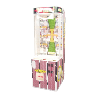
CONGRATULATIONS! You have just bought “Sonic Beat”. Another sensational product from LAI games. This is, in our opinion, one of the best prize vending games made in the world. It is very simple, yet challenging to play with a fast action play style that is hard to resist. -
Page 6: Specifications
SPECIFICATIONS DIMENSIONS !" Weight: 140kg (310lb) !" Height: 2000mm (78.½") !" Width: 640mm (25") !" Length: 770mm (30.½") !" Power: Maximum 450w – (220V @ 2·2A)(120V @ 3.8A) Average 300w – (220V @ 1·4A)(120V @ 2·5A) ELECTRIC SUPPLY !" The game has the option to operate on a 120V, 220V, 240V AC 50/60Hz mains electric supply. -
Page 7: Caution
!" The Cabinet should be grounded with a securely connected ground line. DO NOT Subject the “Sonic Beat” to extreme temperature variations. Reliability of electrical components deteriorates rapidly over 60 DO NOT Expose the game logic boards to U.V. radiation (eg. direct sunlight) as this could eventually corrupt the program. -
Page 8: Handling Precautions
HANDLING PRECAUTIONS When installing or inspecting the machine, be very careful of the following points and pay attention to ensure that the player can enjoy the game safely. !" Be sure to turn the power OFF before working on the machine. !"... -
Page 9: How To Play
HOW TO PLAY THE PLAYER’S AIM IS TO STOP THE MOVING BAR ON THE RED “WIN” ZONE !" Insert coins. !" Press the Start/Stop button to begin the game. A moving bar will begin to move up and down the LED display !"... -
Page 10: Operation
OPERATION !" The “Sonic Beat” game has six operational modes: Attract mode, Play mode, Test Mode, Programmable Adjustments Mode, Audits Mode and Score History Mode. POWER UP ATTRACT MODE PLAY MODE Press NOTE: Entering test mode will lose TEST any unplayed credits. -
Page 11: Test Mode
TEST MODE The Test mode has three test configurations allowing you to test the function of the Sound, LED & Credit Displays, the Game Switches, and to test the Prize Arm Lights & motors. (Refer to Diagram below). Test mode can also be used for Clearing Game Errors, Setting Game Options and Checking Game Audits &... -
Page 12: Switch Test
ADDITIONAL TEST BUTTON INFORMATION ∗ The test button is also used for DISPLAYING & CLEARING ERRORS. more information refer to Errors & Troubleshooting Page 22. ∗ Entering Test Mode will CLEAR any CREDITS remaining in the game. ∗ If during test mode no ADJUSTMENTS or actions are made to the game for approximately four minutes, it will automatically RETURN to Attract Mode. - Page 13 ♦ Normal condition for the game is either: ∗ indicating that no switches are active, or ∗ indicating that the Ticket Notch is active (If optional Ticket Dispenser is fitted). NOTE: Several switches can be simultaneously activated in Switch test. The display will then consecutively show their codes, indicating which switches are active.
-
Page 14: Programmable Adjustments Mode
PROGRAMMABLE ADJUSTMENTS MODE GAME ADJUSTMENTS ♦ The game has thirteen programmable adjustments that can be changed in this mode. They are P01 to P14 and their codes and values are displayed alternatively during the adjustment procedure. Example: displayed adjustment alternates with its value Refer to the diagram below: TEST MODE Press... -
Page 15: Programmable Adjustments Quick Reference Table
PROGRAMMABLE ADJUSTMENTS QUICK REFERENCE TABLE PROGRAMMABLE OPTIONAL DEFAULT CODE FEATURES ADJUSTMENTS VALUES SETTINGS 1 – 10 1, 2, 3…10 Coin Slot 1 – Coins / Credit 1 – 10 1, 2, 3…10 Coin Slot 1 – Games / Credit Coin Slot 1 0 –... -
Page 16: Programmable Adjustments Detailed
PROGRAMMABLE ADJUSTMENTS DETAILED P01 = COIN MECH 1: NUMBER OF COINS PER CREDIT !" (default 01) (Adjustable 1 – 10) This variable sets the number of coins that need to be inserted for each credit. It can be set to either of 1, 2, 3… to 10 coins for one credit. P02 = COIN MECH 1: NUMBER of PLAYS PER CREDIT !"... - Page 17 P09 = ATTRACT MODE SOUND !" (default 01) (Adjustable ON or OFF) This adjustment turns the attract mode sound ON or OFF. This is the sound and music that the game generates to attract customers when it is not being played. The music cycles approximately every 4 minutes.
-
Page 18: Audits Mode
AUDITS MODE !" By using the Audits Mode the operator can view statistics in all areas of the Game Play. This enables the operator to make calculated adjustments and “Fine Tune” the machine to maximize earning potential. !" The Audits mode allows bookkeeping of the games processed since the last game audits reset. -
Page 19: Game Audits Quick Reference Table
GAME AUDITS QUICK REFERENCE TABLE DISPLAY CODE GAME AUDITS No. of prize selections on Arm 1 No. of prize selections on Arm 2 No. of prize selections on Arm 3 No. of prize selections on Arm 4 No. of prize selections on Arm 5 No. -
Page 20: Game Audits Detailed
GAME AUDITS DETAILED A01 = TOTAL PRIZE ARM 1 !" This Audit displays the total number of Prizes selected from “Prize Arm 1” since the audits were last cleared. (For position of Arm 1, refer to diagram Page 17). A02 = TOTAL PRIZE ARM 2 !"... - Page 21 A10 = TOTAL GAMES LOST !" This Audit displays the total number of Games that have not won a prize since the audits were last cleared. A11 = TOTAL GAMES PLAYED !" This Audit displays the total number of Games Played since the audits were last cleared.
-
Page 22: Score History Mode
SCORE HISTORY MODE !" By using the Score History Mode the operator can view the score for the last five Attempts of the Games Played. This enables the operator to verify player win results. ■ ENTER The Score History is entered from Audits Adjustments mode by pressing the Test button once, or from Attract mode by pressing the Test button Six times. -
Page 23: Fitting Prizes To The Prize Arm
FITTING PRIZES TO THE PRIZE ARM STEP ONE: Removal of Prize Locking Pin. Unscrew the Prize Locking pin (left- hand thread), by turning it in a clockwise direction. Remove the pin by pulling it all the way out. STEP TWO: Attachment of Hanging Ties. !"... - Page 24 STEP FOUR: Correct positioning of prizes. !" Position the Hanging Ties on the START prize arm as shown. Space the prizes apart on the arms so they present well FINISH looking from the front. Ensure the prizes do not restrict the viewing of the 4-digit display.
- Page 25 PRIZE SELECTION AND PAYOUT ADJUSTMENT Please read the following guide as a good “starting point” for setting up of your new “Sonic Beat” machine. By testing different merchandise and fine tuning the settings you can maximize your game earnings. * NOTE: All the following recommendations are based on an approximate payout of 30%.
-
Page 26: Errors & Troubleshooting
P13 is set to [ 0 ]. an optional extra. EEPROM ERROR Send MCU PCB to the closest Err3 Problem with on-board EEPROM. LAI Games distributor for repair. PRIZE ARM EMPTY or PRIZE SENSOR NOT Refill Prize Arms or test sensor Err4 WORKING using switch test. - Page 27 The game will then payout any owed tickets. * NOTE: The ticket dispenser is an optional extra for “Sonic Beat”, so if a Err1 error occurs and NO ticket dispenser is fitted to the game, check program adjustment P13 is set to [ 0 ].
- Page 28 !" Err6 = AUTOMATIC CAN NOT MAKE PRIZE WINS HARDER. This error will only be displayed when entering test mode. It occurs only when programmable adjustment P08 is in automatic mode ON. The game has set the Game Difficulty the most difficult setting possible and still can not achieve the desired win per Games as set in programmable adjustment P12.
-
Page 29: Fuses
FUSE LIST FUSES LOCATION DIAGRAM As viewed from rear DC DRIVER FUSES 2 x 5 AMP FAST BLOW PRIZE CHUTE CPU POWER FUSE 2 AMP FAST BLOW MAIN AC 24V AC SUPPLY FUSE SUPPLY (FOR 6 AMP LED DISPLAY) FUSE 3 AMP FAST BLOW SLOW BLOW... -
Page 30: Fuses Detailed
FUSES DETAILED For location of Fuses, please refer to the diagram on page 25 of this manual. !" DC DRIVER FUSES (2 x 5 AMP M205 Fast Blow). These two fuses are for all the DC controlled motors and counters. These include the motors of the prize arms in the prize display, the coin and prize counters and also the optional ticket dispenser Motor Drive. -
Page 31: Section A - Service Instructions
SECTION A SERVICE INSTRUCTIONS Please read these instructions carefully before servicing this machine. -
Page 32: Locating And Accessing Parts
LOCATING & ACCESSING PARTS PARTS LOCATION DIAGRAM As viewed from rear PRIZE ARMS PRIZE ARMS NUMBERS NUMBERS 1 TO 4 LED DISPLAY 5 TO 8 PCB’S PRIZE CHUTE MCU CONTROLLER (GAME PCB) TILT SENSOR PRIZE SENSOR PCB’S SOUND PCB POWER SUPPLY AMPLIFIER FLUORESCENT POWER INLET... -
Page 33: Power Cord
POWER CORD !" The power cord is a standard IEC power cord (as used on computers) that is plugged in to the power inlet socket at the rear of the machine. The power cord can be removed for transport. COIN MECHANISM !"... -
Page 34: Transformers
POWER INLET !" The power inlet is located at the rear of the machine on the Left-hand side as viewed from the rear. It is a standard IEC inlet socket. MAINS SWITCH !" The mains switch is located on the power inlet assembly along with the mains fuse, and IEC inlet socket. -
Page 35: Ticket Dispenser
These are standard dichroic lamps and are accessed from the prize display through the prize display door. !" SONIC BEAT DISPLAY MYLAR LAMP: There is one standard FL 15 fluorescent tube for the display mylar. It can be accessed through vents on the top of the machine, or by removing the mylar and accessing the tube from the front. -
Page 36: Maintenance
MAINTENANCE CLEANING AND CHECK UP * NOTE: Do not use solvents on the Perspex panels as it may affect the plastic. !" EXTERIOR Dust regularly and clean the external cabinet areas as required, using a soft water- damp cloth and mild soap. Check for blown bulbs and replace as required. ♦... -
Page 37: Optional Extras
OPTIONAL EXTRAS TICKET DISPENSER !" There is an optional ticket dispenser available to operate with “Sonic Beat”. It is fitted to the cabinet under the coin door. A hole must be cut in the cabinet to fit it. !" Wiring of the ticket dispenser is shown in the wiring diagrams in this manual Page !"... -
Page 38: Section B - Technical Details
SECTION B TECHNICAL DETAILS It is advised that anybody using SECTION B for repairing or modifying any of the components of the game should be a qualified technician, having at least a basic knowledge of digital components, integrated circuits and electricity. -
Page 39: Mains Voltage Adjustment
MAINS VOLTAGE ADJUSTMENTS TRANSFORMER CONNECTOR !" Locate the 2 machine transformers in the base of the cabinet. If unsure of the location of either transformer, refer to Parts location diagram on page 27 of this manual. !" Change the position of the ‘ACTIVE’ or ‘HOT WIRE’ input, (marked brown on the diagram), to the position for the desired mains voltage. -
Page 40: Sonic Beat Parts List
SONIC BEAT PARTS LIST Product Description CODE Artwork Material Sticker Warning High Voltage SP-AT0001 Sticker Warning Turn Off SP-AT0003 Sticker Service Panel Set SP-AT0103 Acrylic SB Prize Door "Push" SP-AT2601 Sticker SB Cabinet Front Lower SP-AT2603 Sticker SB Cabinet Sides L&R... - Page 41 Terminal JST Connector Pin SP-EA0601 Terminal Molex Edge Connector Pin SP-EA0602 Terminal Screw Block 4 x Terminals SP-EA0614 Terminal Utilux Connector Female No. ST 730206-3 Pins SP-EA0615 Terminal Utilux Connector Male No. ST 750208-3 Pins SP-EA0616 Transformer Multi Tap / 2 x 12v 5A (SNJ) SP-EA0808 Transformer Multi Tap /Out Tap 12,18,24,30v 5A (SB) SP-EA0817...
- Page 42 Hardware Material Coin Mech Holder Assy Single for Coin Door SP-HA0014 Castor Wheel 2" Swivel SP-HA0016 Assembly SB Display Door Frame PC White (w/o Glass) SP-HA2034 Assembly SB Led Display Panel SP-HA2701 Assembly SB Display Door PC White (w/o Glass) SP-HA2706 SB Upper &...
-
Page 46: Warranty
WARRANTY LAI warrants its manufactured products (LAI Games) sold by them for a period of 3 months from the date of sale. LAI’s exclusive obligation is to repair any item with any defects as a result of faulty workmanship or materials, providing the defective item or items of equipment are returned to the LAI office from which the machine was purchased at the purchaser's expense. - Page 47 Tel: +1-925-456 6000 201 Lindbergh Avenue Fax: +1-925-456 7878 Livermore, California 94550 e-mail: sales@lazertron.com http://www. arcadeplanet.com For the latest list of LAI Games Distributors Contact our International Head Office in Australia e-mail: info@lai.com.au or visit our web site at http://www.laigames.com...
Need help?
Do you have a question about the Sonic Beat and is the answer not in the manual?
Questions and answers