
Related Manuals for LAI Games SLAM N JAM


Summary of Contents for LAI Games SLAM N JAM
- Page 1 OPERATOR MANUAL Version 6 SLAM ‘N’ JAM PLEASE NOTE Read this manual before operating the machine. Visit www.laigames.com for support.
- Page 2 Authorization is hereby provided to you to copy this manual in its entirety provided such copies are used for non-commercial purposes and solely for use with LAI Games products. This authorization is specifically conditioned to include all legends, copyright, proprietary and other notices which appear herein are...
-
Page 3: Table Of Contents
Table of Contents SAFETY PRECAUTIONS ..........................5 MACHINE INSTALLATION AND INSPECTION ................... 6 INTRODUCTION ............................7 DESCRIPTION ............................7 PACKAGING ............................. 7 CONTENTS ............................7 SPECIFICATIONS ..........................7 ELECTRIC SUPPLY..........................7 LOCATION REQUIREMENTS......................8 BILL VALIDATOR REQUIREMENTS ....................8 DIMENSIONS ........................... 8 CONTENTS DETAILED ........................ - Page 4 COIN/TICKET METERS ........................33 TECHNICAL SERVICE AREAS ........................34 ELECTRICAL BOX ..........................34 ANDROID PCB ..........................35 I/O BOARD ............................. 35 LED DRIVE PCB ..........................35 MAINS SWITCH/FUSE PCB ......................36 POWER SUPPLY ..........................36 PREVENTATIVE MAINTENANCE ......................37 EXTERIOR ............................37 LIGHTING ............................
-
Page 5: Safety Precautions
SAFETY PRECAUTIONS The following safety precautions and advisories used throughout this manual are defined as follows. WARNING: Disregarding this text could result in serious injury. CAUTION: Disregarding this text could result in damage to the machine. NOTE: An advisory text to hint or help understand. PLEASE READ THE FOLLOWING WARNING: Always turn OFF Mains AC power and unplug the game before opening or... -
Page 6: Machine Installation And Inspection
MACHINE INSTALLATION AND INSPECTION When installing and inspecting game name, be very careful of the following points and pay attention to ensure that the players can enjoy the game safely. • Be sure to turn the power OFF before working on the machine. WARNING: Always turn OFF mains power before removing safety covers and refit all safety covers when work is completed. -
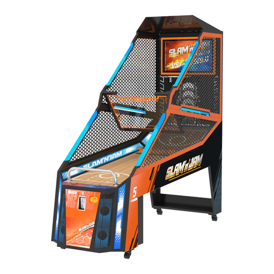
Page 7: Introduction
INTRODUCTION Congratulations on your purchase of Slam ‘n’ Jam by LAI Games. We hope you take the time to read this manual and learn about the many features and user-friendly adjustments that can be made to fine-tune the game for maximum earning potential. -
Page 8: Location Requirements
LOCATION REQUIREMENTS • Ambient temperature: 5C - 40C • Ambient humidity: • Ambient U.V. radiation: Very low • Vibrations level: BILL VALIDATOR REQUIREMENTS • Volts: 12VDC • Magazine Size: Up to 1000 bill capacity DIMENSIONS • Weight: 400kg (882 lb.) (with packaging) •... -
Page 9: Contents Detailed
CONTENTS DETAILED... -
Page 10: Unpackaging
UNPACKAGING WARNING: The use of three persons is required to unpack the machine. Take caution when removing heavy parts, and when removing the unit from the pallet. 1. After removing the box and packaging, remove the screws that affix the basketball backboard. Remove 8 screws first, and reserve one screw at the top of the left and right sides to prevent the backboard from falling. - Page 11 2. Remove the items inside the cover (such as basketballs, hoop, support box, etc.). Remove the top screws and then remove the connecting fixed bracket at the bottom of the cover. 3. Remove the screw at the top of each fence, then remove the 3 fixing screws at the bottom. The fences can now be taken out and set aside.
- Page 12 4. First remove the screws of the top bracket while a second person holds the fence. Once the top bracket is removed, lift and remove the fence and set aside. Then remove the bottom fixed bracket. 5. Remove 4x M6 screws from both sides of the fuselage, remove the ball shield, then remove the screws of the fixing bracket and remove the bracket.
- Page 13 6. Using two people, remove the 6x M6 screws from both sides of the electrical box, then remove the electrical box and set aside. 7. Remove the 4x Phillips screws fixed on the side of the console, take out the console together with the fixed brackets, and then remove the brackets from the console.
-
Page 14: Assembly
ASSEMBLY WARNING: The use of two persons is required to assemble the machine. Take caution when lifting and installing heavy items. CAUTION: Lock all four wheels once the cabinet is down in its final position to avoid movement during installation. NOTE: Due to excessive vibration on basketball games, we advise the use of the provided liquid thread-locker when installing hardware. - Page 15 2. Secure the hoop with 5x M5*20 screws. Washers and lock washers are required. 3. Place the lower right fence on the right side of the playfield, install 7x M6*45 screws with spring washers and washers. Once the fence is installed, install the ball guide bracket with 3x M4*12 screws.
- Page 16 4. Set the upper-right fence on top of the lower-right fence, install 3x M6*45 screws from the top of the lower fence to secure. Pass any LED wiring from the top and bottom of the upper fence through the backboard openings. Use 5x M6*45 screws from the back to connect the backboard to the upper fence.
- Page 17 5. Place the lower-left fence on the left side of the playfield. Secure with M6*45 screws, spring washers and washers. Once the fence is installed, install the ball guide bracket with 3x M4*12 screws.
- Page 18 6. Place the upper-left fence on top of the lower-left fence, install 3 M6*45 screws from the top of the lower fence secure. Once installed, use 5x M6*45 screws to secure the fence to the backboard.
- Page 19 7. Place the top cover on top of the upper fences. Connect the top cover to the fence with the connection brackets. Secure with 12x M6*12 screws. 8. The ball shield will be assembled between the two upper fences. The LED connection is on the right side of the machine.
- Page 20 9. Slide the player console into the front opening of the machine. Open the front maintenance door and secure the console with 4x M6*12 screws. 10. Install the electrical box behind the player console, under the playfield. Secure with 6x M6*12 screws.
-
Page 21: Power And Data Connections
POWER AND DATA CONNECTIONS 11. Remove the small triangular cover on the front of the lower-left fence, connect the wires and replace the triangular cover. 12. Remove the small triangular cover on the front of the lower-right fence, connect the wires and replace the triangular cover. - Page 22 13. Remove the covers on the back of the backboard and connect the power and DVI cables to the monitor. 14. Connect the wiring for the left fence LEDs.
- Page 23 15. Connect the wiring for the right fence LEDs. Reinstall the monitor and cable cover. 16. Open the rear access door of the electrical box and connect all wiring shown below.
- Page 24 17. Remove the ball shield connection cover and connect the wires for the LED. Replace the cover.
-
Page 25: Gameplay And Modes
GAMEPLAY AND MODES OBJECTIVE Players compete against each other and the clock to advance through rounds to earn tickets. HOW TO PLAY • Insert credit. • Select VS or Solo mode. • Receive combo points for baskets made in quick succession. •... -
Page 26: Basic Settings
BASIC SETTINGS 1. Free play – Allows the game to be played without credits (Adjustable ON/OFF, Default OFF) 2. Machine ID – Allows for multiple cabinets to be linked. Change this setting on each cabinet to use VS mode (Adjustable 1P-8P, Default 1P). 3. -
Page 27: Game Parameters
GAME PARAMETERS Activate this hidden menu from the Basic Setting menu. Once activated, select “Save and exit” from the Basic Setting menu, then exit the main menu to return to regular gameplay mode. Re-enter the main menu to find Game Parameters as a main menu option. Use this menu to set the duration and points goals of each round. -
Page 28: Suggested Settings
SUGGESTED SETTINGS Customize settings to lower game time, raise/lower payout, and set achievable goals for clientele based on their skill level. Some suggested settings are below. Basic Setting SETTING 1: SETTING 2: LESS SKILLED MORE SKILLED PLAYERS PLAYERS Game music Standby music Loop music 2MIN... -
Page 29: Monitor Test
MONITOR TEST Perform this test to check the monitor image. The screen should appear as shown below. LINKING CABINETS Up to 8 cabinets can be linked via routers. One router is provided per 4 machines. See router hook up instructions for two machines below (note: router models differ). Once the router is powered on and all Cat5e cables are installed. -
Page 30: Errors And Troubleshooting
ERRORS AND TROUBLESHOOTING The following errors can occur during normal operation. The display will update when the error occurs and automatically clear when the fault condition is removed. No. Name Possible Cause Solution • • Ball gate Cycle power on the machine Ball gate limit sensor has •... - Page 31 • • Ticket Game is out of tickets. Fill tickets. • • dispenser Switch position is not Adjust switch as shown below. • error correct on the ticket Check connections. • dispenser. Verify 12VDC is present (lights on • Loose connection. mechanism) •...
- Page 32 • • Hoop Sensor out of alignment. Check if either sensor is loose. • • sensor Reflective sticker on front of Check sticker condition. • error hoop is missing or worn. Check connections. • • Loose connection on sensor. Check 12VDC is present (lights on sensor). •...
-
Page 33: Common Service Areas
COMMON SERVICE AREAS WARNING: Be sure to read the following carefully and obey all warnings before servicing the machine CABINET FRONT 1. Bill acceptor cover 2. Card reader cover 3. Console front door 4. Coin acceptor 5. Control panel 6. Ticket dispenser 7. -
Page 34: Technical Service Areas
TECHNICAL SERVICE AREAS NOTE: Be sure to read the following carefully before servicing the machine WARNING: It is advised that anyone using this section for repairing or modifying any of the components of the game should be a qualified technician, having at least a basic knowledge of digital components, integrated circuits and electricity. -
Page 35: Android Pcb
ANDROID PCB 1. Power connection 2. Audio connection 3. HDMI to monitor 4. USB (used for software updates) 5. Cabinet linking connection 6. I/O PCB connection I/O BOARD OUTPUT INPUT INPUT INPUT OUTPUT IN1 Ball gate upper limit sensor IN11 Ticket signal OUT1 Ball gate motor... -
Page 36: Mains Switch/Fuse Pcb
MAINS SWITCH/FUSE PCB The power inlet is a standard IEC inlet socket with a mains power switch, located at the rear of the electrical box. There is a main power fuse internal in this IEC socket. Use the steps below when replacing fuses. -
Page 37: Preventative Maintenance
PREVENTATIVE MAINTENANCE EXTERIOR • Regularly dust and clean the external cabinet areas as required, using a soft water-damp cloth and mild soap. • Check for blown bulbs and replace as required. Check all LED strips are functioning, and repair as required. •... -
Page 45: Mechanical Illustrations
MECHANICAL ILLUSTRATIONS PLAYFIELD ASSEMBLY NO. PART# Name Quantity 050650033 Machine body 040650009 Front wooden board 190650029 Right middle LED acrylic 050650047 Right LED bottom cover C 1 050650071 Bottom cable slot 040650010 Back wooden board 190650027 Right front LED acrylic 050650044 Front LED box 050650045 Right LED bottom cover 050650046 Right LED bottom cover B 1... -
Page 46: Player Console Assembly 2
PLAYER CONSOLE ASSEMBLY PART# Name Quantity 090110002 Ticket dispenser 050650034 Console 050650036 Coin box shell 050650037 Coin box inner box 230140009 SXW- short lock 240320002 Handle 050650039 Control box 050650072 Right speaker box 090150001 Coin mech 190650024 Right speaker acrylic 2 090020016 4.5 inch speaker 190650022 Console board 050650031 Card reader cover... -
Page 47: Ball Gate Assembly
BALL GATE ASSEMBLY Name Quantity 050650050 The holder of the ball gate 050650137 Motor spindle 240300001 Sliding block 060650001 Sliding spindle 050650051 Ball gate base and cover 190650026 Ball gate acrylic board 050650130 Ball gate acrylic board cover 090050043 Ball gate motor 050650129 Spindle cover B 060650003... - Page 48 BALL SHIELD & TOP COVER ASSEMBLY NO. PART# Name Quantity NO. PART# Name Quantity 050650018 Ball shield mould plate 050650016 Roof sheet metal 050650017 Ball shield holder 050650061 Roof connecting plate 1 190650025 Ball shield acrylic board 1...
- Page 49 LEFT & RIGHT UPPER FENCE ASSEMBLY NO. PART# Name – LEFT ASSEMBLY Quantity NO. PART# Name – RIGHT ASSEMBLY Quantity 050650015 Upper left sheet metal component 050650013 Upper right sheet metal component 050650014 Upper left orange sheet metal 050650012 Upper right orange sheet metal 050650079 Upper left orange sheet metal B 050650060 Upper right orange sheet metal B 190650036 Side front luminous acrylic...
- Page 50 LEFT & RIGHT LOWER FENCE ASSEMBLY NO. PART# Name – RIGHT ASSEMBLY Quantity NO. PART# Name – LEFT ASSEMBLY Quantity 050650009 Lower right group welding 050650011 Lower left group welding 190650036 Side front luminous acrylic 1 050650010 Orange plug-in left 050650008 Orange plug-in right 050650078 Orange plug-in left B 050650059 Orange plug-in right B...
- Page 51 ELECTRICAL BOX ASSEMBLY NO. PART# Name – LEFT ASSEMBLY Quantity 050650043 Electrical box 040650011 Electrical box back board 050650054 Electrical box cover board 050650056 Cable box sheet metal 050650055 Power plug box 050650057 Electrical box repair door 090160021 Digital power amplifier PCB 070010011 PCB 080650002 I/O PCB FS-P6616 070160001 Solid state relay...
-
Page 52: Backboard Assembly
BACKBOARD ASSEMBLY NO. PART# Name Quantity NO. PART# Name 050650080 Hoop 240320002 Handle 190650033 Front acrylic board of the screen 1 050650132 Backboard cables slot 050650066 Hoop bracket 050650133 Backboard cables slot cover 040650013 Wooden backboard 090070002 Goal sensor 050650063 Wooden backboard frame 050650081 Goal sensor bracket 170040046 Cables slot 190650035 Left and right acrylic... - Page 53 LAI Games shall have no liability related to such improper and unauthorized use and/or operation of the hardware and licensed software, and Operator shall indemnify, defend, and hold LAI Games harmless for any claim or cause of action brought against LAI Games arising from Operator’s or Operator’s representative’s improper and unauthorized use and/or operation of the hardware and licensed software.
- Page 54 WARRANTY LAI Games warrants its manufactured products for a period of 3 months inclusive of parts and labor from the date of sale. LAI Games exclusive obligation is to repair any item with any defects as a result of faulty workmanship or materials, providing the defective item or items of equipment are returned to the LAI Games distributor from which the machine was purchased.
Need help?
Do you have a question about the SLAM N JAM and is the answer not in the manual?
Questions and answers