
Related Manuals for Max RB397


Summary of Contents for Max RB397
- Page 1 CONFIDENTIAL SERVICE MANUAL RE-BAR TYING TOOL RB397 (CE) Model Specifications and parts may be changed for improvement.
- Page 2 CONFIDENTIAL SERVICE MANUAL RE-BAR TYING TOOL RB397 (CE) Model Specifications and parts may be changed for improvement.
-
Page 3: Specifications And Technical Data
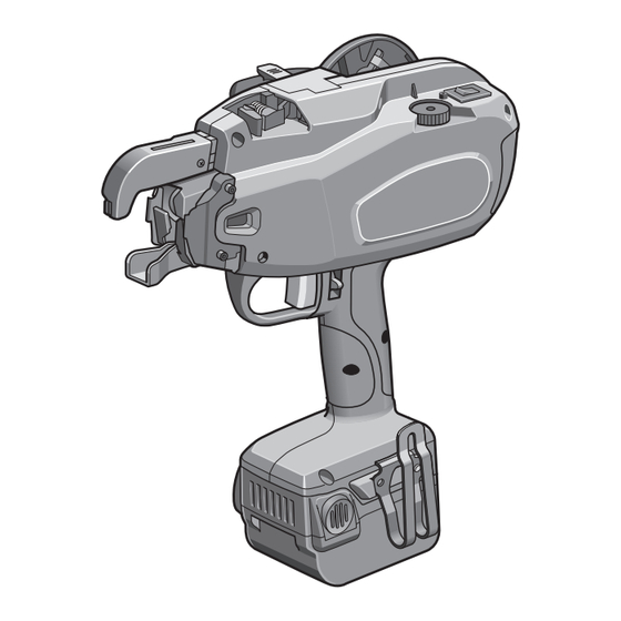
1. SPECIFICATIONS AND TECHNICAL DATA 1. NAME OF PARTS 2. TOOL SPECIFICATIONS PRODUCT NO. RB397 <Battery charger> Product name MAX lithium ion battery WEIGHT 2.4 kg (Battery included) charger HEIGHT 305 mm (12") Product code JC928 (CE) WIDTH 105 mm (4-1/8") -
Page 4: Wire Specifications
TIES PER COIL RB397 Approx. 120 ties/coil TIES PER CHARGE Approx. 1400 ties/charge BATTERY CHARGER: Use only an authorized Battery charger, MAX JC928. 4. TECHNICAL DATA (1) NOISE A-weighted single-event ------ LWA, 1s, d 86 dB sound power level A-weighted single event ------ LpA, 1s, d 76 dB... - Page 5 6. APPLICABLE BAR SIZES Minimum Maximum D10 D10 (#3 #3) D16 D19 (#5 #6) RB397 7. ABOUT PRODUCTION YEAR This product bears production number in the body. The two digits of the number from left indicates the production year.
- Page 6 2. REQUIRED TOOLS AND ADHESIVE Technical Tool/Adhesive/Grease Size Where to Use Illustration No. For bolt M3 Width across flats 2.5 mm Hexagonal wrench key For bolt M4 90 175 Width across flats 3 mm For bolt M4 Assembling partition unit Width across flats 5.5 mm Assembling release stopper Socket wrench...
- Page 7 No image Those covering by 5 to 200 cN・m (10) (11) (12) See page 56. 5...
- Page 8 3. PROCESS DESIGN ORDER FOR ASSEMBLY 1. Tip Axis Assy. (1) Assembling the Tip Axis B Unit/Sleeve A/Guide Apply MOLYKOTE YM-103. TIP AXIS A (RB12018) KEY B (2 Places) (RB10026) TIP AXIS B UNIT (RB70377) COMPRESSION SPRING 3730 (KK23730) KEY (2 Places) (RB12014) Beware of the direction of a Apply MOLYKOTE YM-103 projection.
- Page 9 2. Tip Axis Assy. (2) Assembling the Cutter Ring Assy. Apply MOLYKOTE YM-103. (Fully apply Apply MOLYKOTE YM-103. CUTTER RING UNIT to the entire surface of a groove) (RB70412) Beware of the assembly direction. C-RING 14 (JJ21407) Align the projection of the Cutter Ring Guide with the recess CUTTER RING GUIDE of the Cutter Ring Unit.
- Page 10 3. Tip Axis Assy. (3) Assembling the Hook Move the Tip Axis B unit forward to the Hook opening position. Turn the Tip Axis B unit to align its groove with a groove in the Sleeve A. Hook Assembly Align the holes in the Hook Position with that in the Sleeve A.
- Page 11 4. Tip Axis Assy. (4) Assembling the Spring Collar, Compression Spring and Tip Axis Guide Assy. SPRING COLLAR (RB12020) (2 PIECE) BUMPER (RB12019) COMPRESSION SPRING 9026 (KK29026) Apply MOLYKOTE Apply MOLYKOTE YM-103 to the entire surface. YM-103 to the entire surface. C-Ring 20 Assembly Direction Round Side Edged Side...
- Page 12 5. Tip Axis Assy. (5) Assembling the Wheel to the Internal Gear Balls Invisible Side Front and Back of Wheel 6704 Balls Invisible Side Balls Visible Side ASSEMBLY PROCEDURE 1. Check the front and back of the Wheel to assemble it to the Internal Gear. There is resistance when assembling.
- Page 13 6. Tip Axis Assy. (6) Assembling the Internal Gear and Planet Gauge Unit INTERNAL GEAR (RB10338) PARALLEL PIN 1589 (FF31589) PLANET CAGE UNIT (RB70408) Needs Anti-Electrostatic Countermeasure Check that the spring and spring collar do not move in the axial direction when moving the tip axis. If the keys are properly assembled, they do not move.
- Page 14 7. Arm Assy. (397) (RB70402) (1) Assembling the Arm B Unit and Wire Guide B BOLT 3 x 5 CF (BB40711) ARM B UNIT (397) (RB70404) Dowels of Arm B Unit WIRE GUIDE B (397) Degrease (RB11999) ASSEMBLY PROCEDURE 1. Degrease the Wire Guide B (397). (Female threads, 2 places) 2.
- Page 15 8. Arm Assy. (397) (RB70402) (2) Adhering the Plate ARM A UNIT (After) (RB81175) Degrease the female threads. PLATE (RB12085) Degrease ARM A UNIT (397) (RB70403) Ensure that the Plate does not project from the Arm A. See Detail A Plate Adhering Area.
- Page 16 9. Arm Assy. (397) (RB70402) (3) Assembling the Cutter Lever A Apply MOLYKOTE CUTTER LEVER A (397) (RB12005) YM-103. HOLLOW PIN 1686 (FF51686) Beware of the assembly SHAFT (RB11846) direction of the Cutter Lever A. ASSEMBLY PROCEDURE 1. Apply MOLYKOTE YM-103 to a hole in the Cutter Lever A (397). 2.
-
Page 17: Connecting Rod
10. Arm Assy. (397) (RB70402) (4) Assembling the Connecting Rod Pass the Connecting Rod (397) between the Arms C and A. Beware of the assembly direction of the Connecting Rod (397). CONNECTING ROD (397) (RB12004) E-RING 3 CF (JJ10514) CUTTER LEVER A Apply MOLYKOTE... - Page 18 11. Arm Assy. (397) (RB70402) (5) Assembling the Cutter Lever B CUTTER LEVER PIN SHAFT Beware of the assembly direction of the Cutter Lever B. E-RING 2 (JJ10109) CUTTER LEVER B (397) (RB12090) ASSEMBLY PROCEDURE 1. Set the Cutter Lever B (397) onto the Shaft and Cutter Lever Pin. Beware of the assembly direction of the Cutter Lever B (397).
- Page 19 13. Arm Assy. (397) (RB70402) (7) Assembling the Cutters CUTTER PLATE UNIT FIXED CUTTER (RB12001) CUTTER (RB12000) Apply MOLYKOTE Larger Hole-Diameter ARM A YM-103. Side (Round Hole Side) Cutter Assembly Direction Smaller Hole- Larger Hole- Diameter Side Diameter Side (Long Hole Side) (Round Hole Side) See Detail A...
- Page 20 14. Arm Assy. (397) (RB70402) (8) Assembling the Wire Guide A WIRE GUIDE A (397) (RB11998) ARM A Dowels (2 Places) ASSEMBLY PROCEDURE 1. Assemble the Wire Guide A (397) to the Arm A. Align holes in the Wire Guide A (397) with the dowels of the Arm A to position. 18...
- Page 21 15. Arm Assy. (397) (RB70402) (9) Assembling the Arm B Assy. ARM JOINT SCREW WIRE GUIDE A PARALLEL PIN (SHORT) ARM B ASSY. Assy. Assembled in Arm Assy. (1) BOLT 3 x 6 (BB40112) Rotate the Cutter Lever A to check that the Cutter rotates smoothly. Should fully swing by empty weight.
- Page 22 16. Arm Assy. (397) (RB70402) (10) Assembling the Leaf Spring Visual Check Visual Check LEAF SPRING (397) (RB11997) Tilting the Leaf Spring, put in between the Arm A Unit. Turn the Leaf Spring in the arrow direction to fit a hole in the Leaf Spring onto the dowel After degreasing, apply ThreeBond PAN-HEAD SCREW...
- Page 23 17. Feeding Assy. (RB81137) (1) Assembling the Feeding Gear A Unit Apply MOLYKOTE Greasing Area of YM-103. Feeding Gear A Unit Apply MOLYKOTE YM-103. FEEDING GEAR Apply A UNIT MOLYKOTE YM-103. (RB70509) FEEDING GEAR SHAFT Greasing Area of Feeding Gear Shaft FEEDING MOTOR ASSY.
- Page 24 18. Feeding Assy. (RB81137) (2) Assembling the Partition Unit PARTITION UNIT (RB70434) HEX, NUT 1-3 (CC41104) PARTITION SPONGE (RB12045) Degrease Apply an adhesive agent LOCTITE 242. SPONGE Ensure that the Partition Sponge is projecting SUPPORT from the edges of the Partition Unit. (RB12044) INTERMEDIATE SCREWS...
- Page 25 19. Feeding Assy. (RB81137) (3) Assembling the Feeding Gear B1 Unit E-RING 2.5 (JJ10113) PLANE WASHER 2-3 (EE32104) FEEDING GEAR B1 UNIT (RB10357) FEEDING GEAR SHAFT Needs Anti-Electrostatic Countermeasure ASSEMBLY PROCEDURE 1. Fit the projection of the Feeding Gear B1 Unit into a groove in the Feeding Gear A Assy. 2.
-
Page 26: Release Lever
Anti- Electrostatic Part 20. Release lever Assy. (RB81138) Assembly Direction of Feeding Gear B2 Unit Hold the fully grooved side in the direction shown in the figure and assemble it. E-RING 2.5 (JJ10113) Fully Grooved Side FEEDING GEAR B2 UNIT (RB10359) RELEASE LEVER (RB10362) STEP PIN 1809... - Page 27 21. Ratchet Cover Assy. PARALLEL PIN 1563 (FF31563) RATCHET COVER (RB12037) Bring an inwardly bent leg into contact with the Ratchet Cover. RATCHET UNIT (RB70432) TORSION SPRING 4089 (KK34089) Bring the other leg into contact with the Ratchet Unit. Correct Assembly Incorrect Assembly ASSEMBLY PROCEDURE 1.
- Page 28 22. Jaw Base Assy. (RB70495) Hook a longer arm onto the lower part of the Jaw A. JAW A (RB10368) STEP PIN 1822 TORSION SPRING 3249 (FF41822) (KK33249) JAW BASE (RB10370) Hook a longer arm onto the lower part of the Jaw B. E-RING 2.5 (JJ10113) JAW B (RB10369)
- Page 29 23. Pipe Assy. (RB81136) E-RING 4 (JJ10101) PIPE (RB12006) PIPE SPONGE (RB12007) ASSEMBLY PROCEDURE 1. Fit the Pipe Sponge onto the Pipe. (As far as the root of the tapered inlet section of the pipe) 2. Fit the E-Ring 4 into the groove in the Pipe (2 places). Check that the E-Ring has been properly fit into the groove.
- Page 30 25. Reel Guide Assy. (RB81141) (1) Press-fit the Hollow Pin to the Reel Guide REEL GUIDE (RB11988) Press-fit the Hollow Pins as far as this plane of the Reel Guide. HOLLOW PIN 1652 (FF51652) See Detail A Detail A Cross-Section A-A Scale 2:1 ASSEMBLY PROCEDURE 1.
- Page 31 27. Reel Stay Assy. (RB70426) (2) Assembling the Reel Stopper Assy. Reel Stay Boss of Reel Stay REEL STOPPER ASSY. (RB70427) PLANE WASHER 3.1 x 12 x 0.8 (EE39907) SCREW M3 x 6 CF (AA31721) ASSEMBLY PROCEDURE 1. Fit the Reel Stopper Assy. onto the boss of the Reel Stay. 2.
- Page 32 28. Reel Stay Assy. (RB70426) (3) Assembling the Reel Stopper Spring Reel Stay Reel Stopper Spring Mounting Area Turn the Reel Stopper and make sure that REEL STOPPER it can lock and release at “LOCK” and “RELEASE” respectively. REEL STOPPER SPRING (RB12038) SCREW M3 x 6 CF...
-
Page 33: Led Cover
29. Reel Stay Assy. (RB70426) (5) Assembling the LED Cover Needs Anti-Electrostatic Countermeasure After degreasing, apply ThreeBond LED COVER 1401B. (RB12039) SCREW M3 x 6 CF (AA31721) ASSEMBLY PROCEDURE 1. Degrease the Screw M3 x 6 CF. 2. Fit the LED Cover onto the LED cover mounting area of the reel stay. 3. - Page 34 30. Release Stopper Assy. (RB81139) STEP PIN (RB12054) Degrease RELEASE STOPPER (RB12053) ThreeBond 1401B Should turn smoothly. HEX, NUT 1-3 STOPPER BASE (Punched Surface Downward) (RB12055) Degrease SPONGE F (RB12056) ASSEMBLY PROCEDURE 1. Degrease the Step Pin. 2. Put the Step Pin through the Release Stopper and Stopper Base. 3.
- Page 35 31. Brake Assy. (RB70494) (1) Assembling the Rotary Plate and Rotary Shaft ROTARY SHAFT (RB12026) Beware of the assembly Beware of the direction of direction of the Rotary the D-shaped section. Plate and Rotary Shaft (D-shaped section). ROTARY PLATE (RB12029) SPRING PIN 2 x 12 (FF21620) Ensure that the Spring Pin is...
- Page 36 33. Brake Assy. (RB70494) (3) Assembling the Rotary Plate and Brake Link Apply MOLYKOTE YM-103 STEP PIN 1855 (FF41855) (entire circumference). ROTARY PLATE BRAKE LINK E-RING 2.5 (JJ10113) Handle the Iron Assembly Direction of Brake Link Core with Care At the time of assembly, ensure that the hatched area of the solenoid’s iron core is free from any oil adhesion and flaw.
- Page 37 1. Fit the Rotary Shaft into a hole in the Plate C. 2. Fit the Brake Link into a slit in the Brake Base. 3. Fit the iron core into the frame of the Solenoid Unit (RB397). Beware of the direction of the frame at the time of assembly.
- Page 38 35. Frame L Unit (RB70399) (1) Apply quick drying adhesive (2 Places). Apply quick drying adhesive (circumference). HEX, NUT 1A M4 CF PLATE A (RB11978) (CC42512) Degrease Degrease FRAME L (RB11977) Apply quick drying adhesive Apply quick drying adhesive (2 Places). (2 Places).
-
Page 39: Warning Label
36. Frame L Unit (RB70399) (2) Apply quick drying adhesive (2 Places). HEX, NUT 1-3 (CC41104) Degrease HOLLOW PIN 2111 (FF52111) Apply quick drying adhesive (2 Places). HEX, NUT 1A M4 CF (CC42512) Degrease ASSEMBLY PROCEDURE 1. Apply quick drying adhesive to two outer circumferential spots of the degreased Hex Nut 1-3 and press-fit it into the Frame L. - Page 40 38. Frame L Assy. Assembling the Cover L COVER L (397) (RB11979) BOLT 3 x 8 CF (BB41503) Drawing after Assembly FRAME L ASSY. (397) (RB70500) BOLT 3 x 8 CF (BB41503) ASSEMBLY PROCEDURE 1. Set the Cover L onto the Frame L Assy. (397). 2.
- Page 41 39. Frame R Unit (RB70505) Apply quick drying adhesive (2 Places). FRAME R (RB11980) HEX, NUT 1-3 (CC41104) Degrease HOLLOW PIN 2111 Apply quick drying adhesive (2 Places). (FF52111) HEX, NUT 1A M4 CF (CC42512) Degrease ASSEMBLY PROCEDURE 1. Apply quick drying adhesive to two outer circumferential spots of the degreased Hex Nut 1-3 and press-fit it into the Frame R.
- Page 42 LABEL, MAIN SWITCH (RB11982) 397 LABEL (RB397CE) LABEL, CURL GUIDE (RB11984) (RB11983) (397 Label (RB397 USA) for USA) (RB12127) ASSEMBLY PROCEDURE 1. Degrease each label pasting area of the Frame R. 2. Paste the 397 Label (RB397CE) to the Frame R.
- Page 43 (RB11981) BOLT 3 x 8 CF (BB41503) FRAME R ASSY. (397CE) (RB70400) (397 Frame R Assy. (RB397 USA) for USA) (RB70475) ASSEMBLY PROCEDURE 1. Set the Cover R onto the Frame R Assy. 2. Tighten the Bolts 3 x 8 CF. (Tightening torque: 100 to 150 cNm (8.9 to 13.3 lbfin))
- Page 44 42. Motor Cover Assy. (RB70401) Pasting the Warning Label MOTOR COVER (RB11986) Missing of the Warning Label is hazardous because the user is not properly warned about danger. Degrease with alcohol. WARNING LABEL A (CE) (RB12100) (Warning Label A (USA) for USA) (RB10421) ASSEMBLY PROCEDURE 1.
- Page 45 43. Frame L Assy. (2) Assembling the Nut Plate NUT PLATE (RB11687) SCREW M3 x 6 CF (AA31721) Degrease ASSEMBLY PROCEDURE 1. Degrease the Nut Plate. 2. Fix the Nut Plate to the Frame L Assy. with the Screw M3 x 6 CF. (Tightening torque: 28 ±...
- Page 46 Anti- Electrostatic Part 44. Frame L Assy. (3) Assembling the Relay Board Unit Needs Anti-Electrostatic Countermeasure SCREW M3 x 6 CF (AA31721) RELAY BOARD UNIT (RB70461) SCREW M3 x 6 CF (AA31721) RELAY BOARD HARNESS UNIT (RB70465) ASSEMBLY PROCEDURE 1. Fit the Relay Board Harness Unit into the Relay Board Unit. * Beware of the connecting direction.
- Page 47 45. Frame L Assy. (4) Assembling the Sensor Board D Unit Needs Anti-Electrostatic Countermeasure SENSOR BOARD D UNIT (RB70459) Degrease Apply ThreeBond 1401B. SCREW M2 2 x 8 (AA31724) Do not position on the wall at 2 places. ASSEMBLY PROCEDURE 1.
- Page 48 46. Frame L Assy. (5) Temporarily Assembling the Solenoid Brake BRAKE ASSY. (RB70494) ASSEMBLY PROCEDURE 1. Check that the harness connection of the Brake Assy. is positioned and directed as shown in the figure. 2. Fit the Rotary Shaft into a hole in the Plate A and set the Brake Base by putting the dowel of the Frame L into a hole in the Brake Base.
- Page 49 47. Frame L Assy. (6) Assembling the Jaw Base Assy. BOLT 3 x 8 CF (BB40710) PLANE WASHER 2-3 (EE32104) JAW BASE ASSY. (RB70495) Identify: Without Earth Wire: Acceptable Without Earth Wire: Unacceptable --- for other models ASSEMBLY PROCEDURE 1. Check the jaw height of the Jaw Base Assy. and the assembled condition of the E-Ring. 2.
- Page 50 48. Frame L Assy. (7) Assembling the Reel Guide Assy. REEL GUIDE PLATE (RB11989) Needs Anti-Electrostatic Countermeasure REEL GUIDE ASSY. (RB81141) PAN-HEAD SCREW 3 x 8 CF (AA21419) Assembly Direction of Reel Guide Assy. and Reel Guide Plate Align the stepped figure of the Reel Guide Assy.
- Page 51 49. Frame L Assy. (8) Assembling the Ratchet Assy. Needs Anti-Electrostatic Countermeasure RATCHET COVER ASSY. (RB70429) BOLT 4 x 10 CF (BB41708) ASSEMBLY PROCEDURE 1. Fix the Ratchet Cover Assy. to the Frame L with the Bolts 4 x 10 CF (2 pieces). (Tightening torque: 100 to 150 cNm (8.9 to 13.3 lbfin)) TORQUE ADHESIVE...
- Page 52 50. Frame L Assy. (9) Assembling the Reel Press HOLLOW PIN 2113 (FF52113) TORSIN SPRING 3373 (KK33373) Shorter Longer REEL PRESS PLATE B (RB12025) (RB12099) Hook the longer leg of the Torsion Spring 3373 onto the Reel Press. ASSEMBLY PROCEDURE 1.
- Page 53 51. Frame L Assy. (10) Assembling the Feeding Assy. FEEDING ASSY. (RB81137) Assembly Position of Feeding Assy. Align the Partition with Route the Sensor B Harness the Frame L. behind the Motor so that it will not be caught between the Motor Cover and the Frame.
- Page 54 Frame L Assy. (11.1) Assembling the Motor Cover, Reel Holder and Reel Stay – 1 Assembly Position of Reel Stay Assy. Fit the Plate B into the recess of the Reel Stay. Assembly Position of Harness Reel Stay Assy. Wiring Connection Pass through the Pass between the recess of the Reel Stay.
- Page 55 53. Frame L Assy. (11.2) Assembling the Motor Cover, Reel Holder and Reel Stay – 2 TORSION SPRING 4067 STEP PIN 1821 (KK34067) (FF41821) Reel Holder Assy. MOTOR COVER ASSY. (397CE) (RB70401) (Motor Cover Assy. (397 USA) for USA) PLANE RUBBER WASHER 1.8 x 6 x 2 (RB70476) (EE39609)
- Page 56 54. Frame L Assy. (12) Assembling the Joint JOINT (RB12031) Close the Reel Holder and set the Release Stopper to “CLOSE”. BOLT 3 x 50 CF Ensure that a (BB40515) projecting part is positioned on the BOLT 3 x 10 Reel Stay side.
- Page 57 55. Frame L Assy. (13) Adjusting the Position of the Brake Assy. BOLT 4 x 8 CF (BB40712) ASSEMBLY PROCEDURE 1. Fix the Brake Assy. to the Frame with the Bolt 4 x 8 CF. (Tightening torque: 125 ± 25 cNm (11 ± 2.2 lbfin)) TORQUE ADHESIVE 125 ±...
- Page 58 56. Frame L Assy. (14.1) Adjusting the Reel Holder Head Note for Note for Adjustment – 2 Adjustment – 1 “23.95” jig “23.25” jig Align a groove in a jig with Set the Release the falling direction by the Stopper to “CLOSE”. empty weight of the jig.
- Page 59 57. Frame L Assy. (14.2) Adjusting the Reel Holder Head * If the Reel Holder passes the previous procedure (14.1 (previous page)), no need to do this procedure. Check that the Check that the “23.95” jig does not “23.25” jig falls by Note for Adjustment –...
- Page 60 58. Frame L Assy. (16.1) Assembling the Arm Assy. – 1 PIPE ASSY. (RB81136) ARM ASSY. (RB70402) ASSEMBLY PROCEDURE 1. With the Pipe Assy. fit into the Arm Assy., assemble the Arm Assy. to the Frame. 58...
- Page 61 59. Frame L Assy. (16.2) Assembling the Arm Assy. – 2 SCREW (RB12003) TORSION SPRING 3370 (KK33370) Unacceptable: Gap between the Frame and the Sponge Acceptable: No gap between the Frame and the Sponge ASSEMBLY PROCEDURE 1. Fix the Arm Assy. to the Frame L Assy. with the Screw. (Tightening torque: 150 to 200 cNm (13.3 to 18 lbfin)) 2.
- Page 62 60. Frame L Assy. (17) Assembling the Switch Lever Unit HOLLOW PIN 2111 (FF52111) SWITCH LEVER UNIT (RB70473) Shorter Spring Leg TORSION SPRING 4083 (KK34083) Hook onto the rib of the Frame. Longer Spring Leg SWITCH LEVER PIN (RB11686) Hook onto the projection of the Switch Lever.
- Page 63 61. Frame L Assy. (18) Assembling the Curl Guide Assy. CURL GUIDE ASSY. (397) (RB70405) Assembly Position of Curl Guide Assy. BOLT 3 x 16 CF Ensure that the end of tip of the (BB40709) Torsion Spring comes into contact with the rib of the Frame.
- Page 64 62. Frame L Assy. (19.1) Wiring the Main Circuit Board, Main Switch Base and Electrode MAIN CIRCUIT BOARD UNIT (RB397) (RB70446) (5) Connect the Interface Harness. Needs Anti-Electrostatic INTERFACE Countermeasure HARNESS UNIT (RB397) (RB70454) TRIGGER SWITCH UNIT (RB397 White/Green) (RB70453)
- Page 65 ASSEMBLY PROCEDURE 1. Check the following two points with the label pasted onto the back of the Main Circuit Board Unit. (1) Program version --- The 3 right digits indicates the latest version, as shown in Fig. 1. 2. Pass the connector of the Trigger Unit through a passage in the center of the board case to connect it to the CN1 of the Main Circuit Board.
- Page 66 Wiring the Main Circuit Board, Main Switch Base and Electrode – 2.1 MAIN SWITCH BASE ASSY. (RB81140) (2) Temporarily set the Main Switch Base. MAIN CIRCUIT BOARD UNIT (RB397) (RB70446) (4) Pass the harness directly mounted to the main switch through a passage.
- Page 67 Photo 1: Tab Terminal Connecting Position Check good good Male Terminal Plugged Male Terminal Plugged in between into Female One Female One and Sleeve Photo 2: Connector Plugging Depth Within 18 mm (3/4”) ASSEMBLY PROCEDURE 1. Connect the Relay Board Harness Unit coming from the relay board to the CN10 of the Main Circuit Board Unit.
-
Page 68: Main Circuit Board Unit
64. Frame L Assy. (19.2.2) Wiring the Main Circuit Board, Main Switch Base and Electrode – 2.2 MAIN SWITCH BASE ASSY. (4) Connect the Connector of the Solenoid. (3) Fix the Main Switch Base. MAIN CIRCUIT BOARD UNIT Photo 1 (1) Connect the Connector of the Ratchet (White/Black). - Page 69 ASSEMBLY PROCEDURE 1. Connect the Sensor Board E Harness Unit coming from the Ratchet to the CN4 of the Sub-circuit Board. * Beware of the connecting direction. (white harness to “1 (white)” of the CN4.) * Ensure that the Harness does not come into contact with the Rotary Plate and Dial Spring. 2.
- Page 70 65. Frame L Assy. (19.3) Wiring the Main Circuit Board, Main Switch Base and Electrode – 3 SENSOR CIRCUIT BOARD D UNIT (RB70459) (6) Fit the Trigger Unit into the Frame. (1) Connect the Harness (Gray/Gray/White) of the Sensor Circuit Board D Unit. (4) Pass the Power Harness (Black) through 3 (5) Fit the Electrode Unit into bosses to connect it to the Electrode Board.
- Page 71 ASSEMBLY PROCEDURE 1. Connect the Harness of the Sensor Circuit Board D Unit to the CN7 of the Main Circuit Board. * Beware of the connecting direction. (white harness to “1” of the CN7.) 2. Fit the Battery Signal Harness Unit Into the 3 right bosses within the grip and connect it to the CN5 of the Electrode Unit.
-
Page 72: Planet Gear
66. Frame L Assy. (21) Assembling the Sun Gear Unit and Tip Axis Assy. Apply MOLYKOTE YM-103 grease. Check Item (3) Check Item (4) TIP AXIS ASSY. (RB70407) PLANET GEAR (RB10341) SUN GEAR Apply MOLYKOTE Burr Direction YM-103 grease. Needs Anti-Electrostatic Countermeasure Check Item (1) Check Item (2) - Page 73 67. Frame L Assy. (22) Assembling the Twisting Motor TWISTING MOTOR RS-550VF (RB70413) SUN GEAR UNIT (RB70418) Wiring Connection The power cord (Green/Orange/Purple) should be wired above the others. Check Item 1 ASSEMBLY PROCEDURE 1. Fit the Sun Gear Unit taken out of the Frame L into the bearing of the Twisting Motor. 2.
- Page 74 68. Frame L Assy. (21) Assembling the Trigger, Window and Stopper Base Assy. STOPPER BASE ASSY. (RB81139) WINDOW (RB11987) TRIGGER (RB397) TRIGGER LOCK (RB12101) (RB12080) COMPRESSION SPRING 3656 (KK23656) ASSEMBLY PROCEDURE 1. Fit the Stopper Base Assy. (RB81139) into the Frame.
- Page 75 69. Frame L Assy. (25) Assembling the Frame R BOLT 3 x 16 (BB40810) Warning: If the Frames R and L are BOLT 3 x 16 CF assembled with the cords caught (BB40709) between them, their coating may be peeled off, resulting in a circuit board failure.
- Page 76 70. Frame L Assy. (26) Assembling the Release Lever BOLT 4 x 16 CF (BB41707) SPRING WASHER 2-4 (EE11103) COMPRESSION SPRING PLANE WASHER 4.5 x 7.4 x 0.8 3561 (KK23561) (EE39825) RELEASE LEVER ASSY. (RB81138) HOLLOW PIN 1628 (FF51628) ASSEMBLY PROCEDURE 1.
- Page 77 71. Frame L Assy. (27) Assembling the Wire Guide C BOLT 3 x 5 (BB40481) WIRE GUIDE C (RB10364) COMPRESSION SPRING 4175 (KK24175) Check that the spring is properly set in the mounting area of the Release Lever. ASSEMBLY PROCEDURE 1.
-
Page 78: Troubleshooting
4. TROUBLESHOOTING (1) Monitoring method with a jig common with the counter jig (RB655) 1. Normal Mode Method: Connect a communication jig cable to the connector (CN4) on the main circuit board unit, change over the jig power switch to 3.3 V, and turn on the counter jig. Display Method and Data: Press the BINDS Press the POWER... - Page 79 Method: 1. Connect the communication jig cable to the connector (CN4) on the main circuit board unit and turn on the monitor box. 2. Check that “SET MODEL” is RB397. Go to Step 4, if RB397 has been set, and to Step 3, followed by 4 and 5, if not.
- Page 80 8000004 last is a reel error. (3) Monitoring mode by special operation, using only the RB397 body, without any jig Chapter 5-1: Binding count simple display mode Method: Open the curl guide with the weakest torque dial “-2”, pulling trigger, and turn on the main switch.
- Page 81 * Error auto power-off: The power is turned off after sounding the buzzer for about 10 seconds (2-time beeps each). (4) Manufacturing data simple display mode, using only the RB397 body, without any jig Method: Open the curl guide with the strongest torque dial “+3”, pulling trigger, and turn on the main switch.
- Page 82 (5) Curl diameter measurement mode Method: Pulling trigger with the weakest torque dial “-2” and turn on the main switch. Outline of Operations 1. The tool automatically checks that the trigger is turned off. If not off, do not proceed to Step 2 onward.
- Page 83 (6) Low-voltage (low battery capacity) buzzer setting/cancellation mode Method: Pulling trigger, open the curl guide, torque dial setting “0” and turn on the main switch. Display Method and Data: - After shifting to this mode, set/cancel the low-voltage (low battery capacity) buzzer to indicate its setting or cancellation with a LED and buzzer sounds.
- Page 84 5. EXPLODED VIEW AND SPARE PARTS LIST (RB397 (CE)) 82...
- Page 85 FF51628 HOLLOW PIN 1628 159 RB11686 SWITCH LEVER PIN RB12018 TIP AXIS A EE32104 PLANE WASHER 2-3 160 RB70446 MAIN CIRCUIT BOARD UNIT (RB397) RB12015 SLEEVE B 100 RB10357 FEEDING GEAR B1 ASSY 161 RB70465 RELAY BOARD HARNESS UNIT RB70412 CUTTER RING UNIT...
Need help?
Do you have a question about the RB397 and is the answer not in the manual?
Questions and answers