Table of Contents
Advertisement
Quick Links
Advertisement
Table of Contents

Related Manuals for Goodwe GT Series


Summary of Contents for Goodwe GT Series
- Page 1 User Manual Grid-Tied PV Inverter GT Series (100-125kW) V1.1-2024-06-25...
- Page 2 Copyright ©GoodWe Technologies Co., Ltd., 2024. All rights reserved No part of this manual can be reproduced or transmitted to the public platform in any form or by any means without the prior written authorization of GoodWe Technologies Co., Ltd. Trademarks and other GOODWE trademarks are trademarks of GoodWe Technologies Co., Ltd.
-
Page 3: Table Of Contents
CONTENT V1.1-2024-06-25 User Manual CONTENT 1 About This Manual ............1 1.1 Applicable Model ..................1 1.2 Target Audience ..................1 1.3 Symbol Definition ..................2 2 Safety Precaution ............3 2.1 General Safety ................... 3 2.2 DC Side ....................... 3 2.3 AC Side ....................... 4 2.4 Inverter Installation ................... - Page 4 CONTENT V1.1-2024-06-25 User Manual 6.1 Safety Precautions .................. 21 6.2 Connecting the PE Cable ................ 23 6.3 Connecting the AC Output Cable ............23 6.4 Connecting the PV Input Cable ............... 27 6.5 Communication ..................31 6.5.1 RS485 Communication Networking ..............31 6.5.2 Power Limit Networking ..................31 6.5.3 Connecting the Communication Cable ............34 6.5.4 Installing the Communication Module ............36...
-
Page 5: About This Manual
All the installers and users have to be familiar with the product features, functions, and safety precautions. This manual is subject to update without notice. For more product details and latest documents, visit www.en.goodwe.com. 1.1 Applicable Model... -
Page 6: Symbol Definition
01 Disclaimer V1.1-2024-06-25 User Manual 1.3 Symbol Definition Different levels of warning messages in this manual are defined as follows: DANGER Indicates a high-level hazard that, if not avoided, will result in death or serious injury. WARNING Indicates a medium-level hazard that, if not avoided, could result in death or serious injury. CAUTION Indicates a low-level hazard that, if not avoided, could result in minor or moderate injury. -
Page 7: Safety Precaution
For more warranty details, visit : • https://en.goodwe.com/warranty.asp. 2.2 DC Side DANGER • Connect the DC cables using the delivered DC connectors and terminals. The manufacturer shall not be liable for the equipment damage if other connectors or terminals are used. -
Page 8: Ac Side
02 Safety Precaution V1.1-2024-06-25 User Manual 2.3 AC Side WARNING • The voltage and frequency at the connecting point should meet the on-grid requirements. • An additional protective device like the circuit breaker or fuse is recommended on the AC side. -
Page 9: Personnel Requirements
03 Product Introduction V1.1-2024-06-25 User Manual 2.5 Personnel Requirements NOTICE • Personnel who install or maintain the equipment must be strictly trained, learn about safety precautions and correct operations. • Only qualified professionals or trained personnel are allowed to install, operate, maintain, and replace the equipment or parts. - Page 10 03 Product Introduction V1.1-2024-06-25 User Manual The circuit diagram of GW110K-GT/GW125K-GT is as follows. DC Switch MPPT1 MPPT2 MPPT3 DC/AC Filter Inverter Filter Filter Circuit MPPT8 MPPT9 MPPT10 PV10 AC SPD Output Current Current Disconnecting DC SPD Monitoring Monitoring Relay...
-
Page 11: Supported Grid Types
03 Product Introduction V1.1-2024-06-25 User Manual 3.3 Supported Grid Types NOTICE For the TT grid structure, the effective value of the voltage between the neutral wire and the ground wire must be less than 20V. The grid structures supported by GW100K-GT, GW110K-GT and GW125K-GT are TN-S, TN-C,TN- C-S, TT, IT, as shown in the figure below: TN-S TN-C... -
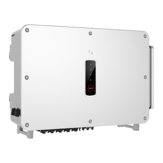
Page 12: Appearance
03 Product Introduction V1.1-2024-06-25 User Manual 3.4 Appearance 3.4.1 Parts Without LCD With LCD 10 11... - Page 13 03 Product Introduction V1.1-2024-06-25 User Manual Parts Description Indicator Indicates working state of the inverter. Button (optional) To control contents displayed on the screen. LCD (optional) To check the parameters of the inverter. To connect the PV module DC input cables. DC Input Terminal GW100K-GT: MPPT1/3/5/7;...
-
Page 14: Dimensions
03 Product Introduction V1.1-2024-06-25 User Manual 3.4.2 Dimensions 300mm 788mm 930mm 3.4.3 Indicators Indicator Status Description ON = EQUIPMENT POWER ON OFF = EQUIPMENT POWER OFF ON = THE INVERTER IS FEEDING POWER OFF = THE INVERTER IS NOT FEEDING POWER SINGLE SLOW FLASH = SELF CHECK BEFORE CONNECTING TO THE GRID SINGLE FLASH = CONNECTING TO THE GRID... -
Page 15: Functionalities
RSD (Optional) The GoodWe RSD signal transmitter communicate with the RSD (Module-level Smart Controller) installed on the external of the PV strings. In case of an emergency, by the way of turning off the AC circuit breaker at the output side of the inverter, the transmitter will be cut off, consequently the current output of the PV strings will be interrupted. - Page 16 03 Product Introduction V1.1-2024-06-25 User Manual Communication The inverter supports: parameter setting via Bluetooth; connection to the SMES monitoring platform via WiFi, 4G, or WiFi+LAN, thus monitoring the operations of the inverter and the power plant, etc. via SMES App. •...
-
Page 17: Inverter Operation Mode
03 Product Introduction V1.1-2024-06-25 User Manual 3.6 Inverter Operation Mode Waiting Mode Fault Mode Upgrading Mode Grid-tied Mode Self-check Mode Mode Description Waiting Waiting stage after the inverter is powered on. • When the conditions are met, the inverter enters the self-check mode. Mode •... -
Page 18: Nameplate
03 Product Introduction V1.1-2024-06-25 User Manual Nameplate The nameplate is for reference only. Goodwe trademark, product type, and product model Technical parameters Safety symbols and certification marks Contact information and serial number... -
Page 19: Check And Storage
04 Check and Storage V1.1-2024-06-25 User Manual 4 Check and Storage 4.1 Check Before Receiving Check the following items before receiving the product. 1. Check the outer packing box for damage, such as holes, cracks, deformation, and others signs of equipment damage. Do not unpack the package and contact the supplier as soon as possible if any damage is found. -
Page 20: Storage
04 Check and Storage V1.1-2024-06-25 User Manual 4.3 Storage If the equipment is not to be installed or used immediately, please ensure that the storage environment meets the following requirements: 1. Do not unpack the outer package or throw the desiccant away. 2. - Page 21 05 Installation V1.1-2024-06-25 User Manual Children No Touch ≥600mm ≥100mm ≥600mm ≥700mm ≥1000mm ≥600mm ALT: 4000m -30~60℃ IP66 0~100% Mounting Support Requirements • The mounting support shall be nonflammable and fireproof. • Make sure that the support surface is solid enough to bear the product weight load. •...
-
Page 22: Inverter Installation
05 Installation V1.1-2024-06-25 User Manual Installation Tool Requirements The following tools are recommended when installing the equipment. Use other auxiliary tools on site if necessary. Safety shoes Socket wrench Goggles Safety gloves Dust mask Diagonal pliers Hammer drill Terminal Wire stripper Heat gun crimping tool Marker... - Page 23 V1.1-2024-06-25 05 Installation User Manual Installing the mounting plate Step 1 Put the mounting plate on the wall horizontally. Step 2 Mark positions for drilling holes. Step 3 Drill holes to a depth of 65mm using the hammer drill. The diameter of the drill bit should be 13mm.
- Page 24 05 Installation V1.1-2024-06-25 User Manual Installing the Inverter NOTICE • Prepare the handles or hoisting rings. Contact the dealer or the after-sales center to purchase them if needed. • Confirm the installation of the handles or hoisting rings are secure enough to bear the weight of the inverter.
-
Page 25: Electrical Connection
06 Electrical Connection V1.1-2024-06-25 User Manual 6 Electrical Connection 6.1 Safety Precautions DANGER • Disconnect the DC switch and the AC output switch of the inverter to power off the equipment before any electrical connections. Do not work with power on. Otherwise, an electric shock may occur. - Page 26 06 Electrical Connection V1.1-2024-06-25 User Manual Cable Specification Cable Type Outer Diameter Cross-sectional Area (mm) 11 ~ 32 PE cable Copper Outdoors cable ≥ S/2* • Copper core : 70 ~ 240 • Aluminum alloy cable or Multi-core output copper-clad aluminum outdoor 22 ~ 64 cable...
-
Page 27: Connecting The Pe Cable
06 Electrical Connection V1.1-2024-06-25 User Manual 6.2 Connecting the PE Cable WARNING • The PE cable connected to the enclosure of the inverter cannot replace the PE cable connected to the AC output port. Both of the two PE cables must be securely connected. •... - Page 28 06 Electrical Connection V1.1-2024-06-25 User Manual Select and Install RCD depending on local laws and regulations. Type A RCDs (Residual Current Monitoring Device) can be connected to the outside of the inverter for protection when the DC component of the leakage current exceeds the limit value. The following RCDs are for reference: Inverter model Recommended RCD specifications GW100K-GT...
- Page 29 06 Electrical Connection V1.1-2024-06-25 User Manual 12.5-13mm A+3mm A+3mm 12.5-13mm Multi-core Multi-core 22-64mm 22-64mm Single-core Single-core 11-32mm 11-32mm Step 1: Crimp the AC cable OT terminal, and prepare the AC output cable. Step 2: Remove the AC terminal cover. Step 3: Select the corresponding hole diameter according to the AC cable diameter specification, and cut off the harf-round part of the plastic pads that is located on the AC terminal cover and inverter.
-
Page 30: Connecting The Pv Input Cable
06 Electrical Connection V1.1-2024-06-25 User Manual 6.4 Connecting the PV Input Cable DANGER • Do not connect the same PV string to multiple inverters, as this may cause damage to the inverter. • The PV strings cannot be grounded. Ensure the minimum isolation resistance of the PV string to the ground meets the minimum isolation resistance requirements before connecting the PV string to the inverter. - Page 31 06 Electrical Connection V1.1-2024-06-25 User Manual DC Input Terminal Connection Manner GW100K-GT When the quantity of PV strings ≤ 8, connect the PV strings to the inverter from MPPT1 to MPPT8 in turn. When the quantity of PV strings >8, please follow the table to connect the PV strings to the inverter.
- Page 32 06 Electrical Connection V1.1-2024-06-25 User Manual GW110K-GT, GW125K-GT When the quantity of PV strings ≤ 10, connect the PV strings to the inverter from MPPT1 to MPPT10 in turn. When the quantity of PV strings >10, please follow the table to connect the PV strings to the inverter.
- Page 33 06 Electrical Connection V1.1-2024-06-25 User Manual Connecting the DC Input Cable Step 1 Prepare DC cables. Step 2 Crimp the DC cable and assemble the PV connectors. Step 3 Fasten the PV connector. Step 4 Measure the DC input voltage. Step 5 Plug the PV connectors into the DC input terminals.
-
Page 34: Communication
06 Electrical Connection V1.1-2024-06-25 User Manual 6.5 Communication 6.5.1 RS485 Communication Networking NOTICE • If multiple inverters are connected to the EzLogger 3000C for networking, the maximum number of inverters per COM port of the EzLogger 3000C is 20, and the total length of the connecting cable should not exceed 1000m. - Page 35 06 Electrical Connection V1.1-2024-06-25 User Manual WARNING 1. The place to snap fit the CT shall be near the grid connection point and the installation direction must be right. “-->” of CT refers that the inverter current flows to the Grid. If CT is installed reversely, the inverter will be triggered with an alarm and unable to realize the power limit function.
- Page 36 06 Electrical Connection V1.1-2024-06-25 User Manual GM330 Power export limit of single inveter with Load Inverter Grid Circuit Meter Circuit Breaker Breaker GM330 RS485A-1 RS485B-1 EzLogger 3000C+GM330 Power export limit of multi inveters with Load Inverter 1 Inverter N ..Grid Circuit Meter...
-
Page 37: Connecting The Communication Cable
06 Electrical Connection V1.1-2024-06-25 User Manual 6.5.3 Connecting the Communication Cable NOTICE • The communication port can be configured differently according to the regulatory requirements in different regions. • The remote shutdown function is diabled in default. Enable it via SolarGo App if needed. Detailed steps, refer to SolarGo App User Manual. - Page 38 06 Electrical Connection V1.1-2024-06-25 User Manual Function Definition Description RS485 1B • To connect with the smart meter or • To connect DER-AVM device (for South RS4851A Korea only) Ground RS485 2B RS485 RS485 2A To connect with multi inverters or the smart DataLogger (Ezlogger 3000C).
-
Page 39: Installing The Communication Module
WiFi+LAN module. Set inverter parameters, check running information and fault information, and observe system status in time via the smartphone or web pages. NOTICE Refer to the delivered communication module user manual to get more introduction to the module. For more detailed information, visit https://en.goodwe.com/. -
Page 40: Equipment Commissioning
07 Equipment Commissioning V1.1-2024-06-25 User Manual 7 Equipment Commissioning 7.1 Check Items before Power On Check Item The inverter is firmly installed in a clean place where is well-ventilated and easy to operate. The PE cable, DC input cable, AC output cable, and communication cable are connected correctly and securely. -
Page 41: System Commissioning
08 System Commissioning V1.1-2024-06-25 User Manual 8 System Commissioning 8.1 Indicators and Button Indicator Status Description ON = EQUIPMENT POWER ON OFF = EQUIPMENT POWER OFF ON = THE INVERTER IS FEEDING POWER OFF = THE INVERTER IS NOT FEEDING POWER SINGLE SLOW FLASH = SELF CHECK BEFORE CONNECTING TO THE GRID SINGLE FLASH = CONNECTING TO THE GRID... -
Page 42: Setting Inverter Parameters Via Lcd
08 System Commissioning V1.1-2024-06-25 User Manual 8.2 Setting Inverter Parameters via LCD NOTICE • The screen shots are for reference only. The actual display may differ. • The name, range, and default value of the parameters is subject to change or adjust. The actual display prevails. - Page 43 08 System Commissioning V1.1-2024-06-25 User Manual First level menu Second level menu Long press Normal for 2s Set language Pac=xxx W Set Safety Short press Short press xxxx-xx-xx Set Date xx:xx:xx Set Time Short press Short press Vpv1-3(4-6/7-9/10)= W/L Reset xx/xx/xxV W/L Reload Short press...
-
Page 44: Inverter Parameter Introduction
08 System Commissioning V1.1-2024-06-25 User Manual 8.2.2 Inverter Parameter Introduction Parameters Description Normal Home page. Indicates the real-time power of the inverter. 2022-02-14 Check the time of the country/region. 09:01:10 VPv1 Check the DC input voltage of the inverter. IPv1 Check the DC input current of the inverter. - Page 45 08 System Commissioning V1.1-2024-06-25 User Manual Parameters Description With LVRT on, the inverter will stay connected with the utility grid LVRT after a short-term utility grid low voltage exception occurs. With HVRT on, the inverter will stay connected with the utility grid HVRT after a short-term utility grid high voltage exception occurs.
-
Page 46: Setting Inverter Parameters Via App
2. Set grid parameters and communication parameters of the inverter. 3. Maintain the equipment. For more details, refer to the SolarGo APP User Manual. Scan the QR code or visit https:// en.goodwe.com/Ftp/EN/Downloads/User%20Manual/GW_SolarGo_User%20Manual-EN.pdf get the user manual. SolarGo App SolarGo App User Manual 8.4 Monitoring via SEMS Portal... -
Page 47: Maintenance
V1.1-2024-06-25 09 Maintenance User Manual 9 Maintenance 9.1 Power Off the Inverter DANGER • Power off the inverter before operations and maintenance. Otherwise, the inverter may be damaged or electric shocks may occur. • Delayed discharge. Wait until the components are discharged after power off. Step 1 (Recommended) sand a command to the inverter for halting the grid via SolarGo APP. -
Page 48: Troubleshooting
09 Maintenance V1.1-2024-06-25 User Manual 9.4 Troubleshooting Perform troubleshooting according to the following methods. Contact the after-sales service if these methods do not work. Collect the information below before contacting the after-sales service, so tha the problems can be solved quickly. 1. - Page 49 V1.1-2024-06-25 09 Maintenance User Manual No. Fault Cause Solutions If occurs occasionaly, it may be caused a short term grid abnormity. The inverter will recover automatically after the grid is normal. If it occurs frequently, please check whether the grid voltage is within the allowed range.
- Page 50 09 Maintenance V1.1-2024-06-25 User Manual No. Fault Cause Solutions If occurs occasionaly, it may be caused a short term grid abnormity. The inverter will recover automatically after the grid is normal. If it occurs frequently, please check whether the grid voltage is within The frequency of the grid the allowed range.
- Page 51 V1.1-2024-06-25 09 Maintenance User Manual No. Fault Cause Solutions Abnormal grid, and If occurs occasionaly, it may the abnormal duratin be caused a short term grid LVRT exceeds the specified abnormity. The inverter will recover Undervoltage value of local high automatically after the grid is voltage safety regulation.
- Page 52 09 Maintenance V1.1-2024-06-25 User Manual No. Fault Cause Solutions 1. The PE cable is not 1. Please confirm if the PE cable of the connected. inverter is not connected properly. 2. When ground the PV 2. Under the scenerio of PV string Abnormal Ground.
- Page 53 V1.1-2024-06-25 09 Maintenance User Manual No. Fault Cause Solutions AC HCT Check Abnormal sampling of abnormal AC HCT GFCI HCT Check Abnormal sampling of abnormal GFCI HCT 1. The relay is abnormal or short-circuited. 2. The control circuit is abnormal. Relay Check 3.
- Page 54 09 Maintenance V1.1-2024-06-25 User Manual No. Fault Cause Solutions The reference circuit is 1.5V Ref abnormal abnormal. The reference circuit is 0.3V Ref abnormal abnormal. BUS Overvoltage P-BUS Overvoltage N-BUS Overvoltage 1. The PV voltage is too high. Overvoltage(Slave 2. The sampling of the Disconnect the AC output switch and CPU 1) inverter BUS voltage is...
- Page 55 V1.1-2024-06-25 09 Maintenance User Manual No. Fault Cause Solutions 1. If the problem occurs occasionally, the PV voltage Low reason might be abnormal sun light. The inverter will recover automatically without Sun light is weak or manual intervention. changing abnormally. BUS voltage Low 2.
-
Page 56: Routine Maintenance
09 Maintenance V1.1-2024-06-25 User Manual 9.5 Routine Maintenance DANGER Power off the inverter before operations and maintenance. Otherwise, the inverter may be damaged or electric shocks may occur. Maintaining Item Maintaining Method Maintaining Period Check the heat sink, air intake, and air System Clean Once 6-12 months outlet for foreign matter or dust. - Page 57 Follow below steps to maintain the fans of GT inverters: GT Series inverter is equipped with outside fans on its left side. The fan should be cleaned yearly with a vacuum cleaner. For more thorough cleaning, completely remove the fans.
-
Page 58: Technical Parameters
10 Technical Parameters V1.1-2024-06-25 User Manual 10 Technical Parameters Technical Data GW100K GW110K GW125K Input(DC) Max.Input Power (kW) 187.5 Max.Input Voltage(V) 1100 1100 1100 MPPT Operating Voltage Range (V) 180~1000 MPPT Voltage Range at Nominal Power (V) 500~850 Start-up Voltage (V) Nominal Input Voltage (V) Max. - Page 59 V1.1-2024-06-25 10 Technical Parameters User Manual Technical Data GW100K GW110K GW125K Maximum Output Overcurrent Protection Efficiency Max. Efficiency 98.8% 98.8% 99.0% European Efficiency 98.4% 98.4% 98.5% CEC Efficiency 98.3% 98.3% 98.4% Protection PV String Current Monitoring Integrated PV Insulation Resistance Detection Integrated Residual Current Monitoring Integrated...
- Page 60 10 Technical Parameters V1.1-2024-06-25 User Manual Technical Data GW100K-GT GW110K-GT GW125K-GT General Data Operating Temperature Range (℃) -30 ~ +60 Storage Temperature (℃) -40 ~ +70 Relative Humidity 0 ~ 100% Max. Operating Altitude (m) 4000 Cooling Method Smart Fan Cooling User Interface LED, LCD (Optional ) ,WLAN+APP Communication...
- Page 61 V1.1-2024-06-25 10 Technical Parameters User Manual Overvoltage levels: Overvoltage I: Devices connected to the circuit which can limit instantaneous overvoltage to a relatively low level. Overvoltage II: Energy-consuming devices powered by fixed power distribution equipment, including appliances, portable tools, and other household and similar equipment. Overvoltage III is also applicable if there are special requirements for the reliability and applicability of the equipment.
- Page 62 GoodWe Website GoodWe Technologies Co., Ltd. No. 90 Zijin Rd., New District, Suzhou, 215011, China www.goodwe.com Local Contacts service@goodwe.com...
Need help?
Do you have a question about the GT Series and is the answer not in the manual?
Questions and answers