Table of Contents
Advertisement
Quick Links
Advertisement
Table of Contents

Related Manuals for Robe Anolis Agame


Summary of Contents for Robe Anolis Agame
- Page 1 QR code for user manual Version 1.0...
-
Page 2: Table Of Contents
Agame Table of contents 1. Safety instructions ..............................3 2. Fixture exterior view ..............................5 3. Control and connection .............................. 5 4. Installation .................................. 8 4.1 Mounting the fixture ............................8 4.2 Connection to power ............................11 4.3 Example of Control panel in RDM manager ......................16 5. -
Page 3: Safety Instructions
Agame FOR YOUR OWN SAFETY, PLEASE READ THIS USER MANUAL CAREFULLY BEFORE POWERING OR INSTALLING YOUR Agame ! Save it for future reference. This device has left our premises in absolutely perfect condition. In order to maintain this condition and to ensure safe operation, it is absolutely necessary for the user to follow the safety instructions and warnings written in this manual. - Page 4 Agame Please use the original packaging if the fixture is to be transported. If this device will be operated in any way different to the one described in this manual, the product may suffer damages and the warranty becomes void. Furthermore, any other operation may lead to dangers like short-circuit, burns, electric shock etc.
-
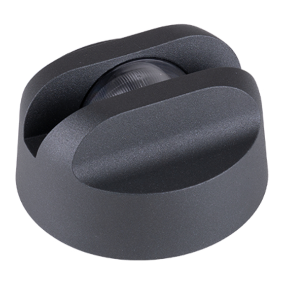
Page 5: Fixture Exterior View
Agame 2. Fixture exterior view Standard version Rear version 1. Transparent plastic cover 2. Supply cable 3. Top cover 4. Stainless steel base 3. Control and connection The Agame modules should be connected to the E-Box Remote or E-Box Remote basic via junction boxes. The Agame modules have to be operated in Pass-Through mode. - Page 6 Agame Example of connection with E-box Remote Basic Note. Combination of Agames amd Calummas XS or Emineres Remote is possible. Example: From point of view of driver load (E-box Remote/E-box Remote Basic), max. number of Agames connected to one E-box Remote/E-box Remote Basic is 40 but Agames have to be operated in the Pass-through mode, it means that max.
- Page 7 Agame E-box Remote Basic Cable length * Max. number of Agames 50 m 100 m * Cable length is a total cable length on both LED outputs. Example: Total cable length=L1+L2+L3+L4+L5+L6+L7+L8+L9...
-
Page 8: Installation
Agame 4. Installation 4.1 Mounting the fixture 1. Remove the top cover (3) from the fixture. The top cover is fastened to the base (4) by means of two spring locks in this cover and you do not need any instruments to remove it . Push your thubs on the plastic cover (1) and by means of your fingers pull the top cover (3) up. - Page 9 Agame The Agame can be fastened in any orientation on a flat, non-flammable surface by means of two mounting openings (6). For the rear version of the Agame, prepare suitable hole for cable gland (7) in the mounting surface. The three adjusting screws (8) allows you to align the base of Agame in a horizontal plane, use an Allen key 2.5 adjusting the plane of the Agame base.
- Page 10 Agame Top side of the base Bottom side of the base Ensure that the structure to which you are attaching the fixture is secure.
-
Page 11: Connection To Power
Agame 4.2 Connection to power The unit must be installed by a qualified electrician in accordance with all national and local electrical and construction codes and regulations. Junction box installation Junction box with one output Junction box with four outputs 1.Unscrew the four screws (1) from the cover (2) on the junction box to get access to the DPS with terminal blocks (3) and two mounting holes (4). - Page 12 Agame 3. Connect cables to terminal blocks. Two cable glands M20 x 1.5 serves for a power/data cable. One (or four) cable gland M12 x 1.5 serves for Agame connection cable. Remove the end cap from the cable gland before passing the cable. We recommend to apply an adequate layer of the paste LOCTITE 5331 on the plastic holder of the cable gland before inserting it into the body of the gland.
- Page 13 Agame Wiring of connection blocks on DPS RB4233 in the junction box with four LED outputs. Fuse F1-F4: 2A/500V AC. Agame connection Connector Function LEDs + Data + Data - LEDs - Not connected Colour of wire Orange White Black Colours of wires apply to the 5-cored cable UL 20969 5x 20AWG (P/N 13053481) Connector Function...
- Page 14 Agame Connector Function LEDs + Data + Data - LEDs - Ground Colour of wire Orange White Black Yellow/green Colours of wires apply to the 5-cored cable SJTW 5x 14AWG (P/N 1305 3336). NOTE: Each DMX line of Agames connected to the LED output of the E-box Remote has to be terminated at the last fixture.
- Page 15 Agame 4. Screw the cover (2) back on the junction box.
-
Page 16: Example Of Control Panel In Rdm Manager
Agame 4.3 Example of Control panel in RDM manager The software RDM manager is available on the ROBE website (https://www.robe.cz/support), product RUNIT WTX. Green arrow saves changes made in the Control panel to the Agame. - Page 17 Agame Manufacturer PIDs LED calibration 4byte HEX! (RGBW/RGBA) - the item shows 4 bytes of calibration values for calibrated white colours of RGBW(RGBA) Agame. E.g. CTC channel has to be set to some calibrated white colour (21 DMX-1800K, 66 DMX-2700K, 91 DMX-3200K, 141 DMX-4200K, 211 DMX-5600K, 255 DMX-6500K) otherwise the item shows values "ff ff ff ff"...
-
Page 18: Software Update
Agame 5. Software update Software update of Agame modules has to be done by means of the software ROBE Uploader running on PC. The ROBE Uploader is a software for automatized software update of ROBE fixtures. The ROBE Uploader switches Agames to the update mode automatically. - Page 19 Agame 2. By means of the Ethernet connection...
-
Page 20: Technical Specifications
Agame 6. Technical specifications Power supply • Input voltage: 48 V • Power consumption: 8 W Optical • Light source: 4 high power LEDs • Colour variants: RGBW (W - 6500 K), RGBA • Beam width: 6°, 10°, 20°, 30° •... - Page 21 Agame Dimensions (All dimensions in mm [inch]) Standard version...
- Page 22 Agame Rear version...
- Page 23 Agame Junction box with one output Junction box with four outputs...
-
Page 24: Cleaning And Maintenance
Version of manual Date of issue Description of changes Specifications are subject to change without notice. August 21, 2024 Copyright © 2024 Robe Lighting - All rights reserved Made in CZECH REPUBLIC by ROBE LIGHTING s.r.o. Palackeho 416/20 CZ 75701 Valasske Mezirici... - Page 25 DMX protocol DMX protocol for Agame Version: 1.0 (16 modes in total) Mode/Channels in all Mode 1- RGBW(A)-8bit, Mode 2- RGB 8-bit, Mode 3- full RGBW(A) 8-10 Mode 4- White-full control, Mode 5- Reduced RGBW(A) Reserved Mode 6- Reduced RGBW(A)+white control, Mode 7- Full control Mode 7-Full RGBW(A)+virt.
- Page 26 DMX protocol Mode/channels Function DMX Value Type of control White 1800 K step White 2700 K step White 3200 K step White 4200 K step 9-10 White 5600 K step 11-12 White 6500 K step Blue (Blue=full, Red+Green+White/Amber=0) step 14-23 proportional Red=0, Green->up,Blue =full, White/Amber=0 step...
- Page 27 224-255 Shutter open step Dimmer 0 - 255 Light intensity coarse (0-100%) proportional Dimmer Fine 0 - 255 Light intensity fine proportional Copyright © 2024 Robe Lighting s.r.o. - All rights reserved All Specifications subject to change without notice Page 3...
- Page 28 Dimmer 0 - 255 Light intensity coarse (0 - 100%) proportional Dimmer Fine 0 - 255 Light intensity fine proportional Copyright © 2024 Robe Lighting s.r.o. - All rights reserved All Specifications subject to change without notice Page 4...
Need help?
Do you have a question about the Anolis Agame and is the answer not in the manual?
Questions and answers