Table of Contents
Advertisement
Quick Links
Advertisement
Table of Contents

Related Manuals for Shini SHD-E-EC


Summary of Contents for Shini SHD-E-EC
- Page 1 SHD-E-EC Hopper Dryer Date:Jun., 2023 Version:Ver. C...
-
Page 2: Table Of Contents
Content 1. General Description ..................4 1.1 Coding Principle ..................5 1.2 Feature ..................... 5 1.3 Options ..................... 5 1.4 Safety Regulations ................... 7 1.4.1 Safety Signs and Labels ............... 8 1.4.2 Sign and Labels ................8 1.5 Exemption Clause ..................9 2. - Page 3 4.5.2 Recipe list ................... 26 4.5.3 Trouble Table ................27 5. Troubleshooting .................... 29 6. Maintenance and Repair ................30 6.1 Maintenance Schedule ................31 6.1.1 General Machine Information ............. 31 6.1.2 Installation & Inspection .............. 31 6.1.3 Daily Checking ................31 6.1.4 Weekly Checking ................
-
Page 4: General Description
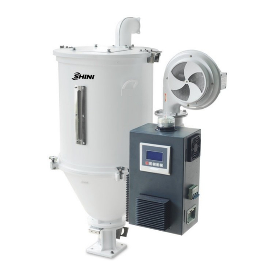
1. General Description Please read through this operation manual before using the machine to prevent damages of the machine or personal injuries. Picture 1-1:Hopper Dryer SHD-50E-EC 4(31) -
Page 5: Coding Principle
1.1 Coding Principle 1.2 Feature 1) Adopt hot air diffuser to keep plastics dry and temperature stable, thus improving drying efficiency. 2) All material contact surfaces are made of stainless steel to eliminate material contamination. 3) All models are equipped with external power switch. 4) For SHD-25E-EC~150E-EC, heater pipes are connected by lead sheets and other models are equipped with temperature protector to prevent heater pipe from damaging by blower fault. - Page 6 Chapter 5, which contains service instructions intended for service engineers. Other chapters contain instructions for the daily operator. Any modifications of the machine must be approved by SHINI in order to avoid personal injury and damage to machine. We shall not be liable for any damage caused by unauthorized change of the machine.
-
Page 7: Safety Regulations
Table 1‑1:Dryer drying capacity(kg/hr)(Selection guide) Notes: Based on relative humidity 65% with ambient temperature of 20℃,moisture content after drying can be 0.2% ro less. 1.4 Safety Regulations 7(31) -
Page 8: Safety Signs And Labels
Note: Electrical installation should be done by qualified electrician only. Before connecting to AC Power Source, turn power switch to OFF position. While AC power source is connected, make sure specifications and overload protection rating of the power switch are suitable and reliable. When the machine is under care or maintenance, turn off both power switch and automatic operation switch. -
Page 9: Exemption Clause
The following statements clarify the responsibilities and regulations born by any buyer or user who purchases products and accessories from Shini (including employees and agents). Shini is exempted from liability for any costs, fees, claims and losses caused by reasons below: 1) Any careless or man-made installations, operation and maintenances upon machines without referring to the Manual prior to machine using. -
Page 10: Structure Characteristics And Working Principle
2. Structure Characteristics and Working Principle 2.1 Working Principle Picture 2‑1 Working principle In the drying process, the hopper dryer adjusts the blower frequency (2) according to the exhaust air temperature. The high-temperature air is blown into the drying hopper (7) through the hot air pipe (4), and evenly dispersed to the materials inside the drying hopper via the shade separator(5) and screen separator(6) to take away the moisture of materials in the hopper through the air outlet pipe (1), thus achieving the moisture removal purpose. -
Page 11: Installation And Debugging
3. Installation and Debugging Notes for Installation and Positioning: 1) Machine just can be mounted in vertical position. Make sure there’s no pipe, fixed structure or other objects above the installing location and around the machine which may block machine’s installation, hit objects or injure human person. -
Page 12: The Hopper Dryer Test
1) Make sure the voltage and frequency of the power source comply with those indicated on the manufacturer nameplate that attached to the machine. 2) Power cable and earth connection should conform to your local regulations. 3) Use independent electrical wires and power switch. Diameter of electrical wire should not be less than those used in the control box. -
Page 13: Options And Installation(Purchased Separately
3.4 Options and Installation(purchased separately) 3.4.1 Installing the air-exhaust filter ADC If the materials contain dust or to avoid the dust-contain air exhausted by dryer polluting the workshop’s environment. Option with air-exhaust filter ADC can filter the exhausted air from the dryer. ADC can reach filter efficiency of 99%. ADC is installed on air-exhaust elbow of the dryer. -
Page 14: Blower Inlet Filter Aif Installation
suction box and shut-off suction box is simple. Install them at bottom of the hopper, point to the holes and tighten up the screws. Picture 3-4: Shut-off Suction Box SBU 3.4.3 Blower Inlet Filter AIF Installation When dryers in the dust-contain environment or hot air requires high cleanliness, it can option with AIF blower inlet filter. -
Page 15: N-Type Floor Stand Fsn Installation
the corresponding screws. With the hot air recycler, it can save up to 40% energy consumption. Picture 3-6:Hot Air Recycler HAR 3.4.5 N-type floor stand FSN Installation It helps to move the main body of the drying hopper out of the injection moulding workshop and is suitable for height limited plant. - Page 16 Picture 3-8:Hopper Magnet MR 16(31)
-
Page 17: Operation Guide
4. Operation Guide 4.1 Control Panel Information display area Page up Keys Select parameters up Prompt area Increment value On-off key Reduce the value Page down Select parameters down Shift Cancel Return to Enter User menu reset Noise Suppressor Status indicator Picture 4‑1:Control Panel Table4-1:Control Panel ICONS... -
Page 18: Common Interface
Appointment On: The reservation timing function is enabled timing icon Off: The reservation timing function is disabled Heat Lit: The unit is in Heat preservation mode Preservation Off: The unit is not in Heat preservation mode Mode icon Lit: PID parameter self-tuning is on Self-setting icon Off: PID parameter self-tuning is off Steady yellow: Stop/In stopping... - Page 19 All startups are performed on the "Main operation interface". The corresponding icon indicates the relevant status. If the drying temperature now is 20 ° C and the drying temperature is set to 90 ° C (During operation, the blower and heating are on, the timing function is enabled, and the temperature lock is enabled), the "main operation interface"...
-
Page 20: Fault Screen
4.2.2.3 The timing time is displayed on the main screen Note: If there is no timed startup, the time is displayed 00:00. 4.2.2.4 ECO Mode/Insulation Mode After the first start-up and the drying time, when the air exhaust set temperature > the actual temperature, and the anti-excessive drying time (default 30 minutes) is over, the unit will enter the ECO mode. -
Page 21: Delayed Shutdown And Standby Interface
Picture 4-3:Fault screen 4.2.3.1 Fault query/reset interface When the fault occurs, the alarm interface will automatically pop up. The fault query and reset operation are as follows: 4.2.4 Delayed shutdown and standby interface 4.2.4.1 Delay stop interface Note: In the case of delayed shutdown, the main interface and the delayed shutdown interface are alternately displayed every 2 seconds until the shutdown countdown is over. -
Page 22: User Menu
4.3 User Menu Press <Menu> key in the main interface to enter the user menu, the user menu parameters are as follows: Table4-2:User Menu Parameter Table Serial No. Parameter Items Parameter Function Remarks Set user parameters User Settings in the Set the shutdown time relevant parameter User settings... -
Page 23: Parameter Table
4.5 Parameter Table 4.5.1 User Parameter Setting Table Table4-3:User Parameter Setting Table Serial No. Items Initial Value Set Range Units Remarks User parameters (public) : On the home screen, press the "Menu" key to enter the menu. Select User Settings in the menu bar and press the "Set"... - Page 24 No: The setting temperature can be quickly modified from the home screen. Lock the temperature Yes/No Yes: The set temperature can’t be quickly modified on the home screen. This parameter is displayed only Self-tuning Disabled Disable/use when the machine is running Chinese Multiple languages Chinese...
- Page 25 00:00 to Saturday shutdown time: 00:00 23:59 00:00 to Sunday shutdown time: 00:00 23:59 Boot time parameters (public) : Press the "Menu" key from the home screen to enter the menu. Select User Settings in the menu bar and press the "Set" key to access. Select the boot time and press the "Set" key to enter. Press the "Up" or "Down"...
-
Page 26: Recipe List
No parity / Odd parity / Check bit parity Even parity Data length Stop bit 1 ~ 2 4.5.2 Recipe list Table4-4:Recipe List Exhaust air Groups Ingredients Drying time (min) Drying temperature (℃) temperature (° C) PETG PMMA PEEK 26(31) -
Page 27: Trouble Table
Note: Under the condition that the moisture content of materials meets the standard, decrease the exhaust air temperature appropriately can improve the energy-saving effect. 4.5.3 Trouble Table This controller has various alarm functions. When a failure occurs, the alarm interface displays the current fault. The specific fault code meaning is shown in the following Table. - Page 28 The machine continues to run when the alarm is given. After the fault is removed, the machine automatically resets. No battery. The alarm is detected only when the reservation timing function is enabled. Start detection as soon as it is powered on Stop heating, delay stop blower, trip output 5 seconds.
-
Page 29: Troubleshooting
5. Troubleshooting Table 5‑1:Common Faults and Troubleshooting Fault Possible Reasons Solution 1. Thermocouple poor contact. 1. Check and connect it closely. Probe failure 2. Thermocouple wire broken. 2. Check and replace. 1. Temp. control large error or fault of the 1. -
Page 30: Maintenance And Repair
6. Maintenance and Repair 1.Check whether the screw and nut are loose. Cycle: weekly. 1.Check whether the hopper cover 2.Clean the inner and outer blower handle, handle hook, hopper hinge (especially the air inlet tunnel), and cover hinge are loose. remove foreign objects from the blower Cycle: Monthly. -
Page 31: Maintenance Schedule
6.1 Maintenance Schedule 6.1.1 General Machine Information Model Manufacture date Ф Voltage Frequency Power 6.1.2 Installation & Inspection Check if the pipe joint is tightly locked by clips or not. Check that the material clearance door is firmly closed. Check that the piping system is correctly connected. Electrical Installation Voltage Fuse melt current: 1Phase...
Need help?
Do you have a question about the SHD-E-EC and is the answer not in the manual?
Questions and answers