Table of Contents
Advertisement
Advertisement
Table of Contents

Subscribe to Our Youtube Channel
Related Manuals for Shini SHD-EB Series


Summary of Contents for Shini SHD-EB Series
- Page 1 SHD-EB Budget Hopper Dryer Date: Mar, 2017 Version: Ver.A...
-
Page 3: Table Of Contents
Content General Description ..................7 1.1 Coding Principle ..................8 1.2 Feature....................8 1.3 Technical Specifications................ 10 1.3.1 External Dimensions..............10 1.3.2 Specification ................10 1.4 Safety Regulations ................12 1.4.1 Safety Signs and Labels .............. 12 1.4.2 Signs and Labels ................. 13 1.5 Exemption Clause ................. - Page 4 3.5.3 Blower Inlet Filter Installation............43 3.5.4 Hot Air Recycler Installation............44 Operation Guide ..................45 4.1 Control Panel ..................45 4.1.1 Panel Operation................45 4.1.2 Setting Temperature..............45 4.2 Control Panel with Dryer ............... 47 4.2.1 Panel Operation................48 4.2.2 Timer Setting ................
- Page 5 Table 2-17: Electrical Components List (SHD-200H-EB)........39 Picture Index Picture 1-1: External Dimensions..............10 Picture 2-1: Working Principle ................14 Picture 2-2: Assembly Drawing (SHD-25~75-EB)..........15 Picture 2-3: Assembly Drawing (SHD-100/150-EB).......... 17 Picture 2-4: Assembly Drawing (SHD-200-EB)..........19 Picture 2-5: Electrical Diagram (SHD-12/12H-EB)..........22 Picture 2-6: Electrical Diagram (SHD-25~150H-EB).........
- Page 6 6(49)
-
Page 7: General Description
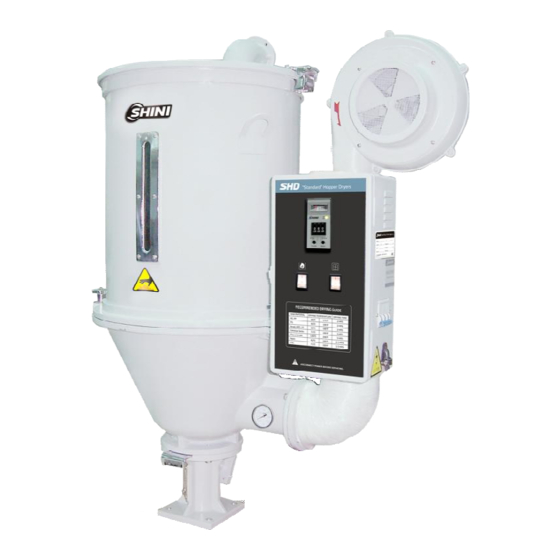
1. General Description Please read through this operation manual before using the machine to prevent damages of the machine or personal injuries. SHD-50-EB 7(49) -
Page 8: Coding Principle
1.1 Coding Principle 1.2 Feature Ÿ Adopt hot air diffuser to gain an even hot air flow to improve drying efficiency. Ÿ Hot air inlet elbow design can prevent dust piling up at bottom of the pipe heaters so as to avoid burning. Ÿ... - Page 9 Chapter 5, which contains service instructions intended for service engineers. Other chapters contain instructions for the daily operator. Any modifications of the machine must be approved by SHINI in order to avoid personal injury and damage to machine. We shall not be liable for any damage caused by unauthorized change of the machine.
-
Page 10: Technical Specifications
1.3 Technical Specifications 1.3.1 External Dimensions Picture 1-1: External Dimensions 1.3.2 Specification Table 1-1: Specification Mode SHD-25-EB SHD-50-EB SHD-100-EB SHD-200-EB Heater(kW) 3/3.3* 3.9/4.2* 6/6.6* 12/15* Blower(kW) 0.12 0.12 0.12 0.18 Loading Capacity (kg) H(mm) 1015 1145 1340 1332 H1(mm) 1045 1340 1332 H2(mm) - Page 11 Table 1-2: Dryer Drying Capacity(kg/hr)(Selection Guide) Mode Drying Drying SHD-25-EB SHD-50-EB SHD-100-EB SHD-200-EB Time Temp. Material Polystyre (PS) 0.75hrs 80℃ Polyethylen 0.75hrs 80℃ (PE) Poly propyrene 0.75hrs 80℃ (PP) Poly styrence 1hrs 80℃ H·D 1hrs 80℃ 4hrs 75℃ Nylon 11,12 5hrs 75℃...
-
Page 12: Safety Regulations
1.4 Safety Regulations 1.4.1 Safety Signs and Labels Note! Electrical installation should be done by qualified electrician only. Before connecting to AC Power Source, turn power switch to OFF position. While AC power source is connected, make sure specifications and overload protection rating of the power switch are suitable and reliable. -
Page 13: Signs And Labels
Shini (including employees and agents). Shini is exempted from liability for any costs, fees, claims and losses caused by reasons below: 1. Any careless or man-made installations, operation and maintenances upon machines without referring to the Manual prior to machine using. -
Page 14: Structure Characteristics And Working Principle
2. Structure Characteristics and Working Principle 2.1 Working Principle Picture 2-1: Working Principle In the drying process, hot air with constant temperature is blown by the drying blower 2 of SHD into the drying hopper 7 to dry the materials. Moisture will be separated out and taken away by hot air, thus to gain a satisfied drying effect. -
Page 15: Drawing And Parts List
2.2 Drawing and Parts List 2.2.1 Assembly Drawing (SHD-25~75-EB) Remarks:Please refer to material list 2.2.2 for specific explanation of theArabic numbers in parts drawing. Picture 2-2: Assembly Drawing (SHD-25~75-EB) 15(49) -
Page 16: Parts List (Shd-25~75-Eb)
2.2.2 Parts List (SHD-25~75-EB) Table 2-1: Parts List (SHD-25~75-EB) Part NO. Name SHD-25-EB SHD-50-EB SHD-75-EB Control box** BH31002509550 BH31005006550 BH31007506550 Hot-air pipe** BA10002500410 BA10005000610 BA10005000610 Pipe heater*(SHD) BH70250300150 BH70500300150 BH70750300050 Pipe heater **(SHD-H) BH70253300010 BH70007500510 BH70754800010 Blower* YM40002501150 YM40000300900 YM40000300900 Storage hopper BK01002500020 BK01005000020... -
Page 17: Assembly Drawing (Shd-100/150-Eb)
2.2.3 Assembly Drawing (SHD-100/150-EB) Remarks:Please refer to material list 2.2.4 for specific explanation of theArabic numbers in parts drawing. Picture 2-3: Assembly Drawing (SHD-100/150-EB) 17(49) -
Page 18: Parts List (Shd-100/150-Eb)
2.2.4 Parts List (SHD-100/150-EB) Table 2-2: Parts List (SHD-100/150-EB) Part NO. Name SHD-100-EB SHD-150-EB Control box* BH31010006550 BH31015006550 Hot-air pipe** BA10010000610 BA10010000610 Pipe heater**(SHD) BH70103800050 BH70153800050 Pipe heater**(SHD-H) BH70153800050 BH70150720010 Blower* YM40000400900 YM40000400900 Storage hopper BK01010000020 BK01015000020 Rear hinge at cover YW06102000000 YW06102000000 Exhaust pipe... -
Page 19: Assembly Drawing (Shd-200-Eb)
2.2.5 Assembly Drawing (SHD-200-EB) Remarks:Please refer to material list 2.2.6 for specific explanation of theArabic numbers in parts drawing. Picture 2-4: Assembly Drawing (SHD-200-EB) 19(49) -
Page 20: Parts List (Shd-200-Eb)
2.2.6 Parts List (SHD-200-EB) Table 2-3: Parts List (SHD-200-EB) Part NO. Name Control box** BH31020006950 Hot-air pipe** BA10020000610 Pipe heater**(SHD) YW90001201500 Blower* YM40000500900 Rear hinge at cover YW09102000100 Storage hopper BK01020000020 Hopper cover BW09020000020 Cover fastener YR10002500200 Exhaust pipe BA10020000210 Handle hook YW00251000000 Handle... -
Page 21: Circuit Diagram
2.3 Circuit Diagram 2.3.1 Power, Diameter, Current 21(49) -
Page 22: Electrical Diagram
2.3.2 Electrical Diagram Picture 2-5: Electrical Diagram (SHD-12/12H-EB) 22(49) -
Page 23: Picture 2-6: Electrical Diagram (Shd-25~150H-Eb)
Picture 2-6: Electrical Diagram (SHD-25~150H-EB) 23(49) -
Page 24: Picture 2-7: Electrical Diagram (Shd-200/200H-Eb)
Picture 2-7: Electrical Diagram (SHD-200/200H-EB) 24(49) -
Page 25: Electrical Components Layout
2.3.3 Electrical Components Layout Picture 2-8: Electrical Components Layout 25(49) -
Page 26: Electrical Components List
2.3.4 Electrical Components List Table 2-4: Electrical Components List (SHD-12-EB) 26(49) - Page 27 Table 2-5: Electrical Components List (SHD-12H-EB) 27(49)
- Page 28 Table 2-6: Electrical Components List (SHD-25-EB) 28(49)
- Page 29 Table 2-7: Electrical Components List (SHD-25H-EB) 29(49)
- Page 30 Table 2-8: Electrical Components List (SHD-50-EB) 30(49)
- Page 31 Table 2-9: Electrical Components List (SHD-50H-EB) 31(49)
- Page 32 Table 2-10: Electrical Components List (SHD-75-EB) 32(49)
- Page 33 Table 2-11: Electrical Components List (SHD-75H-EB) 33(49)
- Page 34 Table 2-12: Electrical Components List (SHD-100-EB) 34(49)
- Page 35 Table 2-13: Electrical Components List (SHD-100H-EB) 35(49)
- Page 36 Table 2-14: Electrical Components List (SHD-150-EB) 36(49)
- Page 37 Table 2-15: Electrical Components List (SHD-150H-EB) 37(49)
- Page 38 Table 2-16: Electrical Components List (SHD-200-EB) 38(49)
- Page 39 Table 2-17: Electrical Components List (SHD-200H-EB) 39(49)
-
Page 40: Installation And Debugging
3. Installation and Debugging Notes for Installation and Positioning: 1) Machine just can be mounted in vertical position. Make sure there’s no pipe, fixed structure or other objects above the installing location and around the machine which may block machine’s installation, hit objects or injure human person. -
Page 41: Floor Stand Installation
3.2 Floor Stand Installation Picture 3-2: Floor stand Installation Floor stand installation type is to mount dryer on a floor stand, then via a photo-sensor hopper receiver to convey the material to the feed port of a molding machine. SHD-400 and above models should adopt floor stand installation type. Machine should be placed on water-level floor to keep balance. -
Page 42: The Hopper Dryer Test
3.4 The Hopper Dryer Test After ensuring all the circuits have been connected firmly, turn on the blower switch to” ON” status and turn on the heater switch on control box to “ON” status. Then light indicator of the switch would turn on, observe whether the rotating derection of the blower is same as the arrow indicated direction. -
Page 43: Suction Box Installation
3.5.2 Suction Box Installation Picture 3-5: European Suction Box When SHD is mounted on the floor stand suction box should be equipped. To convey the dried plastic material conveniently. The installation of suction box is simple. Install them at bottom of the hopper, point to the holes and tighten up the screws. -
Page 44: Hot Air Recycler Installation
3.5.4 Hot Air Recycler Installation Based on AIF blower inlet filter, using a hear-resistance pipe to connect the hopper exhausting air to AIF. Thus to form a hot air recycler. By recycling the hot air can at most save energy consumption by 40%. Picture 3-8: Hot Air Recycler 44(49) -
Page 45: Operation Guide
4. Operation Guide 4.1 Control Panel Picture 4-1: Control Panel 4.1.1 Panel Operation 1) Turn on the blower switch; 2) Turn on heater switch, and start heating operation; 4.1.2 Setting Temperature Picture 4-2: Temperature Controller 45(49) - Page 46 As figures on above picture 4-2: 1. Temperature difference display area. It is used to display difference value between actual temp. and set temp. For example, if actual temperature is lower than set temp., the pointer turns left (negative direction), otherwise, it turns right( positive direction).
-
Page 47: Control Panel With Dryer
Picture 4-3: Lead Sheet Fuse Picture 4-4: Overheating Protector 4.2 Control Panel with Dryer Picture 4-5: Control Panel (with timer) 47(49) -
Page 48: Panel Operation
4.2.1 Panel Operation 1) Turn on blower switch; 2) Turn on heater switch, start heating operation; 3) Turn on the timer switch, set time to dry the material. 4.2.2 Timer Setting Picture 4-6: Timer 1. Under the condition that all the switches turned on, turn on the timer switch . 2. -
Page 49: Maintenance And Repair
5. Maintenance and Repair 5.1 Blower 1) Clean the blower regularly (especially the air inlet path). 2) Eliminate the fan's dirt regularly to avoid the damage to the blower. Attention! No need for regular inspection because all the electrical parts in the control unit are fixed tightly! 6.
Need help?
Do you have a question about the SHD-EB Series and is the answer not in the manual?
Questions and answers