Table of Contents
Advertisement
Quick Links
Advertisement
Table of Contents

Related Manuals for Shini SHD-E


Summary of Contents for Shini SHD-E
- Page 1 SHD-E “Standard” Hopper Dryer Date:Jul., 2022 Version:Ver. C...
-
Page 3: Table Of Contents
Content 1. General Description ..................6 1.1 Coding Principle ..................7 1.1 Feature ....................7 1.2 Safety Regulations ................. 10 1.2.1 Safety Signs and Labels ............... 10 1.2.2 Sign and Labels ................11 1.3 Exemption Clause .................. 11 2. Structure Characteristics and Working Principle ........12 2.1 Working Principle .................. - Page 4 4.1.4 PID Setting ................. 23 4.1.5 Intermittent Operation Setting ............. 24 4.1.6 One-week Timing Setting ............24 4.1.7 Communication Setting (optional functions) ....... 24 4.1.8 Operation Flow ................26 4.1.9 Wrong Codes Remark ..............27 5. Maintenance and Repair ................28 5.1 Blower ....................
- Page 5 Picture 3‑7:HAR Hot air recycler ..............21 Picture 4‑1:Control Panel ................22 5(29)
-
Page 6: General Description
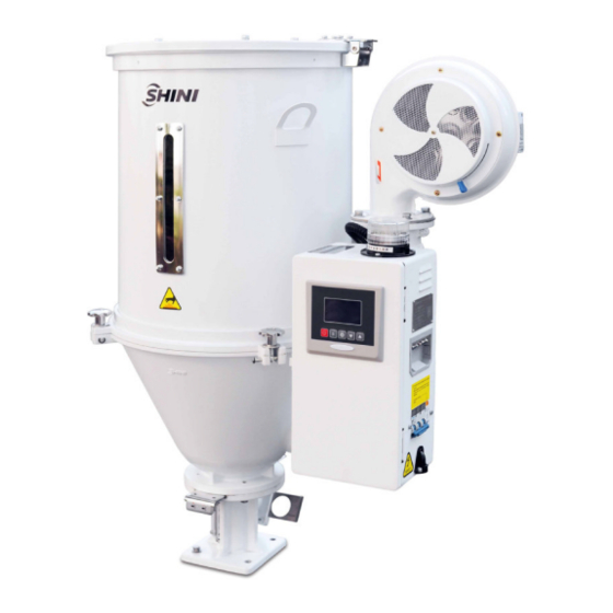
General Description Please read through this operation manual before using the machine to prevent damages of the machine or personal injuries. Picture 1‑1:SHD-50E 6(29) -
Page 7: Coding Principle
1.1 Coding Principle 1.1 Feature Adopt hot air diffuser to keep plastics dry and temperature stable, thus improve drying efficiency. All material contact surfaces are made of stainless steel to eliminate material contamination. All models are equipped with externl power switch. ... - Page 8 Chapter 5, which contains service instructions intended for service engineers. Other chapters contain instructions for the daily operator. Any modifications of the machine must be approved by SHINI in order to avoid personal injury and damage to machine. We shall not be liable for any damage caused by unauthorized change of the machine.
- Page 9 Table 1‑1:Dryer drying capacity(kg/hr)(Selection guide) Notes:Based on relative humidity 65% with ambient temperature of 20℃,moisure content after drying can be 0.2% ro less. 9(29)
-
Page 10: Safety Regulations
1.2 Safety Regulations Note: Electrical installation should be done by qualified electrician only. Before connecting to AC Power Source, turn power switch to OFF position. While AC power source is connected, make sure specifications and overload protection rating of the power switch are suitable and reliable. When the machine is under care or maintenance, turn off both power switch and automatic operation switch. -
Page 11: Sign And Labels
Shini (including employees and agents). Shini is exempted from liability for any costs, fees, claims and losses caused by reasons below: 1. Any careless or man-made installations, operation and maintenances upon machines without referring to the Manual prior to machine using. -
Page 12: Structure Characteristics And Working Principle
In the drying process, hot air with constant temperature is blown by the drying blower of SHD-E. After drying, moisture will be separated out and taken away by hot air, thus to gain a satisfied drying effect. Air blown out of blower via pipe heater became high temperature drying air after being heated. -
Page 13: Options(Purchased Separately
2.2 Options(Purchased Separately) 2.2.1 Magnetic Base Table 2‑1:Configuration Table Model Applied to MB-12EB SHD-12E MB-50 SHD-25E~75E MB-100EB SHD-100E~150E MB-200EB SHD-200E~300E MB-400EB SHD-400E Made of aluminum with built-in hopper magnet, can effectively separate metal scraps out to avoid material contamination and protect the screw. 2.2.2 Hot Air Recycler Table 2‑2:Configuration Table Filtering... -
Page 14: Air Filter
2.2.3 Air Filter Table 2‑3:Configuration Table Model Applied to ADC-1 SHD-12E ADC-2 SHD-25E~150E ADC-3EB SHD-200E ~400E Effectively filter 99% of dust-contain air discharged from dryer to avoid air pollution. 2.2.4 Blower Inlet Filter Table 2‑4:Configuration Table Filtering Overall height Model Barrel Dia. -
Page 15: European Suction Box/Shut-Off Suction Box
2.2.6 European Suction Box/Shut-off Suction Box Applied SHD-12E~75E SHD-100E~400E Model -20-38S -160-38S -20-50S -160-50S -20-38D -160-38D -20-50D -160-50D Notes:1) Install penumatic shut-off valve (Add “V” at the end of the model code.) 2) Change into stainless steel material (Add “S” at the end of the model code.) 3) Stainless steel polishing (Add “P”... - Page 16 SHD-E series. 16(29)
-
Page 17: Installation And Debugging
3. Installation and Debugging Notes for Installation and Positioning: 1) Machine just can be mounted in vertical position. Make sure there’s no pipe, fixed structure or other objects above the installing location and around the machine which may block machine’s installation, hit objects or injure human person. -
Page 18: Power Connection
3.2 Power Connection Make sure the voltage and frequency of the power source comply with those indicated on the manufacturer nameplate that attached to the machine. Power cable and earth connection should conform to your local regulations. Use independent electrical wires and power switch. Diameter of electrical wire should not be less than those used in the control box. -
Page 19: Installation Of The Options
Picture 3‑2:Blower 3.4 Installation of the Options 3.4.1 Installation of Air-Exhaust Filter If the materials contain dust or to avoid the dust-contain air exhausted by dryer polluting the workshop’s environment. Option with air-exhaust filter ADC can filter the exhausted air from the dryer. ADC can reach filter efficiency of 99%. ADC is installed on air-exhaust elbow of the dryer. -
Page 20: Blower Inlet Filter Installation
Picture 3‑4:European suction box When SHD-E is mounted on the floor stand, suction box should be equipped, so as to convey the dried plastic material conveniently. The installation of European suction box and shut-off suction box is simple. Install them at bottom of the hopper, point to the holes and tighten up the screws. -
Page 21: Hot Air Recycler Installation
Installing AIF at blower inlet port when installing it, firstly loosen screws of the blower inlet screen, take down the screen; Then install the AIF at blower inlet port, point to the holes and tighten up the screws. 3.4.4 Hot Air Recycler Installation Based on AIF blower inlet filter, using a hear-resistance pipe to connect the hopper exhausting air to AIF. -
Page 22: Operation Guide
4. Operation Guide 4.1 Control Panel Picture 4‑1:Control Panel 4.1.1 Panel Operation 1) Turn on main switch of control box. 2) Press “ON/OFF”key, it starts drying process, indicator turns green. 3) Press “ON/OFF” key again, it stops drying process, indicator turns yellow. 4.1.2 Temperature Setting 1) The setup number will flicker after pressing "Setting"... -
Page 23: Pid Setting
5) Press “Menu” key to return operation menu. Notes: When “LOCK” is set as “YES, temperature setting value will be locked which not accessible to change. 4.1.4 PID Setting 1) Press both “Menu” and “Down” keys for 3 seconds, it shows “P” (proportion) setting;... -
Page 24: Intermittent Operation Setting
Table 4‑1:PID Setting Parameter Parameters Codes Factory Default Proportion Integral time Integral time 15 ℃ Over-temp alarm Control cycle HCLE Blower delay FDLY ℃ Temp. unit UNIT 4.1.5 Intermittent Operation Setting 1) Hold “Menu” for about 2 secs. to set current time and week. Press “Up” or “Down”... - Page 25 4) Press “Setup” key, the set value flickers, then press “Up”or “Down” key to add or decrease the value. 5) Press “Setting”key to confirm the input value; 6) Press “Up” key again and again, it displays “Baud” and “PAR” settings, (as below ) 7) Repeat step 3 and step 4, then confirm the related input parameters.
-
Page 26: Operation Flow
4.1.8 Operation Flow Rang:0-200℃ 100C 100C Default:90 ℃ ▽ M+5S M+△+3S M+2S M+7S OFF1 ON 1 TIME Heating ratio Communiation Mon. start time Mon. off time Current Rang:1-100℃ 00:00=OFF protocol 00:00=OFF Default:40 ℃ Time(hr,min) Rang: △/ ▽ MODBUS-RTU △/ ▽ △/ ▽... -
Page 27: Wrong Codes Remark
4.1.9 Wrong Codes Remark Table 4‑3:Error Code Description Wrong Codes Remark Thermocouple break Overheat Temperature sensor reversely connected Overload Battery error EGO Over-temp xATx Auto-turning error Low temperature Heating alarm 27(29) -
Page 28: Maintenance And Repair
5. Maintenance and Repair 5.1 Blower 1) Clean the blower regularly (especially the air inlet path) to remove the dust on surface. 2) Eliminate the blower's dirt regularly to avoid the blower damage. Note: No need for regular inspection because all the electrical parts in the control unit are fixed tightly! 28(29) -
Page 29: Troubleshooting
6. Troubleshooting Table 6‑1:Common Faults and Troubleshootings Fault Possible Reasons Solution Exchange two of theel ectrical Blower rotating on the Blower circuit connection reverse phase. contrary with arrow wires. 1 .Motor fault. 1. Check and change. Blower not turning 2. Failures of solenoid switch. 2.
Need help?
Do you have a question about the SHD-E and is the answer not in the manual?
Questions and answers