Table of Contents
Advertisement
Advertisement
Table of Contents

Related Manuals for Shini SHD Series


Summary of Contents for Shini SHD Series
- Page 1 “Standard” Hopper Dryer Date: Dec, 2018 Version: Ver.E...
-
Page 3: Table Of Contents
Content General Description ..................5 1.1 Coding Principle ..................6 1.2 Feature ....................6 1.3 Technical Specifications ................8 1.3.1 External Dimensions ..............8 1.3.2 Specification .................. 9 1.4 Safety Regulations ................11 1.4.1 Safety Signs and Labels .............. 11 1.4.2 Signs and Labels ................. - Page 4 4.1 Control Panel ..................22 4.1.1 Panel Operation ................22 4.1.2 Temperature Setting ..............22 4.1.3 Temperature Lock ............... 22 4.1.4 PID Setting .................. 23 4.1.5 Intermittent Operation Setting ............24 4.1.6 One-week Timing Setting ............24 4.1.7 Communication Setting (optional functions) ........ 24 4.1.8 Operation Flow ................
-
Page 5: General Description
1. General Description Please read through this operation manual before using the machine to prevent damages of the machine or personal injuries. SHD-50 5(28) -
Page 6: Coding Principle
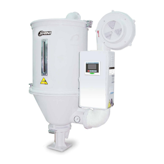
1.1 Coding Principle SHD - xxx - xxx Option Hopper Capacity (kg) "Standard" Hopper Dryer 1.2 Feature l Adopt hot air diffuser to gain an even hot air flow to improve drying efficiency. l Hot air inlet elbow design can prevent dust piling up at bottom of the pipe heaters so as to avoid burning. - Page 7 Chapter 5, which contains service instructions intended for service engineers. Other chapters contain instructions for the daily operator. Any modifications of the machine must be approved by SHINI in order to avoid personal injury and damage to machine. We shall not be liable for any damage caused by unauthorized change of the machine.
-
Page 8: Technical Specifications
1.3 Technical Specifications 1.3.1 External Dimensions SHD-12 SHD-25~150 SHD-200~600 SHD-800/1000 Picture 1-1: External dimensions 8(28) -
Page 9: Specification
1.3.2 Specification Table 1-1: Specification SHD- 1000 Ver. Heater Power 19.2 (kW) / 3* / 3.3* / 4.2* / 4.8* / 6.6* / 7.2* / 9.6* Blower Power 0.05 0.12 0.12 0.12 0.12 0.12 0.18 0.18 0.55 0.55 0.55 (kW) Loading 1000 Capacity (kg) - Page 10 Table 1-2: Dryer drying capacity(kg/hr)(Selection guide) Notes:Based on relative humidity 65% with ambient temperature of 20℃,moisure content after drying can be 0.2% ro less. 10(28)
-
Page 11: Safety Regulations
1.4 Safety Regulations 1.4.1 Safety Signs and Labels Note! Electrical installation should be done by qualified electrician only. Before connecting to AC Power Source, turn power switch to OFF position. While AC power source is connected, make sure specifications and overload protection rating of the power switch are suitable and reliable. -
Page 12: Signs And Labels
The following statements clarify the responsibilities and regulations born by any buyer or user who purchases products and accessories from Shini (including employees and agents). Shini is exempted from liability for any costs, fees, claims and losses caused by reasons below: 1. Any careless or man-made installations, operation and maintenances upon machines without referring to the Manual prior to machine using. -
Page 13: Structure Characteristics And Working Principle
2. Structure Characteristics and Working Principle Working Principle Picture 2-1: Working principle In the drying process, hot air with constant temperature is blown by the drying blower 2 of SHD into the drying hopper 7 to dry the materials. Moisture will be separated out and taken away by hot air, thus to gain a satisfied drying effect. -
Page 14: Options
2.2 Options 2.2.1 Air Filter Model Applied to ADC-1 SHD-12 ADC-2 SHD-25~150 ADC-3 SHD-200~1000 Effectively filter 99% of dust-contain air discharged from dryer to avoid air pollution. 2.2.2 Blower Inlet Filter Model Applied to AIF-12 SHD-12 AIF-25 SHD-25 AIF-50 SHD-50/75 AIF-100 SHD-100/150 AIF-200... -
Page 15: Hot Air Recycler
2.2.4 Hot Air Recycler Filtering Inlet Air Flange of Model Barrel Pipe Dia. Air Outlet Applied to Dia. (mm) (inch) (inch) HAR-12 SHD-12 HAR-25 SHD-15 HAR-50 SHD-50/75 HAR-100 SHD-100/150 HAR-200 SHD-200~500 HAR-600 SHD-600 HAR-800 SHD-800~1000 Work with hopper dryer to make the hot air form a semi-closed circulated loop and has features as follows:... -
Page 16: Material Suction Box/Shut-Off Suction Box
2.2.6 Material Suction Box/Shut-off Suction Box European style in appearance design, work with dryer that has a floor stand and vacuum loader, suitable for material suction and discharging. Applied to SHD-12~75 SHD-100 and above Model -20-38S -160-38S -20-50S -160-50S -20-38D -160-38D -20-50D -160-50D... -
Page 17: Installation And Debugging
3. Installation and Debugging Notes for Installation and Positioning: 1) Machine just can be mounted in vertical position. Make sure there’s no pipe, fixed structure or other objects above the installing location and around the machine which may block machine’s installation, hit objects or injure human person. -
Page 18: Floor Stand Installation
3.2 Floor Stand Installation Picture 3-2: Floor stand installation Floor stand installation type is to mount dryer on a floor stand, then via a photo-sensor hopper receiver to convey the material to the feed port of a molding machine. SHD-400 and above models should adopt floor stand installation type. Machine should be placed on water-level floor to keep balance. -
Page 19: Installation Of The Options
Picture 3-3: Blower 3.5 Installation of the Options 3.5.1 Installation of Air-Exhaust Filter If the materials contain dust or to avoid the dust-contain air exhausted by dryer polluting the workshop’s environment. Option with air-exhaust filter ADC can filter the exhausted air from the dryer. ADC can reach filter efficiency of 99%. ADC is installed on air-exhaust elbow of the dryer. -
Page 20: Blower Inlet Filter Installation
When SHD is mounted on the floor stand suction box should be equipped. To convey the dried plastic material conveniently. The installation of suction box is simple. Install them at bottom of the hopper, point to the holes and tighten up the screws. -
Page 21: Picture 3-8: Hot Air Recycler
Picture 3-8: Hot air recycler 21(28) -
Page 22: Operation Guide
4. Operation Guide 4.1 Control Panel Picture 4-1: Control Panel 4.1.1 Panel Operation 1) Turn on main switch of control box. 2) Press “ON/OFF” key, it starts drying process, indicator turns green; 3) Press “ON/OFF” key again, it stops drying process, indicator turns yellow. 4.1.2 Temperature Setting 1) The setup number will flicker after pressing "Meun"... -
Page 23: Pid Setting
4.1.4 PID Setting 1) Press both “Menu” and “Down” keys for 3 seconds, it shows “P” (proportion) setting; 2) Press “Setup” key, the set value flickers, then press “Up”or “Down” key to add or decrease the value. 3) Press “Setup” key to confirm the input value. 4) Press “Up”... -
Page 24: Intermittent Operation Setting
4.1.5 Intermittent Operation Setting Hold “Menu” for about 2 secs. to set current time and week. Press “Up” or “Down” key to set start/stop function of AUTO timer, the time for RONE intermittent operation, the OFF time of ROFF intermittent operation, the ON time of RON intermittent operation. - Page 25 Communication Parameters Communication Codes Factory Default Communication Protocol Communication Address 1(current address) Baud Rate Baud 19.2K none Data Length Data Stop Bit Stop 25(28)
-
Page 26: Operation Flow
4.1.8 Operation Flow Rang:0-200℃ 100C 100C Default:90 ℃ ▽ M+5S M+△+3S M+2S M+7S OFF1 ON 1 TIME Heating ratio Communiation Mon. start time Mon. off time Current Rang:1-100℃ 00:00=OFF protocol 00:00=OFF Default:40 ℃ Time(hr,min) Rang: MODBUS-RTU △/ ▽ △/ ▽ △/ ▽... -
Page 27: Wrong Codes Remark
4.1.9 Wrong Codes Remark Wrong Codes Remark Thermocouple break Overheat Temperature sensor reversely connected Overload Battery error EGO Over-temp xATx Auto-turning error 27(28) -
Page 28: Maintenance And Repair
5. Maintenance and Repair 5.1 Blower 1) Clean the blower regularly (especially the air inlet path). 2) Eliminate the fan's dirt regularly to avoid the damage to the blower. Note: No need for regular inspection because all the electrical parts in the control unit are fixed tightly! 6.
Need help?
Do you have a question about the SHD Series and is the answer not in the manual?
Questions and answers