
Related Manuals for Delixi CDM3LS Series


Summary of Contents for Delixi CDM3LS Series
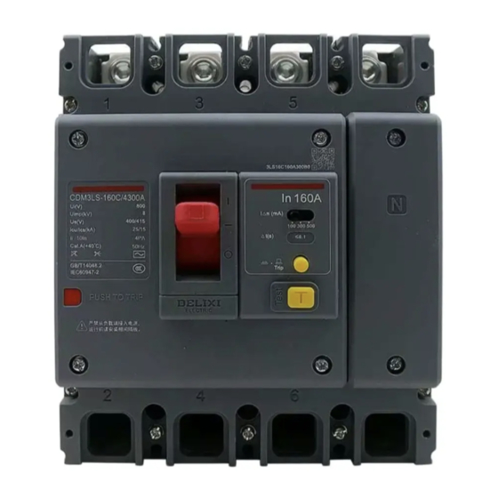
- Page 1 NAVIGATOR CDM3LS Series RESIDUAL CURRENT OPERTED Series CIRCUIT-BRAKER User Manual Standard: GB/T 14048.2 IEC 60947-2 □Please carefully read this manual before the installation and operation of this product, and keep it properly for future reference.
-
Page 2: Safety Notice
Safety Notice Please carefully read this manual before the installation, operation, run, maintenance, and inspection of the product, and install and operate this product properly according to the contents of the instructions. Danger: It is prohibited to operate the switch disconnector with your wet hands; ... - Page 3 When scrapping the product, please dispose the product waste properly; thanks for your cooperation. Test: This circuit breaker has passed the insulation test specified by the standard in the factory. For electric leakage product, it is not recommended to conduct the retest of insulation. If retest is required before installation, please disconnect the electronic elements between the current circuits, otherwise this may cause damage to the product performance.
- Page 4 1.2 Product Working Environment and Conditions The protection grade of this product is IP30 (terminal block position: IP00) The pollution level of this product is Level 3 The rated operating voltage is 400/415V (2P:AC230V0) The altitude at the installation side shall not exceed 2000m. If the installation site has an altitude of more than ...
- Page 5 3 Outline, Installation and Wiring Dimensions of CDM3LS Series X-X: Center axis of base, the same below Y-Y: Center axis of handle, the same below Insert here on the upper cover in the arrow direction marked on the flash barrier...
- Page 6 Unit: mm Product Outline dimensions Installation dimensions Number model of poles Φd CDM3LS- 125 S 24.5 125 S/F 23.5 98.5 93.5 28.5 160/250 S 50.5 73.5 26.5 126.3 21.5 12.5 160/250 63.5 83.5 12.5 400 F/N 98.5 112.5 107.5 37.5 36.5 630/800 123.5...
- Page 7 Caution: When the circuit breakers are installed in parallel, the insulation safety between the terminals must be ensured. It is recommended to install a long terminal cover or use an additional phase partition to provide the insulation protection between two products; If more compact installation is required, a zero flashover hood is recommended to obtain a smaller safety distance;...
- Page 8 4.3 Size of Hole on Mounting Plate Unit: mm Product model Number of poles ΦD CDM3LS- 125 S 125 S/F 160/250 S 126.3 160/250 S/F 400 F/N 630/800 F/N...
- Page 9 Recommended sectional area of copper busbar (mm Caution: Please follow the dimensions C, C1, and C2 in the outline, installation and wiring dimensions of CDM3LS series and the diameter of the corresponding wiring screw, and select an appropriate terminal block or busbar to meet the corresponding wiring capacity requirements.
- Page 10 5 Internal Accessories and Expansion Function (not available for 2P product) 5.1 Internal accessories (undervoltage release, shunt release, auxiliary, alarm, dual auxiliary, and auxiliary alarm) Assembly Diagram Operation step Operation step Operation step 1 Loosen the screws and remove the cover 1 1 Install the left accessory 2 1 Install the cover 1, tighten the screws 2 Remove the left plug 2 if any...
- Page 11 Electrical Parameters Undervoltage coil holding power consumption (W) Undervoltage coil suction min. power (W) Product model CDM3LS- AC400V AC230V AC400V AC230V 125 S/F 0.44 0.44 Suction assist type Suction assist type 160/250 S/F Suction assist type Suction assist type 400/630/800 F/N 0.77 0.75...
- Page 12 Test Requirements for Internal Accessories Undervoltage release: 1.1) At the 35%~70% rated operating voltage, the undervoltage release can trip the circuit breaker; 1.2) At the 85%~110% rated operating voltage, the undervoltage release can power on the circuit breaker reliably; 1.3) When the rated operating voltage is below 35%, the undervoltage release can prevent the circuit breaker from power-on;...
- Page 13 3. The power-on duration time of the shunt release shall not exceed 5s, otherwise the shunt release will burn. When the selected rated control power voltage is DC24V, the rated current of control circuit shall reach 4.5A~5.5A. 4. The undervoltage accessory is of the backpack structure when delivery, and all accessories are of the wire lead structure by default except for undervoltage accessory.
-
Page 14: Maintenance And Service
Leakage alarm module wiring diagram and working schematic diagram 6 Maintenance and Service The maintenance and service must be conducted by the qualified professionals Make sure that the product is deenergized; The maintenance and service shall be conducted once yearly under the normal operating conditions, and the ... - Page 15 8 Company’s commitment Under the premise that users follow the use and storage conditions and the product are well sealed, within 36 months from the production date, our company will provide repair and replacement service free of charge for any damage or abnormal operation due to poor manufacture quality.
- Page 16 Inspector: Check 01 Date of production: See label on inner box For more information, please follow WeChat official account! Address: Delixi High-Tech Industrial Park, Liushi Town, Yueqing City, Zhejiang P.C: 325604 Tel: (86-577) 6177 8888 Fax: (86-577) 6177 8000 Service hotline: 400-826-8008 www.delixi-electric.com...
Need help?
Do you have a question about the CDM3LS Series and is the answer not in the manual?
Questions and answers