Table of Contents
Advertisement
Advertisement
Chapters
Table of Contents

Related Manuals for Delixi CDW3 Series


Summary of Contents for Delixi CDW3 Series
- Page 1 CDW3 series Air Circuit Breaker User's Manual...
- Page 2 Make sure the end user has this user manual. Read and strictly abide this use manual before use. Sign Delixi provide “three guarantee service”within 36 months warranty from manufacture date for the manufacture defect under normal storage, maintenance and storage condition.
-
Page 3: Table Of Contents
CONTENT 1 About CDW3 Secondary circuit wiring diagram 29-30 Open 4 Debugging CDW3 About breaker Know the nameplate iTR326 series electronic trip unit 31-34 Size and weight Protection characteristics general) 35-36 Breaker structure Menu Debugging operation iTR326A operation 38-39 iTR326H operation 40-41 2 Carry CDW3 5 Functions... -
Page 4: About Cdw3
About CDW3 Open Wooden box CDW3 Screw Power Doorframe Interphase User's converter partition Manual About breaker Draw-out Fixed Know the nameplate Please read the nameplate and data plate information carefully before installation Rated current Applicability (quarantine) Rated insulation voltage date of manufacture Rated impulse withstand Rated voltage voltage... -
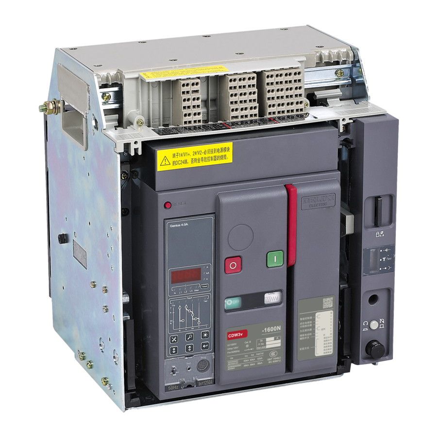
Page 5: Breaker Structure
About CDW3 Breaker structure Drawer seat (schematic diagram, subject to the configuration table) Padlock lock handle Rocker storage Bundle collet Separation, test connection Rocker Handling handle position indication Rocker socket Pull out the handle Arc chute cover Three position locking device Door interlock unlocking button... -
Page 6: Debugging Operation
About CDW3 Debugging operation Reset button Energy storage handle Opening button Closing button Window(O/I) Window(Reday) Separation, test and connection position indication Three position locking device unlocking button Rocker storage Rocker Opening and closing operation of circuit breaker If there is undervoltage release, it must be powered first First watch the indication window to determine whether the circuit breaker is in the opening state. -
Page 7: Carry Cdw3
Carry CDW3 Carry requirement Severe collision shall be avoided as far as possible Do not reverse or roll the circuit breaker Handle with care Heavy bus terminal of circuit breaker Please carry it as shown in the right figure Transportation environment temperature: - 25 ℃ ~ 55 ℃, relative humidity: no more than 90% (at 25 ℃) Carry way When carrying the drawer type circuit breaker body together,... -
Page 8: Installation Cdw3
Installation CDW3 Tool Screwdriver(-) Screwdriver(+) Screwdriver(+) Wrench Installation requirements The installation position shall be vertical, and the inclination in each direction shall not exceed 5 ° The main circuit, undervoltage release and primary coil of power transformer of the circuit breaker are class IV, and the auxiliary circuit and control circuit are class III Installation way 2. - Page 9 Installation CDW3 3. Bus installation Drawer type, fixed type is the same Note: vertical wiring is limited to 1600AF/4000AF 4. Safe distance Safe distance Draw-out Fixed (mm) Insulation Metal Live conductor...
-
Page 10: Recommend Size Of User Busbar
Installation CDW3 Recommend Size of user busbar Reference table of wiring busbar specifications under different temperatures Allowable maximum temperature of busbar: 100 ℃ Busbar material is bare copper Ambient temperature +40℃ Ambient temperature +50℃ Ambient temperature +60℃ Rated Frame current 5mm busbar 10mm busbar 5mm busbar... -
Page 11: Size For 1600N&H
Installation CDW3 Size for 1600N&H 1600N&H Draw-out 3P&4P Datum point Horizontal fixation (on base plate or track) Vertical fixation (on backplane or rack) Safe spacing Door opening size Rear panel opening size Safe distance Draw-out (mm) Insulation Metal Live conductor Note 1: the schematic diagram of safety distance is schematic diagram, and the circuit breaker shall be subject to the real object Note 2: the x-axis and Y-axis of the 3-pole circuit breaker are symmetrical to the front cover of the circuit breaker body... - Page 12 Installation CDW3 1600N&H Draw-out back connection Datum point Horizontal back connection Vertical back connection Rear connection with extension terminal Refer to "rear connection with extension terminal" for installation 1.4-pole center left or right extension terminal 2.3-pole intermediate expansion terminal 3.4-pole left or right extension terminal 4.3-pole left or right extension terminal Note: the x-axis and Y-axis of the 3-pole circuit breaker are symmetrical to the front cover of the circuit breaker body...
- Page 13 Installation CDW3 1600N&H Fixed 3P&4P Datum point Horizontal fixation (on base plate or track) Vertical fixation (on backplane or rack) Safe spacing Door opening size Rear panel opening size Fixed Safe distance (mm) Insulation Metal Live conductor Note 1: the schematic diagram of safety distance is schematic diagram, and the circuit breaker shall be subject to the real object Note 2: the x-axis and Y-axis of the 3-pole circuit breaker are symmetrical to the front cover of the circuit breaker body Note 3: (*) the safety distance shall be considered to be 50mm when removing the arc extinguishing cover and 20mm when removing the terminal block...
- Page 14 Installation CDW3 1600N&H Fixed back connection Datum point Horizontal back connection Vertical back connection Rear connection with extension terminal Refer to "rear connection with extension terminal" for installation 1.4-pole center left or right extension terminal 2.3-pole intermediate expansion terminal 3.4-pole left or right extension terminal 4.3-pole left or right extension terminal Note: the x-axis and Y-axis of the 3-pole circuit breaker are symmetrical to the front cover of the circuit breaker body...
-
Page 15: Size For 2000N&H
Installation CDW3 Size for 2000N&H 2000N&H Draw-out 3P&4P Fixed horizontally (on the base plate or track) * the distance of the mask protruding from the door frame is 5mm Safe spacing Door opening size Bus size Safe distance Draw-out (mm) In(A)... - Page 16 Installation CDW3 2000N&H Fixed 3P&4P Fixed horizontally (on the base plate or track) * the distance of the mask protruding from the door frame is 5mm Safe spacing Door opening size Bus size Fixed Safe distance (mm) In(A) a(mm) Insulation 630-800 Metal 1000-1600...
-
Page 17: Size For 500N&H
Installation CDW3 Size for 2500N&H 2500N&H Draw-out 3P&4P Fixed horizontally (on the base plate or track) * the distance of the mask protruding from the door frame is 5mm Safe spacing Door opening size Bus size Safe distance Draw-out (mm) In(A)... - Page 18 Installation CDW3 2500N&H Fixed 3P&4P Fixed horizontally (on the base plate or track) * the distance of the mask protruding from the door frame is 5mm Safe spacing Door opening size Bus size Safe distance Fixed (mm) In(A) a(mm) Insulation 630-2000 Metal Live conductor...
-
Page 19: Size For 3200N&H
Installation CDW3 Size for 3200N&H 3200N&H Draw-out 3P&4P Fixed horizontally (on the base plate or track) * the distance of the mask protruding from the door frame is 5mm Safe spacing Door opening size Bus size Safe distance Draw-out (mm) In(A)... -
Page 20: (Mm) Ab
Installation CDW3 3200N&H Fixed 3P&4P Fixed horizontally (on the base plate or track) * the distance of the mask protruding from the door frame is 5mm Safe spacing Door opening size Bus size Safe distance Fixed (mm) In(A) a(mm) Insulation 2000-2500 Metal 3200... -
Page 21: Size For 4000N&H
Installation CDW3 Size for 4000N&H 4000N&H Draw-out 3P&4P Datum point Horizontal fixation (on base plate or track) Door opening size Safe spacing Draw-out Safe distance (mm) Insulation Metal Live conductor Note 1: the schematic diagram of safety distance is schematic diagram, and the circuit breaker shall be subject to the real object Note 2: the x-axis and Y-axis of the 3-pole circuit breaker are symmetrical to the front cover of the circuit breaker body... - Page 22 Installation CDW3 4000N&H Draw-out back connection Datum point 630A-3200A Horizontal back connection Vertical back connection 4000A Horizontal back connection Vertical back connection Note : the x-axis and Y-axis of the 3-pole circuit breaker are symmetrical to the front cover of the circuit breaker body...
- Page 23 Installation CDW3 4000N&H Fixed 3P&4P Datum point Horizontal fixation (on base plate or track) Safe spacing Door opening size Safe distance Fixed (mm) Insulation Metal Live conductor Note 1: the schematic diagram of safety distance is schematic diagram, and the circuit breaker shall be subject to the real object Note 2: the x-axis and Y-axis of the 3-pole circuit breaker are symmetrical to the front cover of the circuit breaker body Note 3: (*) the safety distance shall be considered to be 50mm when removing the arc extinguishing cover and 20mm when removing the terminal block...
- Page 24 Installation CDW3 4000N&H Fixed back connection Datum point 630A-3200A Horizontal back connection Vertical back connection 4000A Horizontal back connection Vertical back connection Note : the x-axis and Y-axis of the 3-pole circuit breaker are symmetrical to the front cover of the circuit breaker body...
-
Page 25: Size For 6300N
Installation CDW3 Size for 6300N 6300N Draw-out 3P&4P Datum point Fixed horizontally (on the base plate or track) * the distance of the mask protruding from the door frame is 5mm Safe spacing Door opening size Safe distance Draw-out (mm) Insulation Metal Live conductor... -
Page 26: In(A) A(Mm
Installation CDW3 4000N Draw-out back connection Datum point 4000A-6300A Horizontal back connection In=4000A/5000A In=6300A In(A) a(mm) 4000 5000 6300 Note: the x-axis and Y-axis of the 3-pole circuit breaker are symmetrical to the front cover of the circuit breaker body... -
Page 27: Accessory Installation
Installation CDW3 Accessory installation Danger: power must be cut off before installation!!! The drawer type must have the circuit breaker in the off position Circuit breaker accessories (the figure below is only a schematic diagram, subject to the actual object) Open the mask and remove the secondary terminal Install undervoltage release, shunt release, closing electromagnet, auxiliary contact, electric operating mechanism... - Page 28 Installation CDW3 Installing the secondary circuit 1)1600N&H Draw-out 1. Fix the lower end of the secondary terminal first 2. Insert the upper end of the secondary wiring terminal into the groove of the secondary wiring terminal box, and hear the "click" sound, indicating that the secondary wiring terminal is fixed Fixed 1.
- Page 29 For the installation dimension of transformer, please refer to the dimension page of accessories Note: for the installation of cable interlocking and lever interlocking, please refer to the website( www.delixi-electric.com ) Product center > power distribution > ACB > CDW3...
-
Page 30: Accessory Size
Installation CDW3 Accessory size N-phase external transformer 1)1600N&H 2)2000N&H 3)2500N&H 3200N&H 4)4000N&H 5)6300N Note: if the width of the customer's wiring bank is larger than the installation hole of the n-phase external transformer, the customer is requested to process a section of the bank through the transformer according to the width of the transformer. - Page 31 Installation CDW3 Leakage transformer Grounded current transformer Note: the overall dimensions of 4000A, 5000A and 6300A are the same as that of leakage transformer Power converter Signal conversion module...
-
Page 32: Secondary Circuit Wiring Diagram
Installation CDW3 Secondary circuit wiring diagram... - Page 33 Installation CDW3...
-
Page 34: Debugging Cdw3
Debugging CDW3 iTR326 Series Electronic trip unit Appearance and function Type iTR326(L) iTR326A(M) iTR326H(H) Protection function Long time delay protection L Long time delay protection L Long time delay protection L Short time delay protection S Short time delay protection S Short time delay protection S Instantaneous protection Instantaneous protection... - Page 35 Debugging CDW3 Description of indicator light and key -iTR326 iTR326 Signal indication Panel operation instructions Basic type(L) Alarm indication Reset button Long time delay trip Multiple setting of long time indication delay current IR Short time delay or Long delay time setting tR instantaneous trip indication Earth or leakage fault trip Padlock position...
- Page 36 Debugging CDW3 Description of indicator light and key -iTR326A iTR326A Signal indication Standard type(M) N-phase current Long time delay protection indication A-phase current Short time delay protection indication B-phase current Test action status C-phase current Instantaneous protection indication Maximum current Multiple setting of long time delay current IR Current unit A...
- Page 37 Debugging CDW3 Description of indicator light and key -iTR326H iTR326H Signal indication Advanced type(H) Alarm indication Non high and low Long time delay trip indication temperature type Short time delay or instantaneous trip indication Earth or leakage fault trip indication Advanced protection Communication function Panel operation instructions...
-
Page 38: Protection Characteristics(General)
Debugging CDW3 Protection characteristics(general) Protection characteristics of Electronic trip unit The protection features of the intelligent controller include inverse time limit and timing limit. When the fault current exceeds the inverse time limit setting value, the controller sets the time delay protection according to the fixed time limit Inverse time curve conforms to characteristic curve I Overload long time delay protection characteristics... - Page 39 Note: the grounding fault protection of 3p product is in off state (off gear) from the factory, which can be adjusted by the user according to the actual situation. Note: refer to the website for instructions of iTR326 series Electronic trip unit( www.delixi- electric.com )
-
Page 40: Menu
Debugging CDW3 Menu iTR326 In case of failure, reset; in case of non failure, long press to Reset key check the last failure Test button, momentary action Test key iTR326A For power meter display parameter switching Select key Used to enter parameter setting mode Set key Used to view fault record information Query key... -
Page 41: Itr326A Operation
Debugging CDW3 iTR326A operation operation display The ETU needs to display various operation parameters, setting parameters and other values on the panel Use LED digital tube to display the value, and use LED indicator to indicate the type of value displayed ammeter maximum current display ... - Page 42 Debugging CDW3 iTR326A User set parameters parameter LED indicator remarks Setting of grounding protection current LED_lg、LED_A Time setting of grounding protection LED_Tg、LED_s Current setting of long time delay protection LED_I 、LED_A Long time delay protection time setting LED_T 、LED_s Short time delay protection current setting LED_Isd、LED_A/LED_kA Setting of short delay protection time...
-
Page 43: Itr326H Operation
Debugging CDW3 iTR326H operation default interface Display the default interface when the ETU is powered on press the button or the corresponding topic key under each topic menu to return to the default interface If there is no key operation within 5 minutes, the box cursor will automatically ... - Page 44 Debugging CDW3 Protection parameter setting menu Press to return to the default interface In other non fault and non edit interfaces, press to jump to "protection parameter setting" menu history and maintenance menu Press to return to the default interface In other non fault and non edit interfaces, press to jump to "system parameter setting"...
-
Page 45: Functions
Functions Technical parameter common characteristic poles 3、4 Rated working voltage Ue 1: AC220V/230V/240V/380V/400V/415V 2: AC440V/480V/500V/525V/550V/660V/690V Rated insulation voltage Ui 1000V Rated impulse withstand 12kV voltage Uimp Rated frequency Hz 50/60 Suitable for isolation Applicable standards GB/T14048.2、IEC 60947-2 Current/Frame 1600N 1600H 2000N 2000H 2500N... - Page 46 Note: if the altitude is higher than 4000m, it is necessary to contact with the factory. ①: 1600n & H is 0.8 ╳ in, 3200n & H is 0.7 ╳ in. For details, communicate with Delixi Electrical Technology Department Note: in the plateau environment, the breaking capacity shall be reduced according to the corresponding rated working voltage, generally between 75% and 50%,...
-
Page 47: Know The Accessory
Functions Know the accessory Remote operation: (1600AF/4000AF on the left, 2000AF/2500AF/3200AF/6300AF on the right) Release MX: After the circuit breaker is stored with energy, the shunt coil can disconnect the circuit breaker instantaneously under the specified power supply voltage, which can be operated remotely Rated control power supply voltage AC220 / AC230V / AC380V / AC400V / ... - Page 48 Functions Indicating contact: (1600AF/4000AF on the left, 2000AF/2500AF/3200AF/6300AF on the right) Auxiliary switch OF: It is used to monitor the status of the circuit breaker, such as connecting the position signal light of the circuit breaker, disconnecting the indicator light, etc default 4 on 4 off ...
- Page 49 Functions lock:(1600AF on the left, 2000AF/2500AF/3200AF/4000AF/6300AF on the right) Draw frame padlock: If the padlock is selected, when the circuit breaker is in the "separate" position, pull out the padlock piece. After locking, the rocker cannot be inserted padlock by user Opening lock ...
- Page 50 Functions Protection:(1600AF on the left, 2000AF/2500AF/3200AF/4000AF/6300AF on the right) Door frame: door frame mounted on the door of distribution cabinet IP protection level increased from IP20 to IP40 Drawer type and fixed type are applicable Interphase partition: ...
- Page 51 Functions Controller accessories:(1600AF on the left, 2000AF/2500AF/3200AF/4000AF/6300AF on the right) N-phase external transformer: In the 3P + n grounding mode, the external transformer used to measure the neutral phase current is sheathed on the wiring busbar by the user One out of three with grounding transformer and leakage transformer ...
-
Page 52: Maintenance
Maintenance Working conditions ambient -5 ℃ ~ + 40 ℃, daily average value ≤ 35 ℃ temperature Note: the circuit breaker used when the ambient air temperature is higher than + 40 ℃ or lower than - 5 ℃ shall be negotiated with the manufacturer altitude ≤2000m ambient... -
Page 53: Troubleshooting
Maintenance Troubleshooting Fault phenomenon Cause analysis Exclusion scheme remarks Motor cannot store The voltage specification Check whether the data label on the The external power supply energy or abnormal is inconsistent with the circuit breaker conforms to the must meet the requirements circuit breaker ordering requirements, or it will be and the wiring is correct... -
Page 54: Appendix
Appendix Trip curve Three stage protection Earth protection... -
Page 55: Model Selection Table
Appendix- Model selection table Number __________ Circuit breaker body (required) frame 1600AF □ 2000AF □ 2500AF □ 3200AF □ 4000AF □ 6300AF □ Breaking capacity □ □ Note:6300AF have not H Rated current 400A □ 630A □ 630A □ 2000A □... -
Page 56: Configuration Table
Appendix- Configuration table 1600AF 2000AF 2500AF 3200AF 4000AF 6300AF Standard configuration Draw- Draw- Draw- Draw- Draw- Draw- Fixed Fixed Fixed Fixed Fixed Fixed Circuit breaker body ▄ ▄ ▄ ▄ ▄ ▄ ▄ ▄ ▄ ▄ ▄ Drawer seat ▄ ▄... - Page 57 2020 年 01 月 第一版...
Need help?
Do you have a question about the CDW3 Series and is the answer not in the manual?
Questions and answers
The 2 main breakers are connected to a generator and transformer respectively but we are unable to charge the one connected to the transformer.What could be the problem.
If the Delixi CDW3 Series breaker connected to the transformer is not charging, possible causes include:
1. External Power Supply Issue – The external power supply may not meet the required voltage or may be inconsistent with the circuit breaker specifications.
2. Wrong Wiring – Incorrect wiring of the circuit breaker or external connections. Check the wiring against the wiring diagram using a universal meter.
3. Burnt Motor – If the motor is burned out, it needs to be replaced.
4. Travel Switch Failure – If the motor continues operating after energy storage, the travel switch may be broken and should be replaced.
Check these issues and correct them to restore charging.
This answer is automatically generated