
Related Manuals for Delixi Knight Series


Summary of Contents for Delixi Knight Series
- Page 1 CDC6H-120~630 Knight Series AC CONTACTOR User Manual Please carefully read this User Manual before the installation and operation of this product, and keep it properly for future reference Internal...
- Page 2 CDC6H-120~630 AC Contactor User Manual Safety Notice Please carefully read this manual before the installation, operation, run, maintenance, and inspection of this product, and install and operate this product properly in accordance with the instructions. Danger ● It is prohibited to operate the contactor with your wed hands; ●...
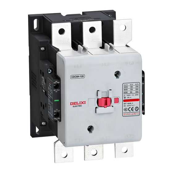
- Page 3 Legends: 1 - Main circuit inlet end 1/L1, 3/L2, 5/L3 7 - Rated operating current, voltage, and power 2 – Product model 8 - Insulation voltage Ui: 1000V 3 - Main circuit outlet end 2/T1, 4/T2, 6/T3 9 - Standard: GB/T14048.4 4 - Normally open auxiliary wiring terminal IEC 60947-4-1 5 - Normally closed auxiliary wiring terminal...
- Page 4 Electrical life x 10 Breaking current Ic (A) Fig. 2: Life curve Normal Operation, Installation, and Transport Conditions ● Normal operation and installation conditions (1) Ambient air temperature: the ultimate working temperature is ranged -35℃~ +70℃, the normal working temperature is -5℃~ +55℃, and the mean value within 24 hours does not exceed +35℃. When the working environment temperature is higher than 55℃, it must be considered that the allowable ultimate temperature rise of the product may be reduced;...
- Page 5 (3) When the maximum temperature is +70℃, the relative humidity of the air does not exceed 50%; higher relative humidity can be allowed at lower temperatures, such as 90% at +20℃, and protective measures should be taken for condensation occasionally occurred due to temperature changes; (4) The installation position should be vertical, and the inclination angle in all directions should not exceed ±...
- Page 6 ● The outline and installation dimensions of the contact are shown in Fig. 4 and Table 4 Fig. 4 Outline and installation dimensions of CDC6H-120~630 product Table 4 Outline and installation dimensions of CDC6H-120~630 AC contactor Unit: mm Model Amax A1max Bmax B1max...
- Page 7 Table 5 Outline and installation dimensions of the CDC6H-120~~630 reversible AC contactor Unit: mm Model Fmax CDC6H-120/160/185/225 241.5 129.5 CDC6H-265/330/400 309.5 CDC6H-500/630 339.5 189.5 ● Accessory installation Dust cover Fig. 6: Accessory installation diagram (1) Auxiliary contact CDC6H-120~630 contactor body is equipped with two sets of one pair of normally open and one pair of normally closed auxiliary contacts as standard configuration, its model is FC4-11, and its main parameters are listed in Table 6;...
- Page 8 The contactors can be equipped with independent auxiliary contact modules, and its model, specifications and normally open and normally closed combination are shown in Table 7. The installation of F4 is consistent with the installation method of the air delay head, and the installation and disassembly of FC4-11 are shown in Fig. 7 and Fig.
- Page 9 Table 8 Air delay head Model & Spec. Delay range Number of delay contacts Delay type FT6-30 0.1~3s FT6-32 0.1~30s 1NO+1NC Power-off delay FT6-34 10~180s Note: The air delay head is adjusted to the minimum value before shipment. The installation and disassembly of the air delay head is shown in Figs. 10 and Fig. 11. ○...
- Page 10 (4) The installation and disassembly method of the coil is shown in Fig. 13 and Fig. 14: Fig. 13 Disassembly method of coil Fig. 14 Installation method of coil (5) Electromagnetic starter The contactor can be combined with JR2H series thermal overload relay to form an electromagnetic starter. Debugging and Operation ●...
- Page 11 Maintenance and Service ● Please tighten the wiring terminal of the contactor and remove the deposited dust regularly, otherwise there will be a risk of fire and short circuit; ● Small metal particles sprayed around the contact of contactor or on the arc hood should be removed, and the contactor shall stop operation when the contact surface is burnt out to expose the base material.
- Page 12 (4) Force majeure such as earthquakes, fires, lightning strikes, abnormal voltages, and secondary disasters. If you have any questions, please contact our dealer or our company’s customer service department. Customer Service Hotline: 400-826-8008 Delixi Industrial Park, Liushi Town, Yueqing City, Zhejiang Province P.C.: 325604 Tel: (86-577) 6177 8888 Fax: (86-577) 6177 8000 Customer Service Hotline: 400-826-8008 www.delixi-electric.com...
Need help?
Do you have a question about the Knight Series and is the answer not in the manual?
Questions and answers