Table of Contents
Advertisement
Quick Links
Advertisement
Table of Contents

Related Manuals for Triplett TEV500


Summary of Contents for Triplett TEV500
- Page 1 TEV500 PRO Electric Vehicle Charger Test Kit...
-
Page 2: Operation Elements And Connectors
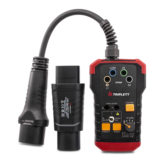
Operation Elements and Connectors 1. Measuring terminals L2 (N), PE 2. Measuring terminals L1, PP 3. Phase indicators LED for L1 4. PE and CP Signal output terminals 5. PE Pre-Test warning light indicator 6. PE Pre-Test touch probe 7. “E” - CP Error simulation button 8. -
Page 3: Table Of Contents
Content Content Operation Elements and Connectors ....10 References ............... 12 Safety References ........... 13 Testing ..............14 PE Pre-Test ............14 Test procedure ..........14 Control Pilot (CP) State (Vehicle Simulation) ..14 CP Signal output terminals ......... 15 ... -
Page 4: References
References References marked on instrument or in instruction manual Warning of a potential danger, follow with instruc- tion manual. Reference! Please use utmost attention. Caution! Dangerous voltage. Danger of electrical shock. Ground terminal Continuous double or reinforced insulation catego- ry II IEC 536 / DIN EN 61140. Conformity symbol, the instrument complies with the valid directives. -
Page 5: Safety References
Safety references Safety references The respective accident prevention regulations established by the professional associations for electrical systems and equipment must be strictly met at all times. In order to avoid electrical shock, the valid safety and VDE regulations regarding excessive contact voltages must receive utmost attention, when work- ing with voltages exceeding 120V (60V) DC or 50V (25V)rms AC. -
Page 6: Testing
Testing Testing of the charging station PE Pre-Test Prior all other tests PE pretest must be successfully carried out. The PE Pre-Test allows the operator to test the PE con- ductor for possible presence of dangerous voltage against earth. Normally the PE conductor is connected to earth and has no voltage against earth. -
Page 7: Cp Signal Output Terminals
Testing CP Signal output terminals CP output terminals are short connected to the CP and PE conductors of the tested charging station via the test cable (no.4 on the picture). Use an oscilloscope to check the waveform and amplitude of the CP signal. Control Pilot function uses Pulse Width Modulation (PWM) to code communication between a vehicle and charging station. -
Page 8: Cleaning
Cleaning / Specifications Cleaning If the instrument is dirty after daily usage, it is advised to clean it by using a humid cloth and a mild household detergent. Prior to cleaning, ensure that instrument is switched off and disconnected from external voltage sup- ply and any other instruments connected (such as UUT, control instruments, etc.).
Need help?
Do you have a question about the TEV500 and is the answer not in the manual?
Questions and answers