Table of Contents
Advertisement
Advertisement
Table of Contents

Related Manuals for Triplett 310


Summary of Contents for Triplett 310
- Page 1 TRIPLETT Model Type 9 310-C Type 9...
-
Page 3: Table Of Contents
SPECIFICATIONS ..........9 GENERAL INSTRUCTIONS ........ 11 Test Leads ..........11 Range Selection ........11 Scale Selection ........12 Polarity Selection (310-C only) ....12 Changing Settings ........12 Zero Adjustment ........12 Other Considerations ........ 13 Care ............ 13 CONTROL LOCATION DIAGRAM ...... -
Page 4: Safety Rules
SAFETY RULE WARNING This tester has been designed with your safety in mind. However, no design can completely protect against in- correct use. Electrical circuits can be dangerous and/ or lethal when lack of caution or poor safety practices are used. WARNING This meter is NOT to be used to measure High Energy circuits (power circuitry fused at greater than 4KW, such... - Page 5 AC (310-C...
- Page 6 Make sure both test leads are fully inserted into their respec- tive input jacks (Black lead into COM and Red lead into ). A loose test lead may cause the user to misinter- pret the dangers present (the meter may read Zero when dangerous voltage is present) or the loose lead may accidentally short to other circuitry or shock the user.
- Page 7 Do not use the meter if it does not appear to work correctly on all ranges and in all modes. Do not use the meter if it has undergone long-term storage under unfavorable conditions. Do not use the meter if it may have been damaged in transport.
- Page 8 Do not mistake a downscale reading as an indication that no potential is present. Dangerous potentials may be present that may result in user injury. When replacing the battery, dispose of the depleted battery in accordance with any prevailing safety or environmental regulations.
- Page 9 DO NOT TOUCH Do not touch exposed wiring, connections or other “live” parts of an electrical circuit. If in doubt, check the circuit first for voltage before touching it. Turn off the power to a circuit before connecting test probes to it. Be sure there is no voltage present be- fore you touch the circuit.
-
Page 10: Introduction
INTRODUCTION The Triplett Model 310 and 310-C are hand-sized VOMs with all the versatility and performance of larger, more expensive bench-size models. They offer diode over- load protection against damage to the meter move- ments caused by accidental overloads. A fuse is used to protect the RX1 range. -
Page 11: Specifications
SPECIFICATIONS DC Volts Ranges: 310: 0-3, 12, 60, 300, 1200 (20,000 ohms per volt) 310-C: 0-3, 12, 60, 300, 600, (20,000 ohms per volt) ± 3% of full scale value Accuracy: AC Volts Ranges: 310: 0-3, 12, 60, 300, 1200 (5,000 ohms per volt) 310-C: 0-3, 12, 60, 300, 600 (15,000 ohms per volt) (on 60Hz sine wave at 77 °... - Page 12 One 12 volt Eveready A23 (PN: 37-60) Fuse 1/16A (PN: 3207-112) Weight Approximately 14 oz. Accessories Supplied with Model 310 / 310-C 1. Test leads w/Screw-on Alligator clips (PN: 79-153) 2. Batteries: One 1.5V (PN: 37-21) One 12V (PN: 37-60) 3. Instruction Manual (PN: 84-894)
-
Page 13: General Instructions
GENERAL INSTRUCTIONS Control Locations For a diagram of the Model 310 / 310-C, please refer to page 14. Test Leads Check the test leads periodically. Leads that are worn, have damaged insulation, damaged plugs, damaged probes or loose parts should be replaced. -
Page 14: Scale Selection
The test probes should be disconnected from the volt- age source (or the source shut off) before the Range Switch or Polarity Reversing Switch (310-C only) po- sition is changed. This practice will result in an in- creased life and reliability for the tester, as well as es- tablishing a good safety practice. -
Page 15: Other Considerations
Other Considerations Readings on the sensitive voltage, current and resis- tance ranges may sometimes be different than calcu- lated values. Thermo-electric or electro-chemical re- actions can sometimes generate voltage (and current) in a circuit due to elevated temperatures for solder- ing, contact of dissimilar metals, chemical fumes or moisture. -
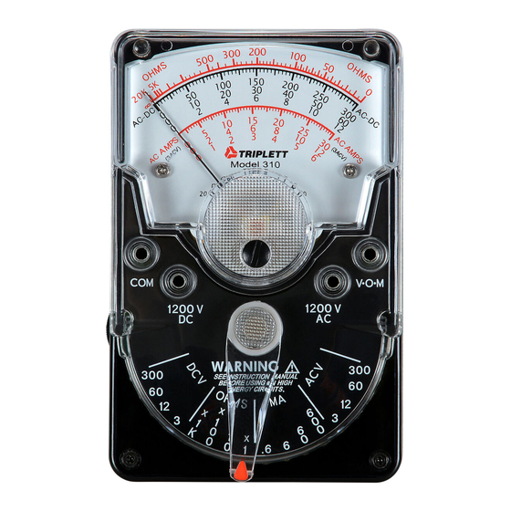
Page 16: Control Location Diagram
CONTROL LOCATION DIAGRAM DIAL SCALE INDICATOR NEEDLE POLARITY REVERSING SWITCH (310-C ONLY) ZERO ADJUSTMENT SCREW BLACK TEST LEAD TEST LEAD INPUT INPUT JACK JACK V-O-M RANGE SELECTOR SWITCH OHMS ADJUST CONTROL VARIOUS RANGE SETTINGS... -
Page 17: Dc Voltage Measurements
0-3 through 0-300 Volts: 1. Insert test leads in VOM and COM jacks. 2. Set Range Switch to appropriate DCV range. 3. Set Polarity Switch to desired polarity (310-C only) 4. Connect probes across circuit to be measured. 5. Energize circuit. - Page 18 DC VOLTAGE MEASUREMENTS POLARITY REVERSING SWITCH (310-C ONLY) OHMS ADJUST CONTROL V-O-M 1200V SAFETY FIRST!
-
Page 19: Ac Voltage Measurements
2. Set Range Switch to 3 ACV. 3. Connect probes across circuit to be measured. 4. Energize circuit. 5. Read voltage on the black AC-DC scale. DO NOT TOUCH THE VOM while it is connected to high voltage! *Model 310-C is 0-600 Volts. - Page 20 AC VOLTAGE MEASUREMENTS POLARITY REVERSING SWITCH (310-C ONLY) OHMS ADJUST CONTROL V-O-M 1200V 1200V Set Range 300 ACV SAFETY FIRST!
-
Page 21: Resistance Measurements
RESISTANCE MEASUREMENTS X1 through X1K Ohms: 1. Insert test leads into VOM and COM jacks. 2. Set Range Switch to appropriate OHMS range. 3. Short test probes together. 4. Adjust OHMS ADJUST CONTROL until meter reads zero ohms. 5. Connect probes to component to be measured. 6. - Page 22 RESISTANCE MEASUREMENTS POLARITY REVERSING SWITCH (310-C ONLY) OHMS ADJUST CONTROL V-O-M 1200V 1200V SAFETY FIRST!
-
Page 23: Dc Current Measurements
0-.6 through 0-600 Milliamperes: 1. Insert test leads into VOM and COM jacks. 2. Set Range Switch to appropriate mA range. 3. Set Polarity Switch to desired polarity (310-C only) 4. Connect the probes in series with the circuit (use alligator clips). - Page 24 DC CURRENT MEASUREMENTS POLARITY REVERSING SWITCH (310-C ONLY) OHMS ADJUST CONTROL V-O-M 1200V 1200V – LOAD SAFETY FIRST!
-
Page 25: Measuring Output Volts (Db)
MEASURING OUTPUT VOLTS (dB) POLARITY REVERSING SWITCH (310-C ONLY) OHMS ADJUST CONTROL V-O-M 1200V 1200V AUDIO 600Ω AMPLIFIER SAFETY FIRST! To read Output Voltage use the same procedure as shown on page 17 for AC Voltage and convert readings to dB using the... - Page 26 MEASURING OUTPUT VOLTS (dB)
-
Page 28: Accessories
ACCESSORIES Carrying Cases: Model 369: Model 369-S: Cat. No. 10-1258 Cat. No. 10-1791 Model 369-T Model 369-V: Cat. No. 10-1608 Cat. No. 10-2959... -
Page 29: Maintenance
79-695: Test leads with Pin Cushion Clips 79-722: Test leads with Spike Clips MAINTENANCE FOR MODEL 310/310-C Battery Replacement If the pointer cannot be adjusted to full scale on the X1, X10, or X100 OHMS ranges, replace the 1.5V bat- tery. - Page 30 In the unlikely event that you must return your Triplett equipment for repair, the following steps must be taken. 1) Call 1-800-TRIPLETT to obtain a Return Material Authorization (RMA) number from Customer Service. 2) Enclose a copy of the original sales receipt showing date of purchase.
-
Page 31: Triplett Limited Warranty
The purchaser agrees to assume all liability for any damages and bodily injury which may result from the use or misuse of the product by the purchaser, his employees, or others, and the remedies provided for in this warranty are expressly in lieu of any other liability Triplett Instruments may have, including incidental or consequential damages. - Page 34 TRIPLETT Test Equipment & Tools 850 Perimeter Road, Manchester, NH 03103 PHONE: 800-TRIPLETT FAX: 603-622-2960 www.triplett.com...
Need help?
Do you have a question about the 310 and is the answer not in the manual?
Questions and answers