Advertisement
Quick Links
CONTENTS
1. Introduction
2. Safety Rules and Warnings
3. International Symbols
4. Product Features
5. Specifications
6. Front and Rear Panels, Display Details 12 - 17
7. Preparation for Use
8. General Measurement Procedures
9. Specific Measurement Procedures
10. Maintenance
11. Accessories
12. Warranty
1: INTRODUCTION
The Triplett Model 9310-A is a 3 3/4 digit, handheld, battery operated, autoranging
Clamp-On Ammeter and Multi-tester. It performs the basic electrical measure-
ments required by the homeowner as well as advanced measurements useful to
the professional electrician. It measures AC and DC Voltage, AC and DC Current,
and Resistance (Ohms). It also has a Diode Test function, and a Continuity Beeper.
Advanced functions include the measurement of Capacitance, Frequency, and Tem-
perature. A backlit LCD display makes the meter useful in areas with poor lighting
and convenience features like Data Hold and Auto Power Off add to the useful-
ness of the product. Overload protection makes the meter resistant to damage
from accidental overloads.
Visit us at www.TestEquipmentDepot.com
Triplett Model 9310-A
AC & DC Voltage
AC & DC Current
Resistance
Diode
Continuity
Capacitance
Frequency & Duty Cycle
Temperature
99 Washington Street
Melrose, MA 02176
Phone 781-665-1400
Toll Free 1-800-517-8431
PAGE
1
2 - 7
8
8
9 - 11
18 - 19
20 - 21
22 - 31
22 - 24
24 - 25
26 - 27
28
28 - 29
29 - 30
30 - 31
31
32
33
34
1
84-857
12/04
Triplett Model 9310-A
Advertisement

Related Manuals for Triplett 9310-A


Summary of Contents for Triplett 9310-A
- Page 1 11. Accessories 12. Warranty 1: INTRODUCTION The Triplett Model 9310-A is a 3 3/4 digit, handheld, battery operated, autoranging Clamp-On Ammeter and Multi-tester. It performs the basic electrical measure- ments required by the homeowner as well as advanced measurements useful to the professional electrician.
- Page 2 2.9 Check the condition of the test leads before making a measurement. Do not use the test leads if there is damaged insulation or exposed metal. Failure to observe this precaution may result in damage to the meter or injury to the user. Triplett Model 9310-A...
- Page 3 2.18 Do not apply voltage or current to the input of the meter when it is set to the Temperature measurement mode. Doing so may damage the meter and/or injure the user. 2.19 Do not attempt to measure current on bare conductors that are elevated above earth ground by more than 600V AC. Triplett Model 9310-A...
- Page 4 Condensation of water, inside and outside of the meter, may produce dangerous measuring conditions. Allow the meter to warm to room temperature before using. Failure to observe this precaution may result in damage to the meter or injury to the user. Triplett Model 9310-A...
- Page 5 This helps prevent you from accidentally touching a hot wire, since you need to concentrate on only one test lead. Failure to observe this precaution may result in damage to the meter or injury to the user. Triplett Model 9310-A...
- Page 6 Failure to observe this precaution may result in damage to the meter or injury to the user. Test Equipment Depot - 800.517.8431 99 Washington Street Melrose, MA 02176 Triplett Model 9310-A TestEquipmentDepot.com...
- Page 7 2.50 Do not use the thermocouple to measure the temperature of objects that are electrically “live”. Failure to observe this precaution may result in damage to the meter or injury to the user. Triplett Model 9310-A...
- Page 8 4.12 Continuity Beeper 4.13 Diode Test 4.14 Data Hold 4.15 Relative Mode cancels zero error and offsets 4.16 Backlit LCD Display 4.17 Overload Protection 4.18 Double Insulated Design 4.19 CE Mark (EMC / LVD) 4.20 3 Year Warranty Triplett Model 9310-A...
- Page 9 8.63 x 3.31 x 1.75 inches (L x W x H) 5.10 Weight: 338 grams, 0.75 lbs. (w/ battery, w/o leads) 5.11 Battery: 1 standard 9 volt alkaline battery (Triplett PN 37-48) 5.12 Battery Life: approx. 300 hours continuous usage except for current ranges.
- Page 10 A Ω Ω i t c : ) I 4 Ω 0 Ω 4 Ω 1Ω 0 4 Ω 0 1 Ω ± 1 Ω Ω 4 Ω 1 Ω 0 4 Ω 0 1 Ω ± Triplett Model 9310-A...
- Page 11 ± 4µF ± 0 4 µF 1 µF ± ± t i s i v i : y t ± ± ± t i s i v i : y t r a l Triplett Model 9310-A...
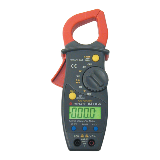
- Page 12 FIGURE 1 FRONT PANEL OF 9310-A Test Equipment Depot - 800.517.8431 Triplett Model 9310-A 99 Washington Street Melrose, MA 02176 TestEquipmentDepot.com...
- Page 13 6: 9310-A FRONT & REAL PANEL, DISPLAY DETAILS 1) Centering Marks – Position the conductor within the jaws at the intersection of the indicated marks in order to meet the specified accuracy. An additional error of several percent may result if conductor is not properly positioned.
- Page 14 Hz jack is negative with respect to the COM jack. It can also be displayed in the A mode, when the measured current is reversed to the direction of the polarity arrow. Note: Polarity arrow indicates current flow from positive to negative. Triplett Model 9310-A...
- Page 15 Voltage Annunciators – These annunciators are displayed whenever Voltage is being measured. The displayed annunciator indicates the range of voltage that is being measured. Current (Amperes) Annunciator – This annunciator is displayed when ever the Current (Amps) measurement mode is active. Triplett Model 9310-A...
- Page 16 Overload Indication – Figure 3 shows the Overload Indication. This is the display when the input exceeds the display capability of the Meter. If measuring voltage or current, remove the input immediately. Depending on the meter setting, the decimal points may or may not be present. Triplett Model 9310-A...
- Page 17 15) Battery Cover – After the Battery Cover Screw has been removed, the Battery Cover may be lifted to gain access to the battery. Install battery paying attention to battery wires. The wires must be correctly positioned for the cover to fit tightly on the meter. Triplett Model 9310-A...
- Page 18 Battery Cover by removing the Battery Cover Screw. The Battery Cover is a tight fit and a small straight blade or Philips screw driver can be helpful in removing it. Test Equipment Depot - 800.517.8431 Triplett Model 9310-A 99 Washington Street Melrose, MA 02176 TestEquipmentDepot.com...
- Page 19 For example, if D-HOLD is applied when the meter is reading zero, and 120VAC is subsequently applied, the meter will continue to read zero. Failure to observe this precaution may result in damage to the meter or injury to the user. Triplett Model 9310-A...
- Page 20 Preparation for Use section of this manual (Section 7.0). WARNING!!! THE MODEL 9310-A IS INTENDED FOR USE ONLY BY PERSONNEL TRAINED IN THE PROPER SAFETY PROCEDURES AND WHO CAN RECOGNIZE SHOCK AND SAFETY HAZARDS.
- Page 21 Meter may require the hand holding the meter to come close to other circuitry which could prove a serious shock hazard. WARNING!!! WHENEVER TOUCHING THE METER IN AN ENERGIZED CIRCUIT, THE USE OF A LINEMAN’S GLOVE CONFORMING TO ASTM D120 REQUIRED. Triplett Model 9310-A...
- Page 22 Attach the test leads to the Tester. The red lead is connected to the Ω Hz Jack, and the black lead is connected to the COM Jack. Connect the test leads across the circuit to be measured. See Figure 5. Triplett Model 9310-A...
- Page 23 (you’ll need to press the button repeatedly to get to the next lower range). Reconnect the test probes to the circuit and observe the reading on the LCD dis- play. If the RANGE is already on the lowest selection (i.e. 400mV), no greater measurement resolution can be obtained. Triplett Model 9310-A...
- Page 24 OL for longer than 2 seconds, remove the Jaws from the circuit immediately. An overrange condition exists. Do not attempt to measure this current. It exceeds the capability of the meter. Test Equipment Depot - 800.517.8431 Triplett Model 9310-A 99 Washington Street Melrose, MA 02176 TestEquipmentDepot.com...
- Page 25 WARNING!!! WHENEVER TOUCHING THE METER IN AN ENERGIZED CIRCUIT, THE USE OF A LINEMAN’S GLOVE CONFORMING TO ASTM D120, IS REQUIRED. Remove the Meter from the circuit by opening the Jaws and carefully withdrawing Triplett Model 9310-A...
- Page 26 Overrange OL indication. Short the leads together. The display should indicate less than 000.5 Ohms. Connect the leads to the circuit or component under test. See Figure 7. FIGURE 7 RESISTANCE, DIODE, AND CAPACITANCE TESTS Triplett Model 9310-A...
- Page 27 For example, if a 113 Ohm resistor is connected, the meter will display “013.0”….. the difference between the 100 Ohm resistor and the 113 Ohm resis- tor. Similarly, if a 92 Ohm resistor is connected, the meter will display “-008.0”. Triplett Model 9310-A...
- Page 28 Do not apply voltage or current to the meter when it is set to Refer to Section 7.0, Preparation For Use, and Section 8.0, General Measurement Procedures, before attempting any measurements. Select Continuity Test by rotating the FUNCTION switch to the position and Triplett Model 9310-A...
- Page 29 This is the residual capacitance error. To “zero out” this error, press the REL and DCA ZERO ADJ button. The displayed reading should change to 00.00nF, and the REL annunciator should appear in the display. Triplett Model 9310-A...
- Page 30 In the Duty Cycle mode, the meter usually displays “000.0%”. Using the appropriate precautions, connect the test leads to the circuit to be mea- sured. Read the Frequency or Duty Cycle from the display. Test Equipment Depot - 800.517.8431 Triplett Model 9310-A 99 Washington Street Melrose, MA 02176 TestEquipmentDepot.com...
- Page 31 Special high temperature bead style probes are available from a number of sources. The probe is a standard “K” type thermocouple. To make non-contact measurements of surfaces, including electrically “live” sur- faces, the user may wish to consider obtaining an Infrared Pyrometer, such as the Triplett PT10. Triplett Model 9310-A...
- Page 32 10: MAINTENANCE Your Triplett Model 9310-A Digital Clamp Meter is a precision measuring instru- ment and, when used as described in this manual, should not require mainte- nance. There are no internal user serviceable parts (fuses, etc). However, periodic calibration of the meter will insure that it is accurate and per- forming in accordance with its design specifications.
- Page 33 11: ACCESSORIES 11.1 The Triplett Model 9310-A package contains the following items: Model 9310-A Clamp-On Meter Test leads w/ Screw-On Alligator Clips (Triplett PN: 79-760) 9 Volt Battery (Triplett PN: 37-48) Instruction Manual (Triplett PN: 84-856) Carrying Case (Triplett PN: 10-4289)
- Page 34 No representative of Triplett Corporation or any other person is authorized to extend the liability of Triplett Corporation in connection with the sale of its products beyond the terms hereof.
- Page 35 NOTES Triplett Model 9310-A...
- Page 36 NOTES Test Equipment Depot - 800.517.8431 Triplett Model 9310-A 99 Washington Street Melrose, MA 02176 TestEquipmentDepot.com...
Need help?
Do you have a question about the 9310-A and is the answer not in the manual?
Questions and answers