
Related Manuals for CTC Union TSB4000 Series


Summary of Contents for CTC Union TSB4000 Series
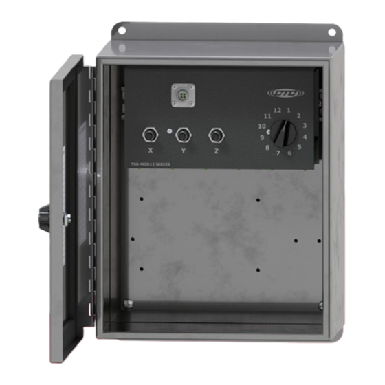
- Page 1 TSB4000 Series Modular Switch Box TSB4000 Series Modular Switch Box 36 Channel 36 Channel Product Manual Product Manual...
-
Page 2: Table Of Contents
Table of Contents • Introduction . . . . . . . . . . . . . . . . . . . . . . . . . . . . . . . . . . . . . . . . . . . . . . . . . . . . . . . . . . . . . . . . . . .3 •... -
Page 3: Introduction
. The TSB4000 Series 12 Switched Triaxial Channel stainless steel modular switch box is used to convert the four-conductor input wiring of up to 12 remotely installed triaxial accelerometers to switched BNCs and a switched four-pin connector for 36 channels of measurement . -
Page 4: Product Dimensions & Diagram
Product Dimensions Front View Side View Figure 1. Dimensions Four-pin MIL BNC Output Output Connector Connectors Measurement Switch Location Card Figure 2. Diagram... -
Page 5: Mounting Instructions
Mounting Instructions Note: if you have purchased a modular switch box without cable entries provided, you should add your own entry prior to mounting the modular switch box . CTC does not recommend drilling holes in the top of the enclosure due to access and moisture concerns . -
Page 6: Conduit Entry
Conduit Entry If you are running conduit to your enclosure, ensure the conduit cable entry enters from the bottom of the enclosure when mounted . Note: To ensure moisture will not flow into the enclosure, a hole should be drilled at the lowest point in the conduit to provide drainage for any moisture . -
Page 7: Grounding
Grounding Ensure the shield ground wire on the TSB4000 Series modular switch box is grounded to earth ground . A. Mounting to Earth Ground When mounting TSB4000 Series modular switch boxes to earth ground (such as an I-Beam), no additional steps are necessary, as the enclosure is grounded internally . -
Page 8: Installation Of Sensor/Signal Input Cable
B. Mounting to non-grounded structure When mounting the modular switch box to a non-grounded structure, ensure the shield ground wire or customer supplied ground wire is tied to a source of earth ground . Figure 6. Ground Wire Placement Sensor Installation Installation of sensors/signal input cable Feed blunt end through the cable entry at the bottom of the enclosure . - Page 9 Figure 8. Bottom View Figure 7. Front View Strip outer jacket of cable back 1¼ in . and remove all of the shielding . Separate the internal wires from the shield . Strip red and black insulation back ¼ in . (-) Common Shield / Drain wire (+) Channel Y...
- Page 10 Inputs Inputs Inputs Inputs Inputs Inputs Sensor Inputs Green = Signal/Power X Axis Red = Signal/Power Y Axis White = Signal/Power Z Axis Black = Common Grey = Shield (Ground) Sensor Inputs Sensor Inputs Green = Signal/Power X Axis Green = Signal/Power X Axis Red = Signal/Power Y Axis Red = Signal/Power Y Axis White = Signal/Power Z Axis...
-
Page 11: Post Installation Testing
Post Installation Testing The TM1018 Accelerometer Verification Meter can be used to verify cable conductivity, sensor location and proper wiring connections . The Verification Meter will indicate if the sensor, cable and/or junction box is in working condition . It will also confirm bias voltage of the accelerometer, which will inform you of the operation of the internal accelerometer amplifier . - Page 12 The following LED Readout indicates the circuit integrity: Green LED: Normal . Indicates proper connection and an output bias will be given, indicating the health of the sensor (4 – 16 V indicates a healthy accelerometer) . Yellow LED: Open Circuit . Indicates one of the following: a .
- Page 13 Warranty & Refund Warranty All CTC products are backed by our unconditional lifetime warranty . If any CTC product should ever fail, we will repair or replace it at no charge . Refund All stock products qualify for a full refund if returned in new condition within 90 days of shipment .
Need help?
Do you have a question about the TSB4000 Series and is the answer not in the manual?
Questions and answers