Advertisement
Quick Links
Advertisement

Related Manuals for EKKO EK18A


Summary of Contents for EKKO EK18A
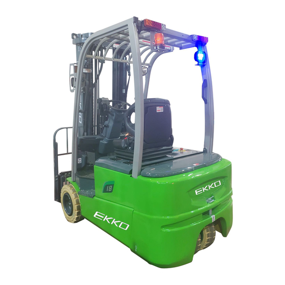
- Page 1 Service Manual EK18A Three Wheel Electric Forklift Warning You must understand the operation instructions in this manual before using it. Note: · Please check the last page of this document and name plate for all current product type identification. Keep it for future use...
-
Page 2: Table Of Contents
Manual Maintenance List ......................................1 Overview of main components ................................ 2 Lubrication point ....................................3 Check and refill hydraulic oil ................................4 Check the fuse ......................................5 Fault Analysis ......................................... 6 Common Fault analysis ..................................7 The fault code is displayed ................................. 8 Wiring/circuit Diagram ..................................... -
Page 3: Maintenance List
1 Regular maintenance Only qualified and trained personnel should perform maintenance work on this vehicle. Before maintenance, remove the cargo from the fork and lower the fork to the lowest position. If you need to lift the vehicle, use the specified lashing or jacking equipment.Before operation, place safety devices (such as designated jacks, wedges or wood blocks) under the vehicle to prevent accidental drop, movement or sliding. - Page 4 Check the electrical connections Check the function of the emergency switch • Check whether the power drive system is noisy or damaged • Test electricity meter • Check whether the correct fuse is used • Detect warning signals • Check the current contactor •...
-
Page 5: Lubrication Point
Lubrication point Lubricate marked points according to maintenance list.Required grease specification: DIN 51825 standard grease Pic1:transmission chain Pic2:The rail of gantry... -
Page 6: Check And Refill Hydraulic Oil
Pic3: Drive axle clamp Check and refill hydraulic oil Recommended hydraulic oil model according to temperature:: Ambient –5℃~25℃ >25℃ temperature HVLP 32, HLP 46, mark DIN 51524 DIN 51524 Viscosity 28.8-35.2 41.4 - 47 1.5 L Waste materials such as waste oil, waste batteries or other materials must be treated and recycled in accordance with national regulations, and returned to the recycling company for recycling if necessary. -
Page 7: Fault Analysis
A. Check the electrical fuse 10Aelectrical fuse 300A fuse List 2: Fuse specification specification Fuse 1 Fuse 01 300A 2 Fault analysis If the vehicle continues to malfunction, follow the instructions of the manual. 2.1 Common fault analysis 2.1.1 Hand and foot brake common faults and troubleshooting methods •... - Page 8 4. The brake shoe clearance is not Adjust adjusted well 5, the total pump pump bowl Check the cause of damage and deformation, damage or excessive replace wear 6. There are oil stains on the surface of Clean up brake drum hole 1.
- Page 9 • 2.1.2 Steering system common faults and troubleshooting methods Failure cause maintenance 1. There is air in the hydraulic pipeline exhaust components of the steering system 2, the working oil oil level is too low, Gas exhaust inhale air 3. The shunt valve hole is blocked and Cleaning and replacement the spool is stuck steering...
- Page 10 2.1.3 Lifting system common faults and troubleshooting methods Failure cause maintenance 1. The gap between the upper side Reduce adjusting gasket roller of the outer door frame and the channel steel of the inner door frame is too large > 1mm 2.
- Page 11 1. Insufficient amount of working oil Come on 2, speed limit valve throttle hole is Unpick and wash blocked by stolen goods 3, the safety valve slide blocked, stuck Cleaning and repairing 4. Leakage of suction pipe weld at the Repair welding, bottom leakage The over lift filter screen in the tank...
- Page 12 2, the horn switch contact is poor The speaker is broken Long horn ring 1, horn switch contact long 1. The buzzer is broken The reversing buzzer doesn't 2. Poor contact of reversing switch work 3. Poor line connection and plug 2.1.5Gearbox fault causes and troubleshooting methods Fault cause and elimination method Failure...
- Page 13 9. The bolts between pieces are not Tighten the stud bolts with specified evenly stressed or tightened torque 1, the control mechanism is not Check the control lever flexible 2, the valve stem is squeezed by dirt Clean valves, fuel tanks and pipelines 3, return spring deformation or Remove the back cover for inspection Stem cannot be...
- Page 14 4. Steering gear failure Replace the steering gear 1. There is foreign matter stuck Clean valves, fuel tanks, pipelines, etc between the overflow valve or overload valve main spool and valve seat 2. The damping hole is blocked Hydraulic oil pollution is serious, No action of clean the hydraulic system cylinder...
- Page 15 absorption is 2. The tank level is too low The tank is filled with hydraulic fluid not smooth as required 3. The installation position of the oil According to the suction range of the pump is too high; Suction range oil pump, it is within 500mm exceeds specified 4, the oil temperature is too low, the...
- Page 16 1. Most cases are caused by Keep oil level high and seal must be insufficient oil absorption of oil pump, reliable to prevent oil contamination such as blockage of oil absorption filter; Oil level is too low; Inhalation of air; Suction air at oil seal, etc 2.
- Page 17 1、Walk and lift controller fault code Controller Over 1, motor external U,V or W connection short circuit Code Fault name Possible cause current 2. Motor parameters do not match 3. The controller is faulty Current Sensor Fault 1, motor U, V, W through the stator on the car body short circuit, resulting in leakage 2.
- Page 18 Motor Temp Hot 1. The motor temperature reaches or exceeds the alarm temperature Cutback set by the program, resulting in the reduction of current output 2. The motor temperature parameters are incorrectly set 3. If the motor does not use a temperature sensor, program parameters "Temp Compensation"...
- Page 19 1, accelerator potentiometer output voltage is too low Throttle Wiper Low 1, potentiometer 2 output voltage is too high Pot2 Wiper High 1, potentiometer 2 output voltage is too high Pot2 Wiper Low 1, potentiometer impedance is too low Pot Low Over current EEPROM Failure 1.
- Page 20 program 1. The vehicle is still moving after the electromagnetic brake EM Brake Failed to Set command is set. 2, electromagnetic brake braking force is too small 1. Due to motor blocking or encoder Encoder LOS (Limited The failure causes the restricted operating state to be Operating Strategy) The activation 2.
- Page 21 Press this button to read the fault content 2.3 If the instrument does not display the fault, according to the principle diagram to find the input signal is normal, such as vehicle without walking, need to make sure the input of the accelerator and the direction switch is normal, the accelerator signal lines 1 a16, direction of signal is a22 1 and 1 a33, multi meter measuring controller plug place are available, and between the signal and the cathode, the corresponding switch operation,Whether there is voltage change is shown as follows:...
- Page 22 Speed mode H 3Circuit/circuit diagram 3.1Electrical schematic diagram...
- Page 23 3.2 液 原理...
- Page 24 Hydraulic oil inspection Clear not discoloration good good can be used Appearance odor condition results check viscosity, if qualified can color transparency good with other oil mix continue to use to separate moisture or replace Color changes like milk well mixed with air and water hydraulic fluid The color becomes dark brown...
- Page 25 1. Drive axle 2. Tire 3. Motor 4.Flat washer 5. Spring washer 6.Screw 7. Gearbox 8. Flat pad 9.Spring washer 10. Screws 4.1 Drive axle structure drawing Drive axle is mainly composed of bridge shell, wheel, axle, brake and tire, bridge shell is integrally cast structure, tire through the rim fit with stud bolt and nut on the wheel hub, power through a differential drive axle shaft, finally by the wheel turns the front wheel, wheel hub by taper roller bearing is loaded on the axle housing, so only bear the torque of driving...
- Page 26 4.2 Transmission diagram The gearbox is partially located between the drive axle and the travelling motor, and the mechanism's two pairs of cylindrical helical gears reduce the speed from the travelling motor's output shaft and increase the torque from the transmission shaft, which is then transmitted to the differential.
- Page 27 4.3 Differential structure drawing 1. Deep groove ball bearing 2. Nut 3.Left differential case 5. Washer 6. Gear 7. Shaft 8.Half shaft gear 9. Half shaft washer 10. Right differential housing 11.Gear ring 12. Bolts...
- Page 28 5 steering system The steering system consists of steering wheel, steering shaft, steering gear, steering oil pump and steering bridge. Steering shaft through the universal joint connected to the steering gear and the connecting shaft through the universal joint connected with the steering wheel, steering column can be tilted to the appropriate location, steering axle in the tail at the back of the chassis frame, left and right sides respectively have a steering knuckle, driven by steering cylinder piston rod through the connecting rod steering knuckle steering, the steering wheel deflection, implementation.
- Page 29 friction between the disc and the brake drum increases, because the main brake shoe to the secondary brake shoe a much greater pressure than the brake pump pressure, so as to produce a lot of braking force. Parking brake is mainly used in the parking state to prevent accidents caused by sliding slope. The parking brake is equipped with a travel switch and the control circuit is disconnected during parking.
- Page 30 compressed by the return spring of the brake shoe, so that the brake fluid returns to the master pump (piston front chamber) through the one-way valve, the piston returns to the original position, and the brake fluid in the master pump flows back to the oil storage tank through the oil return port.
- Page 31 hand braking Hand brakeing cable Hydraulic system The hydraulic system is composed of main oil pump, multi-way valve, lifting cylinder, inclined cylinder and oil channel. The oil pump motor drives the gear pump to provide hydraulic power, two lifting cylinders are responsible for the lifting of the fork, two inclined cylinders complete the front and back tilt action of the door frame, and one side cylinder completes the left and right side movement of the tray frame.
- Page 32 7.1 Multitandem valve Multi - way valve by valve body, slide valve, relief valve.The valve body is assembled together by bolts and nuts. The pressure of the main safety valve has been adjusted before leaving the factory. Users are not allowed to adjust it casually. 1, safety valve 2, micro switch bracket 3, oil return port 4, lifting speed sensor...
- Page 33 7.2 Schematic drawing of lifting cylinder and tilting cylinder 1. Dust ring 2. Cylinder head 3.O ring 4.Cylinder block 6 piston 7 steel wire retainer 8 support ring 9.Sealing ring 10. Baffle 11. Buffer sleeve 12. Cylinder pin 13.bearing...
- Page 34 1. Oil cup 2. Cylinder block 3.Piston 5. Sealing ring for hole 6. Supporting ring for hole 7.Piston rod 9. Guide sleeve 10. Bearing 11. O-ring 12.Seal ring for shaft 13. Dust ring 14. Nut 15.Joint bearings 17. Elastic retainers for holes 18. Right Angle joints...
- Page 35 8 Jacking system The lifting system consists of internal and external door frame, cargo fork frame, retaining shelf, lifting cylinder, inclined cylinder, lifting chain and so on. It is the holding mechanism of forklift truck for loading and unloading operations. Forklifts are standard with a two-stage wide view frame.
- Page 36 9 Electric System Electrical system mainly includes battery, traction motor, pump motor, traction motor controller and pump motor controller, steering combination switch, multi-way valve block controller, display instrument, combined control switch, instrument and lighting device, etc 9.1 display The display has six built-in red liquid crystal displays, which provide the operator with some easy information about the operation of the vehicle's mechanism.
-
Page 37: 5、Curtis Handheld Unit
5、CURTIS Hand held unit Precautions for operation: The attention function of the hand-held unit is to facilitate vehicle inspection and maintenance. It is not allowed to adjust the controller parameters without the approval of the vehicle manufacturer, so as to avoid vehicle and personal safety accidents. - Page 38 fault diagnosis Warning: The control system can affect the vehicle's acceleration rate, deceleration rate, hydraulic system and braking.A dangerous situation can occur if the vehicle control system is not programmed correctly or exceeds safety.Only the vehicle manufacturer or an authorized service agent can program the control system The programmer has two interfaces, one is used to communicate with the electric control, the other is used to communicate with the PC, the programmer has a battery box and a memory card slot...
- Page 39 The function keys Since the function of the three keys is determined by the specified content, the three keys are blank.At any given time, the function of the button is displayed on the LCD screen above. Direction arrow key The displayed information can be selected up, down, or left by four directional buttons.
- Page 40 -The menu structure The main menu consists of nine sub-menus, and each sub-menu is displayed with a specific icon. Each item in the sub-menu is arranged by hierarchy. Some menus contain only one item of information, but most menus contain more than one item of information, and open each item folder to access the next level of sub menus.Expand the table through the grid option, enter a group of execution commands through the dialog box option, and return to the upper menu regardless of the interface by pressing the left direction button.
- Page 41 Clear All is used to Clear historical fault folders.A function key is highlighted only when there are historical failures in the historical failures folder and grayed out when there are no historical failures. Programming menu On the main menu, Select The Programming icon and press Select to access the menu. Save and restore parameter Settings files (.cpf files) through programming menus Save.cpf File (Save.cpf File) Use the save.
Need help?
Do you have a question about the EK18A and is the answer not in the manual?
Questions and answers