Table of Contents
Advertisement
Quick Links
Advertisement
Table of Contents

Related Manuals for Autel EVO Max Series


Summary of Contents for Autel EVO Max Series
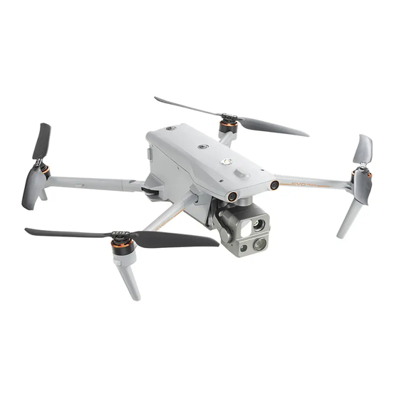
- Page 1 Multirotor Aircraft User Manual V1.2.2 2024.09...
-
Page 2: Eu Declaration Of Conformity
Trademark Information , Autel Enterprise trademarks are registered trademarks of ™ the Autel Robotics Co., Ltd. (hereinafter referred to as "Autel Robotics") in China or other countries/regions. Copyright This manual and other documentations mentioned in this manual is copyrighted by Autel Robotics Co., Ltd. - Page 3 To facilitate reading, the following table displays terms and acronyms that may be used in the manual: Autel Robotics: Autel Robotics Co., Ltd. Aircraft: EVO Max Series Multirotor Aircraft, including EVO Max 4T, EVO Max 4T XE and EVO Max 4N. Battery: ABX40 Smart Battery or ABX41 Smart Battery ...
-
Page 4: Manual Guide
Getting Tutorial videos, User Documents, and Relevant Software You can scan the QR codes below or visit the following links to access tutorial videos and user documents or download relevant software for the EVO Max series multirotor aircraft: To watch tutorial videos, please visit: https://www.autelrobotics.com/videos/evo-max-series/. - Page 5 Store the aircraft and its accessories out of the reach of children and pets. If you do not abide by the Safety Operation Guidelines, Autel Robotics shall not be responsible for any product damage or personal and property loss during use, and shall not provide any free warranty service.
-
Page 6: Warranty Policy
Autel Robotics guarantees users who purchase products through its official authorized channels that: Under normal use, the Autel Robotics products you purchase will be free from material and workmanship defects during the warranty period. If you can provide a valid purchase receipt, the warranty period of this product is calculated from the midnight of the next day after you receive the product. -
Page 7: Update Log
Call Autel Robotics customer support at (844) MY AUTEL or (844) 692-88 35. Contact dealers authorized by Autel Robotics. Important All data stored on the product may be erased during the repair process. To avoid data loss, please back up important files in your aircraft or remote controller before the product is under warranty. - Page 8 added ABX41 smart battery. Adjusted some function descriptions. Added Fusion 4T XE parameters and relevant V1.2.1 2024.08 description. Added obstacle description about auto landing process. V1.2.2 2024.09 Added 1158 propeller and 1136 propeller description. Compliance with FCC/ISED Any Changes or modifications not expressly approved by the party responsible for compliance could void the user's authority to operate the equipment.
- Page 9 This equipment complies with FCC/ISED radiation exposure limits set forth for an uncontrolled environment. This equipment should be installed and operated with minimum distance 20cm between the radiator& your body. This transmitter must not be co-located or operating in conjunction with any other antenna or transmitter.
-
Page 10: Table Of Contents
Table of Contents Chapter 1 Product Overview ....................... 1 1.1 Introduction ..........................1 1.2 What's In The Rugged Case....................2 1.3 Product Acceptance Checklist ....................3 1.4 UAS Introduction ........................4 Chapter 2 Flight Safety ........................ 9 2.1 Legal Use Notice ........................9 2.1.1 Chinese Mainland ...................... - Page 11 2.12.1 Compass Calibration ....................29 2.12.2 IMU Calibration ......................31 2.12.3 Gimbal Calibration ....................33 2.13 Emergency Stop Propellers During Flight ................ 34 2.14 Remote Identification ......................35 2.15 Standard Flight Operation Process .................. 35 2.15.1 Pre-Flight Checklist ....................35 2.15.2 Basic Flight Process ....................
- Page 12 4.1.2 Communication Frequency Bands ................68 4.2 Installing the Remote Controller Lanyard ................. 70 4.3 Installing/Storing Sticks ......................71 4.4 Turning the Remote Controller On/Off ................72 4.5 Checking the Battery Level of the Remote Controller ............. 73 4.6 Charging the Remote Controller ..................74 4.7 Adjusting the Antenna Position of the Remote Controller..........
- Page 13 6.2 Main Interface........................104 6.3 Status Notification Bar ....................... 107 6.4 Toolbar..........................108 6.5 “Settings” Interface ......................112 6.6 Attitude Ball ......................... 121 6.7 "Map" Interface ........................122 6.8 Camera Interfaces ....................... 125 6.8.1 Camera Function Access ..................125 6.8.2 Camera Switch and Operation ................129 6.9 Flight Missions ........................
-
Page 14: Chapter 1 Product Overview
The EVO Max series multirotor aircraft adopts a foldable arm design and can hold its propellers for easy storage and transportation. The aircraft is equipped with a PSDK interface at its top, allowing you to add different industry-specific mounts on the aircraft to meet various operational needs. -
Page 15: What's In The Rugged Case
Chapter 1 Product Overview 1.2 What's In The Rugged Case The aircraft is packed and transported in a rugged case (with built-in shock absorption protective materials) and the items inside the case are as follows: Important Upon receiving the product, please inspect the rugged case in its integrity and confirm that its outer packaging is intact, with no signs of unpacking. -
Page 16: Product Acceptance Checklist
After unboxing the product, please check whether the actual items match the items described in the following packing list and carefully inspect the appearance of the aircraft and all accessories. If anything missing or damage is found, please contact Autel Robotics After-Sales Support or authorized dealers promptly. -
Page 17: Uas Introduction
Any damage or missing of these components may result in a malfunction. The RTK module is an optional accessory for enhancing aircraft positioning accuracy. Users can contact Autel Robotics to purchase the RTK module based on their needs. Table 1-3 Aircraft Component List... - Page 18 Max. Dimension: Includes propellers, 562×651×147 mm ABX40 smart battery, EVO Max 4T XE and a Fusion 4T XE EAN: 6924991135470 Autel Robotics Aircraft Gimbal. The firmware UPC: 889520215473 version of the aircraft is V1.8.2.237 or later. EAN: 6924991138020 UPC: 889520218023 Max.
- Page 19 For details about how to install a RTK module, see “3.12 Extension Interface” in Chapter 3. All the above components have passed Autel Robotics safety and compatibility tests. Users can purchase and use accordingly. In case of adding any third-party payload before flight, please reasonably evaluate the mounting weight and the gravity center of the aircraft after mounting.
- Page 20 24Q3 Android System V1.8.2.237 Based on Android 11 24Q3 Autel Enterprise V2.1.119 Flight Application 24Q3 The above information is for reference only. Both the remote controller and the aircraft have been upgraded to the latest versions before shipment. Users can use accordingly.
- Page 21 Chapter 1 Product Overview Users can, based on their own needs or preference, replace those system basic applications with third-party applications.
-
Page 22: Chapter 2 Flight Safety
Those who fail to implement real-name registration and paste registration marks will be punished by the regulatory authorities in accordance with relevant regulations. The aircraft is a light unmanned drone. Autel Robotics prohibits youth under the age of 18 from operating this aircraft. -
Page 23: The U.s
Chapter 2 Flight Safety Important According to the regulations outlined in the "Civil Unmanned Aerial Vehicle System Safety Requirements" in Chinese mainland, users are required to input their real-name registration number and Remote ID in the flight application after registration. Additionally, users should enable the Civil Aviation Administration's flight dynamic data reporting function and the aircraft will automatically enable Remote ID broadcast after power-on self-check. -
Page 24: The Eu
Chapter 2 Flight Safety 2.1.4 The EU Drone operators/owners must register with the National Aviation Authority (NAA) of the Member State in which they reside. (https://www.easa.europa.eu/drones/NAA). This product is not a toy and should not be used by children under the age of 16. ... -
Page 25: Flight Environment Requirements
Chapter 2 Flight Safety Do not fly in areas prohibited by local regulations without authorization. The prohibited areas may include airports, borders, major cities, densely populated areas, large event sites, emergencies (e.g., forest fires), and sensitive building facilities (e.g., nuclear power plants, power stations, transformer stations, prisons, traffic arteries, government buildings, and military facilities). -
Page 26: Wireless Communication Requirements
Chapter 2 Flight Safety 2.4 Wireless Communication Requirements Keep the aircraft at least 200 meters away from areas with strong electromagnetic interference, such as radar stations, microwave stations, and mobile communication base stations. Keep the aircraft at least 2000 meters away from drone interference equipment. Otherwise, the drone interference equipment and the aircraft cannot work at the same time. -
Page 27: Obstacle Avoidance System
Note When installing a function module to the aircraft, please choose a function module that has passed Autel Robotics safety and compatibility test as this kind of product has already passed flight safety test. When users are mounting payload, please ensure that the mounting point should be located at the center line of the aircraft and should not be beyond the area bracketed in the left picture in fig 2-1. - Page 28 Chapter 2 Flight Safety Fig 2-2 Front and rear visual obstacle avoidance lens modules of the aircraft Fig 2-3 Top and bottom visual obstacle avoidance lens modules of the aircraft Warning Do not block the lenses of the visual obstacle avoidance lens during flight, as it will affect the visual obstacle avoidance performance of the aircraft, potentially leading to flight accidents.
-
Page 29: Observation Range
Please be noted that the frequency band of the millimeter-wave radar is a hardware parameter, which cannot be adjusted through software. Autel Robotics ensures that the millimeter-wave radar frequency band of the EVO Max series drones complies with local legal regulations. -
Page 30: Visual Positioning Function
Chapter 2 Flight Safety the obstacle's ability to reflect electromagnetic waves and its surface size. The gray area represents the blind spot of a millimeter-wave radar, where the radar cannot detect obstacles. Observation Range of Radar and Visual Obstacle Avoidance Sensing Systems With the integration of radar and visual obstacle avoidance sensing systems, the aircraft achieves 720°... -
Page 31: Visual Obstacle Avoidance Function
Chapter 2 Flight Safety display the following warning prompts: If the takeoff point is inaccurate: The flight application will display a warning "GNSS signal is weak. The landing point may deviate." with a corresponding verbal warning. If GNSS signal is weak: The flight application will show a warning " GNSS signal is weak. -
Page 32: Auto-Return
Chapter 2 Flight Safety Flying over water surfaces or transparent object surfaces. Flying in environments with rapid and intense changes in lighting or direct exposure to strong light sources. Flying over extremely dim (with light intensity of less than 15 lux) or extremely bright object surfaces. -
Page 33: Manual Auto-Return Activation
Chapter 2 Flight Safety pull the pitch stick down to exit the auto-return. After exiting the auto-return, the RC will regain control of the aircraft. For more information, see “4.11.2 Take-off/Return-to-Home Button and Pause Button” in Chapter 4. Warning When the aircraft is in visual positioning mode or attitude mode, the auto-return function cannot be activated. -
Page 34: Behavior-Based Auto-Return Activation
Chapter 2 Flight Safety Warning When the low battery auto-return is triggered in the aircraft, it is recommended that the auto-return process should not be canceled. Otherwise, the aircraft may be unable to return to the home point due to insufficient power. ... -
Page 35: Auto-Return Obstacle Avoidance Process
Chapter 2 Flight Safety returns to the home point. If the current flight altitude is higher than 20 meters, the aircraft returns to the home point at the current altitude. If the current flight altitude is lower than 30 meters, the aircraft ascends to the altitude of 30 meters and 25 meters <... -
Page 36: Landing Protection Function
Chapter 2 Flight Safety 2.8 Landing Protection Function When the landing protection function is enabled, the aircraft will assess whether the ground conditions are suitable for landing before landing. For more information, see “6.5 “Settings” Interface” in Chapter 6. During the auto-return process, when the aircraft reaches above the home point and the landing protection function is enabled, the aircraft will execute the following strategies: 1. -
Page 37: Flight Restrictions And Unlocking Restricted Zones
2.10.1 Geofencing System Autel Robotics has developed a geofencing system for its aircrafts to ensure safe and legal flights. This system can provide real-time updates on airspace restriction information worldwide. In different restricted zones, the flight functions of the aircraft are subject to varying degrees of restrictions. -
Page 38: Restricted Zones
Permanent no-fly zones: The zones are pre-configured in the geofencing system at the factory and are regularly updated. Temporary no-fly zones: The zones are added by Autel No-Fly Zones Robotics in the geofencing system backend. (appear in red on the map) - Page 39 Chapter 2 Flight Safety unrestrictedly (relevant flights must comply with local regulations). Unlocked Zones If you unlock a no-fly zone with a valid permit, you can legally (appear in blue on the map) fly the aircraft within the validity period in the unlocked zone. In the flight application, if you tap on a restricted zone on the map, the following geofencing information will be displayed for this zone: ...
-
Page 40: Ugz Import
Chapter 2 Flight Safety When the aircraft approaches the warning zone boundary, the flight application will display a warning alert “The aircraft is close to the warning zone.” and after entering the warning zone, the App will display “Aircraft enters warning zone” to remind users to be cautious. -
Page 41: Altitude And Distance Limits
Aircraft S/N (Serial number): Multiple serial numbers can be applied at once. Autel account of UAS operator: Multiple accounts can be applied at once. Log in to the official website of Autel Robotics at www.autelrobotics.com/service/noflight/, enter the relevant information, and complete the waiver application. -
Page 42: Aircraft Calibration
Chapter 2 Flight Safety In the flight application, the altitude limit should be set between 20 meters and 800 meters, and the distance limit should be set between 20 meters and 5000 meters. During actual flights, the maximum altitude limit should be set no greater than the maximum altitude specified by local laws and regulations. - Page 43 Chapter 2 Flight Safety Table 2-4 Compass Calibration Step Operation Diagram After turning on the aircraft and the remote controller, tap " " > “ ” > “ ” > "Compass Calibration" > "Start Calibration" in the main interface of the flight application.
-
Page 44: Imu Calibration
Chapter 2 Flight Safety Hold the aircraft to keep it with the nose to the left and the side down. Rotate the aircraft 360° horizontally until interface prompts successful calibration. Please perform the calibration steps according to the tips shown in the compass calibration interface of the flight application. - Page 45 Chapter 2 Flight Safety Table 2-5 IMU Calibration Step Operation Diagram After turning on the aircraft and the remote controller, tap " " > “ ” > “ ” > "IMU Calibration" > "Start Calibration" in the main interface of the flight application.
-
Page 46: Gimbal Calibration
Chapter 2 Flight Safety Put the left side of the aircraft flat on ground until interface prompts next step. Put the right side of the aircraft flat on the ground until the interface prompts next step. Fold the arms, turn the aircraft nose up, and lay it on the leveled surface until interface... -
Page 47: Emergency Stop Propellers During Flight
Chapter 2 Flight Safety If the flight application prompts an alert ”Please calibrate the gimbal motor”, please follow the steps below to calibrate it. Table 2-6 Gimbal Calibration Step Operation Diagram Place the aircraft on a flat ground. After turning on the aircraft and the remote controller, keep the aircraft in a static state. -
Page 48: Remote Identification
If you stop the propellers when the aircraft has an initial velocity, the aircraft will fall along a parabolic trajectory. If the trajectory is unpredictable, do not stop the propellers. After completing an emergency landing, contact Autel Robotics promptly for a power system inspection and maintenance. -
Page 49: Basic Flight Process
Chapter 2 Flight Safety Make sure that the batteries of the aircraft and remote controller are fully charged, and the battery of the aircraft is installed in place, with the unlock button of the battery in a lock state. ... -
Page 50: List Of Safeguard
Chapter 2 Flight Safety 3. Please refer to "4.10.1 Stick Modes" and "4.10.2 Setting Stick Mode" in Chapter 4 to control the aircraft carefully. 4. Please refer to "4.10.3 Starting/Stopping the Aircraft Motor" in Chapter 4 to land the aircraft, and then turn off the motors. -
Page 51: Chapter 3 Aircraft
Make sure that the remote controller is connected to the Internet before starting the activation process. Otherwise, activation may fail. If activation fails, please contact Autel Robotics After-Sales Support for assistance. For how to match the aircraft with the remote controller in frequency, see “4.9 Frequency... - Page 52 Chapter 3 Aircraft the fuselage. Forward Visual Obstacle Used to sense the obstacles ahead and avoid the aircraft from Avoidance Sensing colliding with them. Lens Group Integrates multiple sensors stable shooting Gimbal Camera measurements during flight. Fig 3-2 Aircraft Rear View Table 3-2 Aircraft Rear View Details Name Description...
- Page 53 Chapter 3 Aircraft Warning The USB-C interface of the aircraft cannot be used for charging. Do not connect the included remote controller charger. For how to charge the aircraft, see “5.3.5 Charging the Smart Battery” in Chapter 5. Fig 3-3 Aircraft Top-Down View Table 3-3 Aircraft Top-Down View Details Name Description...
- Page 54 Chapter 3 Aircraft Fig 3-4 Aircraft Bottom-Up View Table 3-4 Aircraft Bottom-Up View Details Name Description Downward Visual Obstacle Used to sense obstacles below, and to the left and right of the Avoidance Lens aircraft and avoid collisions. Group An LED auxiliary light. In weak light conditions, it is used to enhance the ambient brightness of the landing area during the Auxiliary Light landing...
-
Page 55: Propeller
1158CCW respectively). Please refer to the “Packing List” and packaging for details. Important EVO Max series multirotor aircraft is currently compatible with two types of propellers: 1136 and 1158. 1136 propellers have been already out of service. Users (excluded EU users) who have bought this type of propellers can use 1158 propellers for replacement if they need to replace propellers. -
Page 56: Installing The Propellers
Chapter 3 Aircraft 2. First hold the rotor of the motor on the arm below the propeller to prevent it from rotating, press down on the propeller center shaft firmly, and then turn it in the unlocking direction marked on the propeller center shaft to detach the propeller. ... -
Page 57: Storing Propellers
Before each flight, make sure that all propellers are mounted correctly and securely. Please use the propellers provided by Autel Robotics. Do not mix propellers of different models. - Page 58 Chapter 3 Aircraft Fig 3-7 Arm Light Table 3-6 Arm Light Details Mode Front Arm Light ① Rear Arm Light ② During flight, the rear arm During flight, the front arm lights will blink alternately in a lights will blink green slowly GNSS Mode cycle of a period (green light following a pattern of a period...
-
Page 59: Strobe
Chapter 3 Aircraft Slow Blinking: blinks once every 2s (0.5s on/1.5s off). Fast Blinking: blinks twice per second. Ultra-fast blinking: blinks 5 times per second. 3.5 Strobe The aircraft is equipped with a strobe at the top of the fuselage to help identify the aircraft when flying at night. -
Page 60: Gimbal Camera
Chapter 3 Aircraft Fig 3-9 Auxiliary Light For how to turn the auxiliary bottom lights on or off, see “6.4 Toolbar” and “6.5 “Settings” Interface” in Chapter 6. Warning When the auxiliary bottom lights are set to auto mode, they will turn on automatically at an altitude of around 5 meters above the ground when the aircraft is landing and the ambient light is insufficient, and they will turn off automatically after successful landing. -
Page 61: Camera Structure
Chapter 3 Aircraft 3.7.1 Camera Structure Fig 3-10 Aircraft Gimbal Camera Layout Table 3-8 Aircraft Gimbal Camera Layout Details Name Description The laser ranger finder accurately determines the distance by measuring the time from the beginning of the laser emission to Laser Rangefinder the time when the laser is reflected from the target. -
Page 62: Camera Operations
Chapter 3 Aircraft Warning Do not point the infrared thermal imaging camera at intensive energy sources such as the sun, lava, laser beams, and molten iron, to avoid damage to the infrared detector. The temperature of the observation target should be less than 600 °C. Observing objects with temperatures above this limit may result in damage to the infrared detector. -
Page 63: Gimbal Mechanical Rotation Range
Chapter 3 Aircraft Please be aware that, except for differences in lens layout, the structure of the Fusion 4T Gimbal, that of the Fusion 4T XE Gimbal and that of the Fusion 4N Gimbal are the same or similar. Table 3-9 Gimbal Structure Details Name Description... -
Page 64: Gimbal Operations
Chapter 3 Aircraft Fig 3-12 Mechanical Rotation Range of the Gimbal of the Aircraft Note You can control the rotation range of the gimbal pitch, ranging from -90° to 30°. For more setting details, see “6.5 “Settings” Interface” in Chapter 6. 3.8.2 Gimbal Operations ... -
Page 65: Replacing The Gimbal
Do not replace the gimbal frequently. The gimbal connector is a precision element, and frequent plugging and unplugging may result in poor contact between the aircraft and the gimbal. Please use the gimbal model specified by Autel Robotics for replacement. Incompatible gimbals may cause damage to the aircraft. Warning ... -
Page 66: Mounting The Gimbal
Chapter 3 Aircraft Fig 3-13 Removing the Gimbal Mounting the Gimbal 1. Press and hold the smart battery power button for 3 seconds to turn the aircraft off and remove the smart battery. 2. After aligning the cylindrical hole on the front end of the gimbal dampener mount with the two fixed pins in the aircraft nose gimbal compartment, push and slide the gimbal forward until the connector cover is aligned with the connector slot in the aircraft. -
Page 67: Flight Control System
Chapter 3 Aircraft Warning After mounting the gimbal to the aircraft, please make sure that all parts are fully fixed to avoid loss due to functional failures caused by loose assembly of the gimbal during flight. 3.9 Flight Control System The aircraft achieves stable and convenient flight control through its built-in intelligent flight control system. -
Page 68: Flight Modes
Chapter 3 Aircraft and other safety functions. When the aircraft is in the visual positioning mode, and the GNSS signal detected is not strong enough to activate GNSS mode, and it meets certain environmental and altitude requirements (The ambient Visual Positioning light intensity is greater than 15Lux, the ground texture is clear, the Mode diffuse reflectance is greater than 20%, and the UAV flight altitude is... -
Page 69: Intelligent Flight Function
Chapter 3 Aircraft Warning If you have not fully mastered the flight control of the aircraft, it is not recommended for you to switch to Ludicrous mode. When flying close to the ground, it is recommended to switch to Slow mode for safety. ... -
Page 70: Installing The Microsd Card
Chapter 3 Aircraft swap, it is recommended to replace the battery within 8 seconds to ensure that the new battery can be properly activated when powering on the aircraft. Important Before performing a hot swap, please enable the "Hot Swap Battery" function in the flight application. -
Page 71: Connecting To Pc/Mac
Important Mounts for the aircraft are sold separately. If you need a mount, contact Autel Robotics or third parties that have passed safety and compatibility certification test. Do not plug a device that uses other USB-C interface standards into the PSDK extension interface, as it may damage the aircraft. -
Page 72: Protection Rating
XRT-2301X RTK Module Spotlight System Part Number (EAN) 6924991127222 6924991124795 Part Number (UPC) 889520207225 889520204798 Manufacturer Autel Robotics JZ Technology Maximum Mount Dimension 72×48×45 mm 145×117×83 mm Maximum Mount Weight 29 g 195 g Aircraft firmware version: Aircraft firmware version: V1.8.2.237... -
Page 73: Noise Description
Chapter 3 Aircraft The aircraft is not installed with a battery or the battery is not properly installed. The gimbal is not installed on the aircraft. The rubber protective cover at the interface of the fuselage is not properly installed. ... -
Page 74: Aircraft Communication Frequency Bands
3.15 Aircraft Communication Frequency Bands The aircraft is equipped with Autel SkyLink 3.0 image transmission technology and has 4 image transmission antennas, with 2 channels of transmitting signals and 4 channels of receiving signals, so that the communication distance between the aircraft and the ground control station can reach up to 15 kilometers. - Page 75 Chapter 3 Aircraft turned on), the radio communication frequency band between the RC and the aircraft adopts 2.4G frequency band by default; when the aircraft enters the visual positioning mode or attitude mode from GNSS mode, its communication frequency band remains the same.
- Page 76 Chapter 3 Aircraft Note The aircraft is equipped with the hardware at the factory for the Wi-Fi Super Download feature. This feature will be available in future firmware upgrade. Please upgrade accordingly when the feature is available. The Wi-Fi frequency bands of the aircraft comply with regulatory requirements worldwide. The relevant used frequency bands are listed in the table below.
- Page 77 Nest Kit Information The remote controller is a standard accessory in the aircraft package, and Autel Robotics also provide retail package to choose separately. When using the above devices to remotely control the aircraft, make sure that the...
-
Page 78: Chapter 4 Remote Controller
Chapter 4 Remote Controller 4.1 Introduction The remote controller is installed with the flight application Autel Enterprise by default, allowing you to operate and set the aircraft and the gimbal camera and transmit high- definition videos from the gimbal camera in real time. It offers a maximum communication distance of 15 kilometers. - Page 79 Chapter 4 Remote Controller Video Recording Press the button to start recording video and press it again to Button end recording video. Customize the key function in the flight application. For more Key C1 information, see “6.5 “Settings” Interface” in Chapter 6. For heat dissipation of the remote controller.
- Page 80 Chapter 4 Remote Controller Fig 4-2 Remote Controller Front View Table 4-2 Remote Controller Front View Details Name Description Transmits the control signals of the remote controller to the Antenna aircraft and receives the image transmission information from the aircraft. Battery Level Displays the remaining battery level of the remote controller.
-
Page 81: Communication Frequency Bands
Chapter 4 Remote Controller Fig 4-3 Remote Controller Rear View Table 4-3 Remote Controller Rear View Details Name Description Speaker Plays sound to indicate the status of the device. Used to prevent external damage such as collision and Protective Cover abrasion to the remote controller. - Page 82 Chapter 4 Remote Controller In actual use, after the aircraft and the remote controller is turned on and matched in frequency, the flight application in the remote controller will automatically determine and select the radio communication frequency band that complies with local regulations for the specific country or region based on the GNSS information received by the aircraft.
-
Page 83: Installing The Remote Controller Lanyard
Chapter 4 Remote Controller 5.8G 802.11a/n/ac Chinese Mainland (SRRC) (5725-5829MHz) USA (FCC) 5.8G Canada (ISED) 802.11a/n/ac (5725-5850MHz) EU (CE) UK (UKCA) Note Some countries and regions have strict restrictions on the use of radio communication frequency bands. -
Page 84: Installing/Storing Sticks
Chapter 4 Remote Controller Fig 4-4 Install the Remote Controller Lanyard (As Required) 4.3 Installing/Storing Sticks The remote controller features removable sticks, which effectively reduce storage space and enable easy carrying and transportation. Installing sticks There are stick storage slots above the mental handle at the back of the controller. Rotate counterclockwise to remove the two sticks and then rotate them clockwise to install them separately on the remote controller. -
Page 85: Turning The Remote Controller On/Off
Chapter 4 Remote Controller unintended startup of the aircraft. 4.4 Turning the Remote Controller On/Off Turning the Remote Controller On Press and hold the power button at the top of the remote controller for 3 seconds until the controller emits a "beep" sound to turn it on. Fig 4-6 Turning the Remote Controller On ... -
Page 86: Checking The Battery Level Of The Remote Controller
Chapter 4 Remote Controller Fig 4-7 Turning the Remote Controller Off When the remote controller is on, you can press and hold the power button at the top of the remote controller for 6 seconds to forcibly turn it off. 4.5 Checking the Battery Level of the Remote Controller When the remote controller is off, short press the power button of the remote controller for 1 second, and the battery level indicator will display the battery level of the remote controller. -
Page 87: Charging The Remote Controller
AC power supply (100-240 V~ 50/60 Hz). Fig 4-9 Use the remote controller charger to charge the remote controller Warning Please use the official charger provided by Autel Robotics to charge the remote controller. Using third-party chargers may damage the battery of the remote controller. -
Page 88: Adjusting The Antenna Position Of The Remote Controller
Chapter 4 Remote Controller After charging is complete, please disconnect the remote controller from the charger promptly. Note It is recommended to fully charge the remote controller battery before the aircraft takes off. Generally, it takes about 120 minutes to fully charge the aircraft battery, but the charging time is related to the remaining battery level. -
Page 89: Remote Controller System Interfaces
Chapter 4 Remote Controller Fig 4-10 Extend the antenna 4.8 Remote Controller System Interfaces 4.8.1 Remote Controller Main Interface After the remote controller is turned on, it enters the main interface of the flight application by default. In the main interface of the flight application, slide down from the top of the touch screen or slide up from the bottom of the touch screen to display the system status notification bar and navigation keys, and tap the "Home"... - Page 90 Chapter 4 Remote Controller Fig 4-11 Remote Controller Main Interface Table 4-7 Remote Controller Main Interface Details Name Description Time Indicates the current system time. Battery Status Indicates the current battery status of the remote controller. Indicates that location information is currently enabled. If not enabled, the icon is not displayed.
- Page 91 The app is installed in the system by default. Tap it to view the Gallery images saved by the current system. Flight software. The flight application starts by default when Autel Enterprise the remote controller is turned on. For more information, see “Chapter 6 Flight Application”.
-
Page 92: Pull-Down Shortcut Menu
Chapter 4 Remote Controller Maxitools √ 2.45 Android 11 Google Pinyin √ 4.5.2.193126728-arm64-v8a Android 11 Input Android √ Android 11 Keyboard (AOSP) Please be aware that the factory version of the flight application may vary depending on subsequent function upgrades. 4.8.2 Pull-Down Shortcut Menu Slide down from anywhere on the "Remote Controller Interface", or slide down from the top of the screen in any app to display the system status notification bar, and then slide down again... -
Page 93: Frequency Matching Between The Aircraft And The Remote Controller
Chapter 4 Remote Controller remote controller. Tap the “ ” icon to enable or disable the Wi-Fi function. Press Wi-Fi and hold it to enter WLAN settings and select the wireless network to be connected. Tap the “ ” icon to enable or disable the Bluetooth function. Bluetooth Press and hold it to enter the Bluetooth settings and select the Bluetooth to be connected. - Page 94 Chapter 4 Remote Controller is required after the aircraft is powered on. Normally, after completing the aircraft activation process, users can directly use the remote controller to operate the aircraft. If the aircraft and the remote controller become unmatched due to other reasons, please follow the above steps to match the aircraft with the remote controller in frequency again.
-
Page 95: Selecting Stick Mode
Chapter 4 Remote Controller The firmware of the smart battery should be V0.4.29.1 or later so that the multi-aircraft matching can be supported. Otherwise the matching cannot be triggered. When you use a smart battery with a version lower than that one, please connect the RC through Single Link, reboot the RC and the aircraft and upgrade them by following instructions in the interface. - Page 96 Chapter 4 Remote Controller Mode 1 Fig 4-13 Mode 1 Table 4-10 Mode 1 Details Stick Move Up/Down Move Left/Right Controls the forward and backward Left Stick Controls the heading of the aircraft movement of the aircraft Controls the ascent and descent of Controls the left or right movement Right Stick the aircraft...
-
Page 97: Setting Stick Mode
Chapter 4 Remote Controller Mode 3 Fig 4-15 Mode 3 Table 4-12 Mode 3 Details Stick Move Up/Down Move Left/Right Controls the forward and backward Controls the left or right movement Left Stick movement of the aircraft of the aircraft Controls the ascent and descent of Right Stick Controls the heading of the aircraft... - Page 98 Chapter 4 Remote Controller Table 4-13 Default Control Mode (Mode 2) Mode 2 Aircraft Flight Status Control Method Left Command 1. The up-and-down direction of the left Stick stick is the throttle stick, which is used to Move Up or control the vertical lift of the aircraft.
-
Page 99: Starting/Stopping The Aircraft Motor
Chapter 4 Remote Controller Right Stick 1. The left-and-right direction of the right Move Left or stick is the roll stick, which is used to Right control the flight of the aircraft in the left and right directions. 2. Push the stick to the left, and the aircraft will tilt to the left and fly to the left of the nose;... -
Page 100: Remote Controller Keys
Chapter 4 Remote Controller sticks inward or outward, as shown in the figure, until the power motor stops. Warning When the aircraft is taking off and landing, keep it away from people, vehicles, and other moving objects. In flight, the aircraft will initiate a forced landing in case of sensor anomalies or critically low battery level. -
Page 101: Take-Off/Return-To-Home Button And Pause Button
Chapter 4 Remote Controller Gimbal Pitch Down: The heading angle of the gimbal returns from the current position to be consistent with the heading of the aircraft nose, and the gimbal pitch angle rotates to 90° direction from the current angle. Map/Image Press to trigger: switch between the map full screen display Transmission... -
Page 102: Turning On/Off The Remote Controller Prompt Sound
Chapter 4 Remote Controller Fig 4-17 Take-off/Return-to-Home Button and Pause Button When the aircraft pauses an auto-return, it will hover in place. To resume the auto-return, press the pause button “ ” again until the remote controller emits a "beep" sound. Warning ... -
Page 103: Calibrating The Remote Controller
Chapter 4 Remote Controller 1. Make sure the aircraft is powered on. 2. In the main interface of the flight application, tap “ ” >” ”>” ”->”Compass calibration of remote controller”, and enter the calibration interface. 3. Tap “Start calibrating” button, hold the RC, and perform an 8-figure notion as shown in the picture on the interface until the RC emits calibration result sound. -
Page 104: Hdmi Screen Output
Chapter 4 Remote Controller Calibration dials command sticks: According to the instructions calibration interface, move the left and right dial wheels and the left and right sticks according to the directions shown in the figure and hold for 1 second. At this time, a beep will be heard, and the calibration direction icon will be changed from gray to dark blue,... -
Page 105: Chapter 5 Smart Battery
Chapter 5 Smart Battery Chapter 5 Smart Battery 5.1 Battery Introduction The aircraft comes standard with ABX40 or ABX41 smart battery (both hereafter referred to as smart battery) as the power battery. As power battery, they both are rechargeable lithium-ion polymer (LiPo) battery and feature high energy density and capacity. -
Page 106: Smart Battery Functions
Chapter 5 Smart Battery 5.2 Smart Battery Functions The smart battery has the following functions: Battery Level Display The smart battery has a built-in battery level indicator, which shows the current battery level of the smart battery. Self-heating This function allows the smart battery to operate normally even in low-temperature environments, ensuring flight safety. -
Page 107: Smart Battery Usage
Chapter 5 Smart Battery Overcharge Protection Charging will stop automatically when the smart battery is fully charged, as overcharging can severely damage the battery. Balance Protection The voltage of each battery cell in the smart battery is automatically kept balanced to protect the battery and maximize the performance of the battery. -
Page 108: Installing/Removing The Smart Battery
Chapter 5 Smart Battery 5.3.1 Installing/Removing the Smart Battery Table 5-2 Install the Smart Battery Step Operation Diagram Turn off the smart battery before installing the battery. Slowly insert the smart battery into the battery compartment on the aircraft fuselage, and you will hear a clicking sound when the battery is in place. -
Page 109: Turning On/Off The Smart Battery
Chapter 5 Smart Battery 5.3.2 Turning On/Off the Smart Battery Turning On the Smart Battery When the smart battery is turned off, press and hold the power button for 3 seconds to turn on the battery. Turning Off the Smart Battery When the smart battery is turned on, press and hold the power button for 3 seconds to turn off the battery. -
Page 110: Smart Battery Self-Heating
Chapter 5 Smart Battery Fig 5-3 Checking Battery Level When the Smart Battery is Off Table 5-4 Battery Level Indicator Status (While Not Charging) : Green light is always on : Green light blinking : Off After the aircraft is connected to the remote controller, you can check the current smart battery level of the aircraft in the top status notification bar or on the "Battery Information"... - Page 111 Chapter 5 Smart Battery If the smart battery is not installed in the aircraft, short press the power button for 1 second and then press and hold the power button for 3 seconds to activate the battery self-heating function to keep the battery temperature between 15°C and 20°C for 10 minutes. At this point, if you want to exit the battery self-heating function, short press the power button for 1 second, and then press and hold the power button for 3 seconds.
-
Page 112: Charging The Smart Battery
Chapter 5 Smart Battery aircraft will not be allowed to take off. It is recommended to wait until the self-heating is over or the battery naturally cools down to an appropriate temperature before operating. When the temperature of the smart battery is lower than 5°C, the internal resistance of the battery will increase and the voltage will drop suddenly due to the low temperature, which will reduce the usable capacity of the battery and reduce the operating time of the aircraft. - Page 113 Modifying the official smart battery or charging device provided by Autel Robotics is prohibited. Only use the battery and charging device provided by Autel Robotics. Autel Robotics is not responsible for any consequences, such as battery accidents and flight failure, caused by the use of third-party batteries or charging devices.
-
Page 114: Storing And Transporting The Smart Battery
Chapter 5 Smart Battery during battery discharge. : Indicator light blinking : Off 5.4 Storing and Transporting the Smart Battery When storing the smart battery, keep the battery away from water or heat sources and store it in a dry, well-ventilated environment at room temperature. Ideal storage conditions: The battery level is at around 60%, the ambient temperature is between 22°C to 28°C, and the ambient humidity is 65%±20% RH. -
Page 115: Standard Charging And Discharging Process
Chapter 5 Smart Battery Occasionally, there are situations that affect the lifespan of the smart battery. In this case, you can try maintenance and repair. The flight application reminds you when the smart battery needs maintenance. The following battery maintenance check items are available for the smart battery: 1. - Page 116 Chapter 5 Smart Battery Important When the smart battery catches fire, please use solid fire extinguishers such as sand or dry powder extinguishers.
-
Page 117: Chapter 6 Flight Application
Chapter 6 Flight Application 6.1 Software Introduction The flight application is a flight control software developed by Autel Robotics for enterprise applications. The software integrates waypoint mission, polygon mission and other mission modes and is easy to quickly get started. The latest version (V2.1.119 and higher versions) supports Single Link and A-Mesh Link modes. - Page 118 Chapter 6 Flight Application Table 6-1 Details of the Main Interface of the flight application Name Description For details about the status notification bar, please refer to “6.3 Status Notification Bar” in this chapter. In Single Link: It displays the aircraft system’s alarm notification and ...
- Page 119 Chapter 6 Flight Application The flight application can automatically identify the gimbal camera model mounted on the aircraft and adjust the display content of the main interface accordingly. When an aircraft with a different gimbal camera model is connected to the remote controller, the display content on the main interface of the flight application may vary.
-
Page 120: Status Notification Bar
Chapter 6 Flight Application Tap this icon to adjust a split-screen interface to the Maximize Window corresponding full-screen interface. In any camera full-screen interface or camera split-screen interface, you can swipe up anywhere to hide all function icons and swipe down to restore the display of function icons. -
Page 121: Toolbar
Chapter 6 Flight Application 2. Tap this icon to display the specific signal status: When the signal is 3-5 grids, the remote controller signal is displayed as strong. When the signal is 1-2 grids, the remote controller signal is displayed as weak. 3. - Page 122 Chapter 6 Flight Application You can add a maximum of 12 function icons to the toolbar, some functions need aircraft hardware support and unavailable functions will be displayed in grey. When all aircrafts are selected (“ALL” selected), some functions will be displayed in grey and be unavailable.
- Page 123 Chapter 6 Flight Application map. Tap this icon, and the aircraft will turn off the arm Stealth lights, strobes, and auxiliary bottom lights after users sign the disclaimer. Tap this icon to open function panel of the aircraft Payload payload. Tap this icon to turn on the bottom auxiliary light, which is used to improve the environment lightness Aux Light...
- Page 124 Chapter 6 Flight Application temporary mission. Tap this icon to enter the "Waypoint" mission Waypoint editing interface. Tap this icon to enter the “Missions” interface, Mission where you can query, edit, favorite, and delete previously saved historical flight missions. Tap this icon to configure the remote controller to Stitch connect to a computer device with 2D/3D mapping software installed, which allows for fast mapping.
-
Page 125: Settings" Interface
Tap this icon to view the flight logs of the aircraft or synchronize them to a third-party platform. To use Flight Log this function, you need to log in to your Autel Robotics cloud service account. Tap this icon to query the flight logs of the aircraft. - Page 126 Chapter 6 Flight Application Fig 6-4 Quick Setting Panel in A-Mesh Link Mode Tap “ ” icon at the upper right corner of the quick setting panel to fold this panel Tap “ ” icon at the lower right corner of the quick setting panel to enter the mesh network settings interface (“my team”...
- Page 127 Chapter 6 Flight Application 1. Set RTH Altitude Tap the "RTH Altitude" edit box and enter the value. When executing an auto-return, the aircraft will rise to the RTH altitude before starting the return process. 2. Turn On/Off Altitude Limit Tap the button on the right side of "Altitude Limit"...
- Page 128 Chapter 6 Flight Application Mechanism” in Chapter 2. Note If the home point is not set, the aircraft will record the take-off point as the default home point. Appropriate altitude limit and distance limit settings can improve flight safety. ...
- Page 129 Chapter 6 Flight Application 5. Turn On/Off Landing Protection If this function is turned on, the aircraft will detect whether the ground surfaces are suitable or not for landing before it lands. Warning To ensure flight safety, it is recommended to set the obstacle avoidance behavior as “Emergency stop”...
-
Page 130: Aircraft Battery
Chapter 6 Flight Application 1. Set Image Transmission Mode The remote controller will receive and display the image transmission screen at the selected resolution. 2. Set Transmission Frequency Band Auto: The optimal transmission frequency band is automatically selected for image transmission between the aircraft and the remote controller. -
Page 131: Gimbal Settings
Chapter 6 Flight Application warning. When the smart battery discharge times is more than 200, there will be a red warning and users should replace the battery with new one. Gimbal Settings In the sidebar of the “Settings” interface, tap the " "... -
Page 132: Unit Settings
Chapter 6 Flight Application If the connection is abnormal. “Connection Fail” will be displayed and failure reason will be also prompted. 3. Network RTK Service Configuration Enter network RTK server address, port, account, password and mounting point to complete network RTK service configuration. -
Page 133: Quick Operation
Chapter 6 Flight Application 5. Turn On/Off Submit Flight Data to CAAC According to Chinese laws and regulations, flight data must be submitted in real time to the official system of the Civil Aviation Administration of China (CAAC) via the internet. 6. -
Page 134: Attitude Ball
After the "Emergency Stop Propellers During Flight" function is enabled, please stop using the aircraft and contact Autel Robotics to inspect the power system of the aircraft. The auxiliary bottom light is mainly used to enhance the ambient brightness of the landing point during the landing of the aircraft, improve the sensing performance of the downward visual obstacle avoidance sensing system, and ensure landing safety. -
Page 135: Map" Interface
Chapter 6 Flight Application Aircraft Refers to the current altitude of the aircraft relative to the MSL Altitude mean sea level (MSL). Displays the current position of the aircraft, which can help you Aircraft Position observe the approximate position between the aircraft and the remote controller. - Page 136 Chapter 6 Flight Application Fig 6-7 "Map" Interface Table 6-6 Interface Button Details Icon Name Description When the remote controller is connected to the Internet, tap this icon and enter POI or latitude and Search Map longitude. According to what you enter, the “Map” interface will switch...
- Page 137 Chapter 6 Flight Application This icon indicates that the display direction of the map is unlocked. When the remote controller is rotated, the display Orientation Unlock direction of the map will change accordingly. Tap this icon to lock the display direction of the map of the current remote controller.
-
Page 138: Camera Interfaces
Chapter 6 Flight Application 6.8 Camera Interfaces 6.8.1 Camera Function Access Fig 6-8 Camera Function Access Table 6-7 Camera Menu Details Icon Meaning Description Switch to Zoom On any camera full screen interface, tap this icon Camera to enter the zoom camera interface. Switch to Thermal On any camera full screen interface, tap this icon Camera... - Page 139 Chapter 6 Flight Application Video Tap this icon to start/end recording. Tap this icon to view photos and videos from the Album aircraft's album and the local album and download or delete them. On the "Zoom Camera" interface, tap this dynamic Zoom Camera icon to adjust the zoom factor of the zoom Zoom...
-
Page 140: Camera Settings
Chapter 6 Flight Application Tap this icon, and the gimbal returns to the Gimbal 0° horizontal centering state. Tap this icon, and the gimbal rotates obliquely Gimbal 45° downward, forming an angle of 45° with the horizontal direction. Tap this icon, and the gimbal rotates directly Gimbal 90°... -
Page 141: Advanced Settings
Chapter 6 Flight Application If the “Manual” mode is set, you can adjust the "Contrast" and "Brightness" by entering a value or tapping the numbers on the left and right sides. Turn On/Off Radiometric Measurement If this function is turned on, you can set the image enhancement, isotherm, emissivity, and temperature alarm. -
Page 142: Camera Switch And Operation
Chapter 6 Flight Application Turn On/Off Arm Lights (When Shooting) Tap the button to the right of "Turn off arm lights when shooting" to turn on or off this function. If this function is turned on, the arm lights will be turned off when shooting. ... - Page 143 Chapter 6 Flight Application In the flight application, tap the " " icon in the corner of the "Wide Angle Camera" preview interface, or tap the " " icon after entering the "Night Vision Camera" interface or “Thermal Camera” interface, to enter the "Wide Angle Camera" full-screen interface. ...
-
Page 144: Flight Missions
Chapter 6 Flight Application The radiometric measurement mode and FFC calibration functions can be used only after the infrared radiometric measurement function is enabled in the camera settings. The thermal cameras of Fusion 4T gimbal, Fusion 4T XE Gimbal and Fusion 4N gimbal support up to 16x digital zoom. -
Page 145: Waypoint Mission
Chapter 6 Flight Application and the aircraft will perform other operations according to the following conditions: Aircraft low battery power: A notification will pop up on the flight application to inform you that the aircraft will return to the home point automatically. ... - Page 146 Chapter 6 Flight Application Table 6-8 “Waypoint Mission” Terms and Details Term Definition Refers to the vertical height of the aircraft relative to the take-off point. Altitude Refers to the vertical height of the aircraft relative to sea level. It is used to set the position where the nose of the aircraft is facing. The default is to follow the route.
- Page 147 Chapter 6 Flight Application Tap this icon and then the route will be displayed in Route Centering the center of the “Map” interface. Exit Tap this icon to exit the mission editing. Tap this icon and then tap the "Confirm" button to Clear clear all waypoints and POIs.
- Page 148 Chapter 6 Flight Application On the route setting interface, tap “Gimbal Model” drop-down list to set the type of the gimbal that executes the flight mission; select the camera lens to set the camera that executes the shooting action, which supports selection of multiple camera lens. 2.
- Page 149 Chapter 6 Flight Application will always face the set POI. 7. Set Gimbal Pitch Angle On the waypoint settings interface, tap “Gimbal Pitch Angle” edit box to set the initial gimbal pitch angle of the aircraft at the waypoint. 8. Set Finish Action On the route settings interface, tap the drop-down list of "Finish Action"...
- Page 150 Chapter 6 Flight Application Under “Waypoint Coordinates” on the waypoint settings interface, the waypoint coordinates can be set in three formats: WGS84/DD, WGS84/DMS and WGS84/MGRS. Tap the "Longitude" and "Latitude" edit boxes below and enter the longitude and latitude of the waypoint to complete the modification of the waypoint coordinates.
-
Page 151: Polygon Mission
Chapter 6 Flight Application When the aircraft completes the waypoint mission, the relevant flight mission data of this route will be displayed at the bottom center of the map, including the route length, estimated time, waypoint, the number of photos taken, and the number of flights. Important ... - Page 152 Chapter 6 Flight Application Ground Sampling Distance. Refers to the action that the aircraft will perform after completing a Finish Action polygon mission. Refers to the actions that the aircraft will perform when disconnected Lost Action from the remote controller for more than 4 seconds during flight. Refers to the image overlap rate between two consecutive photos Front Overlap taken when capturing images along the flight heading.
- Page 153 Chapter 6 Flight Application hover at the current position. Tap this icon, and the aircraft will abort the current Exit Mission polygon mission and automatically return. Add a Polygonal Area On the map of the polygon mission interface, find the center point of the mission to be executed and tap it to automatically generate a square area.
- Page 154 Chapter 6 Flight Application Tap the drop-down list of "Finish Action" to set the flight action of the aircraft after completing the polygon mission. If “Auto RTH” is selected, the aircraft will automatically return to the starting point after completing the mission.
-
Page 155: Pre-Flight Check
Chapter 6 Flight Application Start Pre-flight Check After the completion of all settings for a polygon mission, relevant flight mission data will be synchronously displayed at the bottom center of the polygon mission interface, including the route length, mapping area, estimated time, and photos to be taken. Tap the “ ”... -
Page 156: Resume Mission
Chapter 6 Flight Application Fig 6-11 Pre-flight Check for a Flight Mission 1. On the ongoing flight mission interface, after selecting the aircraft that executes the mission, tap the " " icon on the left, and the "Pre-flight Check" interface will pop up. Please make sure that there is no fault or abnormal alarm, otherwise, you need to follow the tips to solve 2. -
Page 157: Other Functions
Chapter 6 Flight Application 6.9.5 Other Functions Users can enable the following functions by tapping the corresponding function icon in the toolbar or toolbox. Please refer to "6.4 Toolbar" in this chapter for details. Formation In A-Mesh Link mode, this function is used to control other aircrafts in the team to fly in formation while maintaining the same course as the relay machine does. -
Page 158: Mission Library
After the computer device is added successfully, the connection between the remote controller and the Autel Mapper client is completed. 3. When the connection is completed, the Autel Mapper client will pop up a prompt to create a project. Please follow the prompts to complete the creation. -
Page 159: Personal Center
Tap the “ ” icon (in the toolbar or Shortcuts) to enter the "Personal Center" interface. When using the product for the first time, you need to register and log in to Autel Robotics cloud service account. On the “Personal Center” interface, you can perform the following operations: 1. -
Page 160: Chapter 7 Firmware Updates And Maintenance
7.2 Aircraft Parts Maintenance To ensure the optimal performance of the aircraft, regular maintenance is required for the aircraft parts. For more information, see “Maintenance Manual”. If you have any questions, please contact Autel Robotics After-Sales Support. - Page 161 Remote Controller Sticks Table 7-2 User-replaceable Parts List Part Quantity Part Number Manufacturer Propeller CW EAN: 6924991133506 Autel Robotics UPC: 889520213509 Propeller CCW EAN: 6924991122265 Fusion 4T Gimbal* Autel Robotics UPC: 889520202268 EAN: 6924991129677 Fusion 4T XE Gimbal* Autel Robotics...
-
Page 162: Troubleshooting Guide
You can independently contact Autel Robotics to purchase the aforementioned parts and follow the operation instructions for replacement. If the part that you want to replace is not listed in the above lists, please contact Autel Robotics. Failures caused by unauthorized disassembly and reassembly will not be covered by the warranty. - Page 163 If the gimbal successfully passes the self-check, but the aircraft still reports a fault, it may be a hardware failure of the aircraft. In this case, contact Autel Robotics. 4. There is no response from the remote controller when matching it with the aircraft: ...
- Page 164 Chapter 7 Firmware Updates and Maintenance Check whether there is any strong magnetic field or signal interference source near the aircraft and remote controller. Confirm that the distance between the aircraft and the remote controller falls within the effective communication range and promptly reduce the flight radius if needed.
- Page 165 Restart the device. If it can power on normally, make sure that the device is sufficiently charged before proceeding with the update. If the device cannot power on, contact Autel Robotics. 18. Restore the factory setting of the remote controller: ...
-
Page 166: Appendix A Product Specifications
EVO Max 4N Weight propellers included) 1635 g (ABX40 smart battery, Fusion 4T XE Gimbal, and EVO Max 4T XE Weight propellers included) EVO Max Series Multirotor 1999 g Aircraft Maximum Take-Off 1890 g (for C2 Certification in EU) Mass (MTOM) 562×651×147 mm (unfolded, incl. - Page 167 US Law: No more than 400 feet; Maximum Flight Altitude Note: The altitude can be set from 0 to 800 meters in the flight application Autel Enterprise. To set altitude higher than required by law, authority approval is required. 42 minutes...
- Page 168 Appendix A Product Specifications Vertically ±0.1 m (when visual positioning works normally) ±0.5 m (when GNSS works normally) Hovering Accuracy Horizontally ±0.3 m (when visual positioning works normally) ±0.5 m (when high-precision positioning system works normally) Wi-Fi Protocol 802.11a/b/g/n/ac/ax 2.4G:2.400–2.476GHz*,2.400–2.4835GHz 5.2G:5.15-5.25GHz**,5.17-5.25GHz*** 5.8G:5.725-5.829GHz*,5.725-5.850GHz *Only applies to SRRC regions...
- Page 169 Appendix A Product Specifications 900M: ≤30dBm (FCC/ISED) 2.4G: Effective Isotropic Radiated ≤30dBm (FCC/ISED); ≤20dBm (CE/SRRC/UKCA) Power (EIRP) 5.2G: ≤30dBm (FCC); ≤23 dBm (CE/UKCA) 5.8G: ≤30dBm(FCC/ISED/SRRC); ≤14dBm(CE/UKCA) Visual Obstacle Avoidance Sensing System Forward: 0.5 - 31 m Backward: 0.5 - 25 m Sensing Range Sidewards: 0.5 - 26 m Upward: 0.2 - 26 m...
- Page 170 Appendix A Product Specifications Downward: 0.8 - 12 m Horizontal (6dB): ±60°/±22° (60 GHz/24 GHz) Vertical (6dB): ±30°/±20° (60 GHz/24 GHz) 60 GHz millimeter-wave radar sensing system: Supports all-weather obstacle avoidance for glass, water, wires, buildings, and trees in 4 directions. Its obstacle avoidance distance varies with the obstacle's ability to reflect electromagnetic waves and its surface size.
-
Page 171: Gimbal
Appendix A Product Specifications environment). A.2 Gimbal A.2.1 Fusion 4T Zoom Camera Image Sensor 1/2" CMOS. Effective pixels: 48M Focal length: 11.8 - 43.3 mm 35 mm equivalent focal length: 64 - 234 mm Lens Aperture: F2.8 - F4.8 Focusing distance: 2 m ~ ∞ Auto: ISO100 –... - Page 172 Appendix A Product Specifications Night Mode: ISO100 – ISO32000 (auto) Shooting: 8s ~ 1/10000s Shutter Speed Recording: 1/30s ~1/10000s JPG: 4000×3000, 8192×6144 Photo Size DNG: 4096×3072 4000×3000 P30 Video Resolution Night Mode: 2400×1800 P30 Video Format Video Encoding H.264/H.265 Supported File Systems exFAT/FAT32 Infrared Thermal Imaging Camera Image Sensor...
-
Page 173: Fusion 4N
Appendix A Product Specifications HC/Lava/Arctic/Searing/Gradation/Heat Detection Photo Size 640×512 JPG (the images contain temperature information and are Photo Format parsed by dedicated SDK and PC tools) Video Resolution 640×512@25FPS Video Format Laser Rangefinder Wavelength 905 nm ± (1 m + D×0.15%) Measurement Accuracy where D is the distance to a vertical reflecting plane Measuring Range... - Page 174 Appendix A Product Specifications Pixel Pitch 12um Auto/Manual: ISO100 – ISO440000 ISO Range Night Mode: ISO100 - ISO440000 (Auto) Shooting: 8s ~ 1/10000s Shutter Speed Recording: 1/30s ~ 1/10000s Photo Size 1920×1200 Photo Format Video Resolution 1920×1200 P30 Video Format Video Encoding H.264/H.265 Supported File Systems...
- Page 175 Appendix A Product Specifications Image Sensor Uncooled VOx Microbolometer FOV: 61° Focal length: 9.1 mm Lens Aperture: F1.0 Focusing distance: 2.2 m ~ ∞ Sensitivity ≤50mK@F1.0, 25°C Pixel Pitch 12um Wavelength 8-14um Radiometric Measurement Center temperature measurement/Pot temperature Method measurement/Area temperature measurement Radiometric Temperature -20°C to 150°C (high gain mode);...
-
Page 176: Fusion 4T Xe
Appendix A Product Specifications Gimbal Pitch: -135° to 45° Mechanical Range Roll: -50° to 50° Yaw: -45° to 45° Controllable Range Pitch: -90° to 30° Stability System 3-axis mechanical gimbal (pitch, roll, yaw) Max Control Speed (Pitch) 100°/s Angular Vibration Range <0.005°... - Page 177 Appendix A Product Specifications Image Sensor 1/2" CMOS. Effective pixels: 48M DFOV: 83.4° Focal length: 4.49 mm Equivalent focal length: 24 mm Lens Aperture: F2.8 AF motor: FF Focusing distance: 1.5 m ~ ∞ Auto/Manual: ISO100 - ISO6400 ISO Range Night Mode: ISO100 –...
-
Page 178: Remote Controller
Mechanical Range Roll: -45° to 45° Yaw: -45° to 45° Controllable Range Pitch: -90° to 30° Stability System 3-axis mechanical gimbal (pitch, roll, yaw) Max Control Speed (Pitch) 100°/s Angular Vibration Range <0.005° A.3 Remote Controller Autel Smart Controller V3... - Page 179 Appendix A Product Specifications Material PC+ABS 269×189×87 mm (antennas folded, sticks and bracket included) 269×189×173 mm (antennas vertical to screen, sticks and Dimensions bracket included) 269×302×87 mm (antennas unfolded, sticks and bracket included) 1194 g (protective case excluded) Weight 1365 g (protective case included) Operating Temperature -20°C to 40°C +15°C ~ +25°C (within a year)
- Page 180 Appendix A Product Specifications Radiated Power (EIRP) ≤30dBm (FCC/ISED); ≤20dBm (CE/SRRC/UKCA) 5.8G: ≤30dBm (FCC/ISED/SRRC); ≤14dBm (CE/UKCA) Bluetooth Bluetooth 5.0 2.400 - 2.4835 GHz Bluetooth Operating Note: In some regions, frequency range is specified. For Frequency details, please refer to local laws and regulations Bluetooth Effective Isotropic Radiated Power ≤20dBm...
-
Page 181: Smart Battery
Appendix A Product Specifications Touch Control Supports 10-point touch Battery Battery Type Li-Po 3S Rated Capacity 5800 mAh Voltage 11.55V Battery Energy 67 Wh Charging Time About 120 minutes 2.5 hours (Max brightness) Battery Endurance 4.0 hours (50% brightness) Battery Replacement Not supported A.4 Smart Battery ABX40 Smart Battery... - Page 182 Appendix A Product Specifications ABX41 Smart Battery Battery Dimension 158.4×74.3×50.7 mm Operating Temperature -20°C to 50°C Battery Type Li-Po 4S Rated Capacity 9248mAh Battery Energy 136.5Wh Voltage 14.76V Charging Voltage Limit 17.0V Rated Charging Power 157W Maximum Charging Power 282W Weight 533 g +5°C ~ +45°C*...
-
Page 183: Appendix B Declaration Of Conformity
Manufacturer’s Address: 601,701,801,901, Block B1, Nanshan iPark, No. 1001 Xueyuan Avenue, Nanshan District, Shenzhen, Guangdong, China We, Autel Robotics Co., Ltd., declare under our sole responsibility that the above referenced product is in conformity with the applicable requirements of the following directives:... - Page 184 The notified body, LGAI Technological Center S.A./Applus, notified body number: 0370, performed the EU-type examination in according with Annex Part 8, Module B of Regulation (EU) 2019/945, and issued the EU-type examination certificate: 0370-UAS-0008. Signed for and on behalf of: Autel Robotics Co., Ltd. Place: Shenzhen, China Date: 2024-01-12...
Need help?
Do you have a question about the EVO Max Series and is the answer not in the manual?
Questions and answers