Table of Contents
Advertisement
Quick Links
Advertisement
Table of Contents

Related Manuals for Autel EVO II Pro V3


Summary of Contents for Autel EVO II Pro V3
- Page 1 Aircraft User Manual V2.0.2 2024.03...
- Page 2 Copyright This manual is copyrighted by Autel Robotics Co., Ltd. with all rights reserved. Without prior written authorization from the company, no person (or entity) may copy, scan, store, distribute, reproduce, sell, transfer, or modify any part or all of this manual in any form for personal use or use by others.
- Page 3 Thank you for purchasing and using the EVO II Pro V3 aircraft (hereinafter referred to as "aircraft") from Autel Robotics. Relevant user documents for this product are provided in electronic form along with the product, and download links are provided in this manual. Before using this...
- Page 4 Inertia Measurement Unit Read Before Your First Flight To ensure safe use of the EVO II Pro V3 aircraft, Autel Robotics provides you with the following documents and relevant tutorial videos. Please scan the QR codes in this manual or use the provided links to access them.
- Page 5 Store the aircraft and its accessories out of the reach of children and pets. If you do not abide by the Safety Operation Guidelines, Autel Robotics shall not be responsible for any product damage or personal and property loss during use, and shall not provide any warranty service.
- Page 6 Robotics may not be able to analyze the causes of product damage or accidents and provide after-sales service. Using the EVO II Pro V3 aircraft of Autel Robotics involves certain safety risks. Do not allow minors to operate the aircraft.
- Page 7 Autel Robotics guarantees users who purchase products through its official authorized channels that: Under normal use, the Autel Robotics products you purchase will be free from material and workmanship defects during the warranty period. If you can provide a valid purchase receipt, the warranty period of this product is calculated from the midnight of the next day after you receive the product.
-
Page 8: Table Of Contents
Table of Contents Product Overview ........................1 Introduction ..........................1 What's In The Rugged Case ....................2 Product Acceptance Checklist ....................2 UAS Introduction ........................3 Flight Safety ..........................7 Legal Use Guidelines ......................7 Chinese Mainland ......................7 The U.S.......................... 8 Canada .......................... - Page 9 Intelligent Flight Function ..................49 Installing the microSD Card ....................49 Connecting to PC/MAC ...................... 50 The Noise Description ....................... 51 Autel SkyLink Image Transmission Function ..............52 Remote Controller ....................... 55 Introduction .......................... 55 Remote Controller Components ................55 Communication Frequency Bands .................
- Page 10 Remote Controller Main Interface ................65 Shortcut Menu ......................68 Frequency Pairing With the Remote Controller ............... 69 Using the Autel Explorer App .................. 69 Using Combination Buttons (For Forced Frequency Pairing) ......70 Selecting Stick Mode ......................70 Stick Modes ......................70 Setting Stick Mode ....................
- Page 11 Camera Interface ......................... 95 Mission ..........................96 Firmware Updates and Maintenance ................98 Aircraft and Remote Controller Firmware Updates ............98 Aircraft parts maintenance ....................99 Troubleshooting Guide ..................... 100 Appendix A Product Specifications ....................103 A.1 Aircraft ..........................103 A.2 Gimbal Camera ........................
-
Page 13: Product Overview
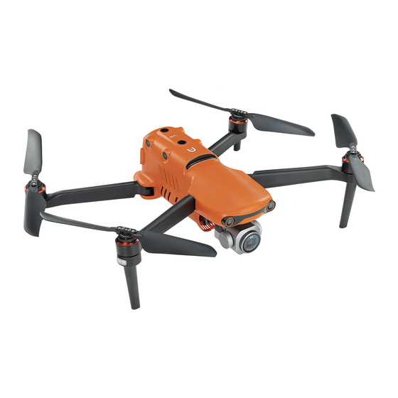
Product Overview Introduction The EVO II Pro V3 aircraft is a lightweight aircraft, integrated with a visual sensing system of 12 visual sensors for six directions, and has an omnidirectional obstacle avoidance capability. With an excellent power management system, the aircraft can reach a flight time of up to 40 minutes. -
Page 14: What's In The Rugged Case
After unboxing the product, please check whether the actual items match the items described in the following packing list and carefully inspect the appearance of the aircraft and all accessories. If anything missing or damage is found, please contact Autel Robotics After-Sales Support or authorized dealers promptly. -
Page 15: Uas Introduction
Chapter 1 Product Overview Table 1-1 Packing List Item Model/Specification Quantity Note Includes 1 battery, EVO II Pro V3 propellers, 1 gimbal MDCV3 aircraft camera, and a gimbal protective cover. Spare Smart XE3_7100_1155 Battery Autel Smart Controller SE Remote comes with 2 command Controller sticks and 2 antennas. - Page 16 Any damage or missing of these components may result in a malfunction. The Autel Explorer App, serving as the flight application software that controls the aircraft, should be maintained to ensure comprehensive control over the UAS.
- Page 17 Users can use accordingly. When the remote controller and the aircraft are frequency-paired and the remote controller is connected to the internet, Autel Explorer APP will automatically check for firmware updates. More instructions, please refer to “7.1 Aircraft and Remote Controller...
- Page 18 Chapter 1 Product Overview Google Pinyin Input 4.5.2.193126728-arm64-v8a System Software Android Keyboard System Software (AOSP) The pre-installed Apps mentioned are the basic application for the remote controller. Users also have the option to install third-party software if desired.
-
Page 19: Flight Safety
The EVO II Pro V3 aircraft is a light unmanned aircraft, and the operation of this product by individuals under the age of 18 is prohibited by Autel Robotics. -
Page 20: The U.s
This product is not a toy, and individuals under the age of 16 are prohibited from operating In the EU region, The EVO II Pro V3 aircraft belongs to the category of Level C2 UAV. When in use, it must comply with the operational restrictions of the A2 subcategory, specifically in urban environments: 1. -
Page 21: Other Countries And Regions
EASA Class 2 drones with low speed mode: (https://www.easa.europa.eu/document-library/general-publications/drones-information- notices) According to EU regulations, the EVO II Pro V3 aircraft is equipped with sensors (gimbal camera) capable of detecting personal data. Users are required to undergo legal registration when using the product. -
Page 22: Flight Environment Requirements
Chapter 2 Flight Safety Prohibit the use of the aircraft at large event venues, including but not limited to sports stadiums and concerts. Avoid flying in airspace exceeding the regulated altitude. Do not use the aircraft to carry any illegal hazardous materials. ... -
Page 23: Declaration Of Maximum Take-Off Mass
Chapter 2 Flight Safety Exercise caution when flying near electromagnetic interference sources and continuously monitor and assess the stability of the remote controller's video transmission signal and image. Common sources of electromagnetic interference include, but are not limited to, high-voltage transmission lines, high-voltage substations, mobile communication base stations, and TV broadcast signal towers. -
Page 24: Obstacle Avoidance System
Chapter 2 Flight Safety Recommended mounted area (bottom view) Recommended mounted location (not affecting the observation range) Note To keep the vision and the performance of the aircraft solid, it is recommended that when users are mounting payload, the mounting point should be located at the center line of the aircraft and should not be beyond the area bracketed in the fig 2-1. -
Page 25: Visual Positioning Function
The visual obstacle avoidance system is not 100% reliable. When flying with the visual obstacle avoidance system activated, always pay attention to the live video feed on the Autel Explorer App. Visual Positioning Function The aircraft supports visual positioning function in the absence of GNSS signals, providing flight positioning capabilities when GNSS signals are poor or lost, ensuring the safe flight of the aircraft. -
Page 26: Visual Obstacle Avoidance Function
If the aircraft is in ATTI mode: The Autel Explorer App will display a floating window with the alert "ATTI mode, fly with caution." and the remote controller will simultaneously emit a voice prompt. -
Page 27: Auto Return Home
“6.4 Setting Interface” in Chapter 6. If the return home point is not set in the Autel Explorer App, the aircraft will default to the takeoff point as the return home point. During the auto return home process, the control functions of the remote controller for the aircraft will be disabled. -
Page 28: Manual Activation Of Auto Return Home
If the current battery level is only sufficient for the return home process, the Autel Explorer App will display a pop-up alert saying "The system calculates that your current charge is only enough to return to the Home Point. -
Page 29: Auto Return Home Mechanism
4 seconds, the remote controller will display the message "Remote controller not connected to the aircraft," and the aircraft will activate the auto return home. During the execution of a flight mission, the default loss of connection behavior in the Autel Explorer App is set to "Continue Mission."... -
Page 30: Landing Protection Function
Rebuilding of the C2 link To ensure the safety and controllability of flight behavior, the EVO II Pro V3 aircraft will continuously attempt to reestablish the C2 link with the ground control station (remote controller) after losing the C2 link. In practice, this process is divided into the following stages:... -
Page 31: Flight Restrictions And Unlocking
The loss of connection behavior for the EVO II Pro V3 aircraft includes two modes: “Go home”, “Resume”. After losing the C2 link, the EVO II Pro V3 aircraft will display "Remote controller and the aircraft disconnected" warning message (in red) in the status notification bar of the Autel Explorer App, and the remote controller will simultaneously emit a voice prompt. -
Page 32: Restricted Zones
Chapter 2 Flight Safety update airspace restriction information, which will be synchronized to the drone. During flight, relevant airspace restriction information will be displayed in real-time on the Autel Explorer App to ensure the drone's safe and legal flight. Due to the inherent delay in information retrieval, the airspace restriction information of the geofence system may not completely align with the latest local laws and regulations. - Page 33 In the Autel Explorer App, tapping on each no-fly zone on the map will prompt the geofence information of each no-fly zone: No-fly zone: area name, area level (no-fly zone), affiliated area (prefecture-level city), no-fly time (only temporary no-fly zone display).
-
Page 34: Import Ugz
Operation method: Copy the JSON file to the root directory of the remote controller, enter the Intelligent Photo mode, on the map interface of the Autel Explorer App, tap " " >... -
Page 35: Unlocking No-Fly Zones
(with the take-off point as the center). Users can set the altitude and distance limits in the Autel Explorer App to ensure the safe flight of the aircraft. For more details, please refer to “6.4 Settings... -
Page 36: Aircraft Calibration
Chapter 2 Flight Safety Altitude and Distance Limitation Diagram In the Autel Explorer App, the allowable range for altitude restriction is 30 ~ 800 m, and the allowable range for distance restriction is 30 ~ 5000 m. During actual flight, the set... - Page 37 Chapter 2 Flight Safety Please stay away from strong magnetic field areas or large pieces of metal during calibration, such as magnetic ore, parking lots, construction areas with underground steel bars, near underground or overhead power transmission lines, etc. ...
-
Page 38: Imu Calibration
However, if there are abnormal acceleration and angular velocity readings, follow the steps below for IMU calibration. Follow the prompts on the IMU calibration page in the Autel Explorer App to position the aircraft and ensure it remains in a stationary state. - Page 39 Chapter 2 Flight Safety The gimbal will be inactive during the IMU calibration process. Table 2-5 IMU Calibration Step Operation Diagram After turning on the aircraft and remote control, tap " " > "Flight Control" > "IMU Calibration" > "Start Calibration"...
- Page 40 Chapter 2 Flight Safety Place the left side of the aircraft flat on the ground until the App prompts you to proceed to the next step. Place the right side of the aircraft flat on the ground until the App prompts you to proceed to the next step.
-
Page 41: Gimbal Auto Calibration
Place the aircraft on a flat surface, and after turning on both the aircraft and the remote control, keep the aircraft in a stationary state. On the flight page of the Autel Explorer App, tap " " > "Gimbal" > "Gimbal Auto Calibration" > "Start Calibration"... -
Page 42: Direct Remote Identification
The EVO II Pro V3 aircraft supports the DRI system and uses Wi-Fi (Wi-Fi Beacon, 802.11n) for broadcasting. Enable the DRI system by configuring it in the Autel Explorer App. -
Page 43: Basic Flight Procedure
Address all warnings and errors displayed on the Autel Explorer App. Enter the Autel Explorer App settings page to configure flight control parameters, obstacle avoidance systems, joystick modes, and other relevant flight safety parameters. Familiarize yourself with flight operations to ensure parameter settings meet your needs and guarantee flight safety. -
Page 44: List Of Safeguard
Chapter 2 Flight Safety List of Safeguard Before flight, please know the following safeguard information, which helps you handle abnormal situations in a correct and safe way. Table 2-7 List of Safeguard Safety Function Refer To Auto Return Home “2.7 Auto Return Home”... -
Page 45: Aircraft
Aircraft Aircraft Activation When unboxing the product for the first time, you need to activate the EVO II Pro V3 aircraft before using it. By default, the aircraft is pre-paired with the remote controller at the factory. After turning on the aircraft and the remote controller, you will see an activation prompt in the Autel Explorer App. - Page 46 Chapter 3 Aircraft Integrates wide-angle camera for stable shooting or Gimbal Camera measurements during flight. Aircraft Rear View Table 3-2 Aircraft Rear View Details Name Description Press and hold the power button for 3 seconds to start the Power button aircraft.
- Page 47 Chapter 3 Aircraft Aircraft Right View Table 3-4 Aircraft Right View Details Name Description Right Visual Used to sense the obstacles in the Right and avoid the aircraft Sensing System from colliding with them. Smart Battery Used to provide energy for aircraft operation. Heat Dissipation An opening for expelling the heat generated during the flight of Vent...
- Page 48 Chapter 3 Aircraft Aircraft Top View Table 3-5 Aircraft Top View Details Name Description Upward Visual Used to sense obstacles above, and to the left and right of the Sensing System aircraft and avoid collisions. Aircraft Down View Table 3-6 Aircraft Down View Details Name Description Used to sense obstacles beneath the aircraft, avoiding...
-
Page 49: Propeller
Propeller Propellers are wearable parts that require regular maintenance and replacement to ensure the safe flight of the aircraft. The EVO II Pro V3 aircraft uses a quick-release propeller design, making it easy for you to replace them. Replacing Propellers The propellers are installed in the aircraft by default at the factory, and reinstallation is not required. - Page 50 Chapter 3 Aircraft Detaching the Propellers 1. Press and hold the smart battery power button for 3 seconds to power off the aircraft. 2. First hold the motor on the arm below the propeller to prevent it from rotating, press down on the propeller center shaft firmly, and then turn it in the unlocking direction to detach the propeller.
-
Page 51: Storing Propellers
Before each flight, make sure that all propellers are mounted correctly and securely. Please use the propellers provided by Autel Robotics. Do not mix propellers of different models. - Page 52 Chapter 3 Aircraft Arm Light Table 3-8 Arm Light Status Details Mode Front Arm Light Rear Arm Light During normal flight, will During normal flight, the green alternate flashing according to a GNSS Mode light will flash slowly in cycles of cycle of (green light on for 1s /red ATTI Mode (1s on/1s off) to distinguish the...
-
Page 53: Auxiliary Bottom Light
You can manually turn the bottom LED auxiliary lights on or off in the Autel Explorer App. Auxiliary Light ... -
Page 54: Camera
3 meters above the ground when the aircraft is landing and the ambient light is insufficient, and they will turn off automatically after a successful landing. Camera The EVO II Pro V3 aircraft is equipped with a 6K optical gimbal camera, providing high-definition visible light photography capabilities. Camera Structure... -
Page 55: Gimbal
“6.7 Camera Interface” in Chapter 6. Gimbal The EVO II Pro V3 aircraft is equipped with a three-axis stabilized gimbal with a high-precision motor structure, which can ensure stable camera shooting when the aircraft is flying. Gimbal Structure Table 3-12 Gimbal Structure Details... -
Page 56: Gimbal Mechanical Rotation Range
The mechanical rotation ranges of the pitch, yaw, and roll axes of the gimbal are shown below. Table 3-13 Mechanical Rotation Range of the Gimbal of the EVO II Pro V3 Aircraft You can control the rotation range of the gimbal, pitch: -90° to 30°, Roll: -90°~90°. -
Page 57: Replacing The Gimbal
Replacing the Gimbal EVO II Pro V3 aircraft has a removable gimbal design, allowing you to easily replace the gimbal to meet your flight needs in various scenarios. Please follow the instructions below to replace the gimbal, as improper replacement may cause damage to the gimbal or poor contact with the gimbal interface. - Page 58 Chapter 3 Aircraft Removing the Gimbal 1. Place the aircraft on a horizontal surface with the bottom of the fuselage facing up. 2. Use the screwdriver with T6 specification to loosen the two anti-loosening screws securing the "Connector Protective Cover." and remove the "Connector Protective Cover." 3.
-
Page 59: Flight Control System
Flight Control System EVO II Pro V3 aircraft achieves stable and convenient flight control through its built-in intelligent flight control system. The system supports a number of advanced functions, including auto- return, failsafe, visual positioning system, etc. -
Page 60: Flight Modes
Flight Modes The aircraft has varying flight performance in different flight modes. You can set the flight mode of the aircraft in the Autel Explorer App. For more information, please refer to “6.3 Status Bar”... -
Page 61: Intelligent Flight Function
Chapter 3 Aircraft When switching to Ludicrous mode, its flight speed is greatly improved compared with Standard mode, so the braking distance in this mode will be correspondingly extended. You should maintain a braking distance of at least 50 meters when operating the aircraft in this mode to ensure personal and flight safety. -
Page 62: Connecting To Pc/Mac
Chapter 3 Aircraft install microSD card The aircraft has built-in 8 GB storage space, with approximately 6 GB available due to system firmware and app updates. It is recommended that you prioritize using an external microSD card for storing the image data collected during flight to avoid running out of internal storage space, which will affect the flight safety of the aircraft. -
Page 63: The Noise Description
Chapter 3 Aircraft The Noise Description When the EVO II Pro V3 aircraft hovers, it generates noise with an intensity of 69dB (at a distance of 0.5 meters from the aircraft). Users should familiarize themselves with local noise pollution prevention and control regulations, and set a reasonable flight altitude or safety distance to ensure no interference with other individuals, groups, or organizations. -
Page 64: Autel Skylink Image Transmission Function
Chapter 3 Aircraft Autel SkyLink Image Transmission Function The EVO II Pro V3 aircraft is equipped with Autel SkyLink 2.0 transmission technology, featuring two transmission antennas, where one transmits signals, and the other receives signals. This allows for a communication range of up to 15 kilometers between the aircraft and ground equipment. - Page 65 Chapter 3 Aircraft Table 3-18 Global Certified Frequency Bands for EVO II Pro V3 Aircraft (Image Transmission) Operating Certified Details Bandwidth Frequency Countries & Regions BW=1.4MHz USA 900M 902 – 928MHz BW=10MHz Canada BW=20MHz BW=1.4MHz ...
- Page 66 Supplementary Information Standard configuration The Autel Smart Controller SE is included as a standard item in the aircraft package, and Autel Robotics also provides retail packaging for customers to choose independently. Ensure that the control software version meets the above requirements when remotely...
-
Page 67: Remote Controller
Remote Controller Introduction The Autel Smart Controller SE is installed with the Autel Explorer App by default, allowing you to operate and set the aircraft and the gimbal camera and transmit high-definition videos from the gimbal camera in real time. It offers a maximum communication distance of 15 kilometers. - Page 68 Chapter 4 Remote Controller information, please refer to “6.4 Settings Interface” in Chapter Use the Autel Explorer App to customize the key function. For C Button more information, please refer to “6.4 Settings Interface” in Chapter 6. Left Dial Wheel Turn the dial wheel to adjust the gimbal pitch.
- Page 69 Chapter 4 Remote Controller Remote Controller Front View Table 4-2 Remote Controller Front View Details Name Description Transmits the control signals of the remote controller and Antenna receives the image transmission information of the aircraft. Receives information from an external audio source near the Audio Input remote controller.
-
Page 70: Communication Frequency Bands
Communication Frequency Bands The image transmission frequency bands of Autel Smart Controller SE comply with regulatory requirements worldwide. Please refer to the table below for the relevant certified frequency bands. - Page 71 After the aircraft is paired with the remote controller, the frequency bands between them will be automatically controlled by the Autel Explorer App based on the geographical information of the aircraft. This is to ensure compliance with local regulations regarding frequency bands.
-
Page 72: Installing The Remote Controller Lanyard
Chapter 4 Remote Controller Australia Korea Table 4-5 Global Certified Frequency Bands (Wi-Fi) Operating Frequency Details Certified Countries & Regions 2.4G 802.11b/g/n Chinese Mainland (2400 – 2476 MHz) Taiwan, China United States Canada 2.4G ... -
Page 73: Installing/Storing Command Sticks
2. Wear the lanyard around your neck, and adjust it to a suitable length. Installing/Storing Command Sticks The Autel Smart Controller SE features removable command sticks, which effectively reduce storage space and enable easy carrying and transportation. Installing command sticks Take out the command sticks from the command stick storage slots. - Page 74 Chapter 4 Remote Controller Turning the Remote Controller On When using a brand-new remote controller for the first time, please follow the on-screen instructions to complete the relevant setup. Turning the Remote Controller Off When the remote controller is on, press and hold the power button at the right side of the remote controller until the "Off"...
-
Page 75: Checking The Battery Level Of The Remote Controller
When the remote controller is on, you can check the current battery level of the remote controller in the following ways: Check it on the top status bar of the Autel Explorer App. Check it on the system status bar of the remote controller. In this case, you need to enable “Battery Percentage”... -
Page 76: Charging The Remote Controller
240 V~ 50/60 Hz). Use the RC charger to charge the remote controller Please use the official charger provided by Autel Robotics to charge the remote controller. Using third-party chargers may damage the battery of the remote controller. After charging is complete, please disconnect the remote controller from the charging device promptly. -
Page 77: Remote Controller System Interfaces
After the remote controller is turned on, it enters the main interface of the Autel Explorer App by default. In the main interface of the Autel Explorer App, slide down from the top of the touch screen or slide up from the bottom of the touch screen to display the system status notification bar and navigation keys, and tap the "Home"... - Page 78 Chapter 4 Remote Controller Remote Controller Main Interface Table 4-7 Remote Controller Main Interface Details Name Description Time Indicates the current system time. Battery Status Indicates the current battery status of the remote controller. Indicates that Wi-Fi is currently connected. If not connected, the icon is not displayed.
- Page 79 Chapter 4 Remote Controller Flight software. The Autel Explorer App starts by default when Autel Explorer the remote controller is turned on. For more information, please refer to “Chapter 6 Autel Explorer App”. “Back” Button Tap the button to return to the previous page.
-
Page 80: Shortcut Menu
Quickstep √ Android 11 Please be aware that the factory version of the Autel Explorer App may vary depending on subsequent function upgrades. Shortcut Menu Slide down from anywhere on the "Remote Controller Interface", or slide down from the top of the screen in any app to display the system status notification bar, and then slide down again to bring up the “Shortcut Menu”. -
Page 81: Frequency Pairing With The Remote Controller
Frequency Pairing With the Remote Controller Using the Autel Explorer App Only after the remote controller and the aircraft are paired can you operate the aircraft using the remote controller. Table 4-10 Frequency Pairing Process in the Autel Explorer App Step Operation Diagram Turn on the remote controller and the aircraft. -
Page 82: Using Combination Buttons (For Forced Frequency Pairing)
Chapter 4 Remote Controller The aircraft included in the aircraft kit is paired with the remote controller provided in the kit at the factory. No pairing is required after the aircraft is powered on. Normally, after completing the aircraft activation process, you can directly use the remote controller to operate the aircraft. - Page 83 Chapter 4 Remote Controller Mode 1 Mode 1 Table 4-11 Mode 1 Details Stick Move Up/Down Move Left/Right Left Controls the forward and backward Command Controls the heading of the aircraft movement of the aircraft Stick Right Controls the ascent and descent of Controls the left or right movement Command the aircraft...
-
Page 84: Setting Stick Mode
Chapter 4 Remote Controller Right Controls the forward and backward Controls the left or right movement Command movement of the aircraft of the aircraft Stick Mode 3 Mode 3 Table 4-13 Mode 3 Details Stick Move Up/Down Move Left/Right Left Controls the forward and backward Controls the left or right movement... - Page 85 Chapter 4 Remote Controller Table 4-14 Default Control Mode (Mode 2) Mode 2 Aircraft Flight Status Control Method Left Command The up-and-down direction of the left stick Stick is the throttle stick, which is used to control Move Up or the vertical lift of the aircraft.
-
Page 86: Starting/Stopping The Aircraft Motor
Chapter 4 Remote Controller Right Command The left-and-right direction of the right stick Stick is the roll stick, which is used to control the Move Left or flight of the aircraft in the left and right Right directions. Push the stick to the left, and the aircraft will tilt to the left and fly to the left of the nose;... -
Page 87: Remote Controller Keys
Chapter 4 Remote Controller sticks inward or outward, as shown in the figure, until the motor stops. When taking off and landing the aircraft, stay away from people, vehicles, and other moving objects. The aircraft will initiate a forced landing in case of sensor anomalies or critically low battery levels. -
Page 88: Take-Off/Return-To-Home Button And Pause Button
“6.4 Settings Before using the auto-return function, you need to set the home point in advance in the Autel Explorer App. For more information, please refer to Interface” in Chapter 6. If the home point is not set, the aircraft will take the take-off point as the home point by default. -
Page 89: Turning On/Off The Remote Controller Prompt Sound
Table 4-17 Calibrating the Remote Controller Step Operation Diagram Turn on the remote controller. After entering the main interface of the Autel Explorer App, tap “ ” in the upper-right corner, select "Remote Control", and then tap "Remote Control Calibration". Follow the on-screen instructions to... -
Page 90: Hdmi Screen Output
Chapter 4 Remote Controller Calibration of the dials and command sticks: According to the calibration guide page of the remote controller, move the left and right dial wheels and the left and right sticks according to the directions shown in the figure and hold for 1 second. -
Page 91: Smart Battery
Smart Battery Battery Introduction The EVO II Pro V3 aircraft comes standard with the XE3_7100_1155 smart battery (hereafter referred to as smart battery) as the power battery. This battery is a rechargeable lithium-ion polymer (LiPo) battery and features high energy density and capacity. The smart battery can be charged with an XA3_1320 battery charger. -
Page 92: Smart Battery Functions
60% (by default) and the discharge process takes 2-3 days. Users can set the start discharge time in the Autel Explorer App. Although the battery has no indication of a self-discharge cycle, you may notice that the battery is slightly warm, which is normal. -
Page 93: Smart Battery Usage
Chapter 5 Smart Battery Short Circuit Protection Once a short circuit is detected, the power supply of the smart battery will be cut off to protect the battery. Before using the smart battery, please carefully read and strictly follow the requirements in this Manual, “Battery Safety Operation Guidelines”, and “Disclaimer”, and those on the battery's surface sticker. -
Page 94: Turning On/Off The Smart Battery
Chapter 5 Smart Battery Slowly insert the smart battery into the battery compartment on the aircraft fuselage, and you will hear a clicking sound when the battery is in place. If the smart battery is not installed properly, it may cause the battery to fall off during the flight, damage the aircraft, or even cause personal injury. -
Page 95: Checking Battery Level
Chapter 5 Smart Battery Turning Off the Smart Battery When the smart battery is turned on, press and hold the power button for 3 seconds to turn off the battery. Turn On or Off the Smart Battery If the smart battery is not installed in the aircraft, it is not recommended to turn on/off the battery, and attention should be paid to insulation protection at the battery connector. -
Page 96: Charging The Smart Battery
After the aircraft is connected to the remote controller, you can check the current smart battery level of the aircraft in the top status bar or on the "Aircraft Battery" page of the Autel Explorer App. For more information, please refer to “6.3 Status Bar”... - Page 97 Modifying the official smart battery or charging device provided by Autel Robotics is prohibited. Only use the battery and charging device provided by Autel Robotics. Autel Robotics is not responsible for any consequences, such as battery accidents and flight failure, caused by the use of third-party batteries or charging devices.
-
Page 98: Storing And Transporting The Smart Battery
Occasionally, there are situations that affect the lifespan of the smart battery. In this case, you can try maintenance and repair. The Autel Explorer App reminds you when the smart battery needs maintenance. The following battery maintenance check items are available for the smart battery:... -
Page 99: Standard Charging And Discharging Process
2. Insert the smart battery into the aircraft and turn on the power. Check the battery information through the Autel Explorer App, whether the voltage difference between the battery cells is less than 0.1 V, and whether the battery firmware is up to date. -
Page 100: Autel Explorer App
The software integrates a variety of professional functions, which is easy to improve efficiency. Through a variety of built-in intelligent flight functions, the aircraft can be highly intelligent operation, enabling industrial applications. Please be aware that some UI interfaces of Autel Explorer App may be different due to version updates. Main Interface After Smart Controller pair with the aircraft, Autel Explorer App will automatically enter the main interface. -
Page 101: Status Bar
Prompts how to pair between the aircraft and the remote Connection Wizard controller. Status Bar Status Bar of the Autel Explorer App Table 6-2 Details of the Status Bar of the Autel Explorer App Icon Icon description description Tap this icon to enter the main interface of the Home Page Autel Explorer App. -
Page 102: Settings Interface
Tap this icon to enter the "Settings" interface. Settings Interface On the flight page of the Autel Explorer App, tap the " " icon to enter the Settings interface. In the "Settings" interface, users can set the parameters of Flight control, Visual Navigation, Remote control, Image transmission, Aircraft battery, Gimbal, Live broadcast, Data security and General parameters and so on. - Page 103 Chapter 6 Autel Explorer App Set the return altitude of the aircraft, the setting range is 25-800 meters. Set the aircraft acceleration mode (flight gear) to "Standard" or "Ludicrous", and select the corresponding maximum speed limit. Set the maximum flight altitude limit of the aircraft, the setting range is 30-800 meters.
-
Page 104: Operating Mode
Operating Mode Autel Explorer App supports two operating modes: "Camera" mode and "Mission" mode. Each type of operating mode has different mission scenarios. Users can select a operating mode from the Autel Explorer App main interface, or tap the "... - Page 105 Chapter 6 Autel Explorer App Waypoint Rectangular Polygon “Mission” Oblique Recording Slope Before selecting "Mission" mode, please ensure that the aircraft's GNSS signal is good, otherwise the aircraft will not be able to take off and perform the mission.
-
Page 106: Map Interface
Chapter 6 Autel Explorer App the Mission scenario selection page of the "Mission" mode Map Interface Users can plan routes or observe aircraft flight trajectories on the map interface. In "Camera" and "Mission" modes, the map interface and camera interface can be switched back and forth. -
Page 107: Camera Interface
Chapter 6 Autel Explorer App Table 6-5 Details of the Map Interface Name Description Tap this icon to switch the style of displaying the device's Orientation display orientation information, and support real-time display of the aircraft's flight altitude, flight distance, and flight speed. -
Page 108: Mission
Chapter 6 Autel Explorer App Table 6-6 Details of the Camera Interface Name Description live streaming Tap this icon to enable the live broadcast function. Tap this icon to view the materials in the aircraft album and photo album local album and download or delete them. - Page 109 Chapter 6 Autel Explorer App Waypoint Mission Page After completing the mission editing, tap the " " icon on the right side of the page to perform a pre-flight check. After confirming that it is normal, you can perform the automatic flight mission.
-
Page 110: Firmware Updates And Maintenance
5. Restart the remote controller and aircraft after upgrading. Method 2 When the system detects a new firmware version, the Autel Explorer App will automatically pop up a prompt box after connecting to the aircraft to remind you to download and install it. Please follow the prompts to download and upgrade. -
Page 111: Aircraft Parts Maintenance
To ensure that the aircraft maintains optimal performance, all parts of the aircraft need to be maintained regularly. For details, please refer to the Maintenance Manual. If you have any questions, please contact Autel Robotics. Table 7-1 Aircraft consumable parts list... -
Page 112: Troubleshooting Guide
Users can contact Autel Robotics to purchase the above parts and replace them by themselves according to the operating instructions. If you need to replace parts that are not in the list, please contact Autel Robotics. Damage caused by unauthorized disassembly and assembly will not be covered by the warranty. - Page 113 16. When the aircraft or the controller experiences unexpected shutdown during firmware updates, restart the device: If it can power on normally, make sure that the device is sufficiently charged before proceeding with the update; If the device cannot power on, contact Autel Robotics.
- Page 114 Chapter 7 Firmware Updates and Maintenance 17. For the purpose of device safety, please do not use unknown USB device or other external devices.
-
Page 115: Appendix A Product Specifications
Appendix A Product Specifications Appendix A Product Specifications A.1 Aircraft Aircraft Weight 1191 g (With propellers, battery) Maximum takeoff weight 1270 g Folded: 230×130×108mm Dimensions Unfolded: 457×558×108mm Max. rotation speed 9000 rpm Wheelbase 397 mm Novice mode:3 m/s Maximum ascent speed Standard: 5m/s Ludicrous: 8 m/s Novice mode: 3 m/s... - Page 116 Appendix A Product Specifications Working temperature -10~40℃ Battery hot replacement not support Internal storage Onboard storage: 8GB GNSS GPS/Galileo/BeiDou/GLONASS Vertically: ±0.1 meters (when visual positioning is working normally) ±0.5 meters ( when GNSS is working normally) Hover accuracy Horizontally: ±0. 3 meters (when visual positioning is working normally) ±...
-
Page 117: A.2 Gimbal Camera
Appendix A Product Specifications Upward: 0.5~10 meters Effective sensing speed:<5m/s Downward: 0.5~10 meters Effective sensing speed:<5m/s Forward and backward: 60° horizontally, 80° vertically Upward: 65° horizontally, 50° vertically Left and right: 65° horizontally, 50° vertically Downward: 100° horizontally, 80° vertically Front, rear, left and right:The surface has rich texture and sufficient lighting conditions ( >15 lux, normal indoor fluorescent lighting environment) -
Page 118: A.3 Remote Controller
Heading: -90° to +90° Stable system Three-axis stabilization Maximum control speed (pitch) 300°/s Angualr vibration range 0.005° A.3 Remote Controller Autel Smart Controller SE Material PC+ABS 226.3×137.7×31.5 mm (antennas folded) Dimensions 226.3×215.4×31.5 mm (antennas unfolded) Weight 617 g Operating Temperature -10℃... - Page 119 Appendix A Product Specifications Protection Rating IP43 Internal Storage 128GB microSD Extension Supported Operating System Based on Android 11 Application Installation Supports the installation of third-party Android apps HDMI Outputs up to 1080P@60FPS video USB-C Charging: supports PD/QC fast charging, up to 65W USB-A USB2.0 GNSS...
- Page 120 Appendix A Product Specifications 2.4G: 2.400 – 2.476GHz**, 2.400 – 2.4835 GHz 5.7G: 5.65 - 5.755 GHz*** 5.8G: 5.725 - 5.829GHz**, 5.725 - 5.850 GHz * Only applicable to FCC regions. **Only applicable to SRRC regions. *** Only applicable to MIC regions. Note: Some frequencies are only available in some regions or for indoor use only.
-
Page 121: A.4 Smart Battery
Appendix A Product Specifications 3.0 hours (50% brightness) Battery Replacement Supported A.4 Smart battery Smart Battery XE3_7100_1155 Operating Temperature 0~+45℃ Battery Type LiPo 3S Rated Capacity 7100 mAh Battery energy 82 Wh Voltage 11.55 V Charging Voltage Limit 13.2V Rated Charging Power Maximum charging power Weight 365g... -
Page 122: Appendix B Declaration Of Conformity (Doc)
601,701,801,901, Block B1, Nanshan iPark, No. 1001 Xueyuan Avenue, Nanshan District, Shenzhen, Guangdong, 518055, China We, Autel Robotics Co., Ltd., declare under our sole responsibility that the above referenced product is in conformity with the applicable requirements of the following directives:... - Page 123 The notified body, LGAI Technological Center S.A./Applus, notified body number: 0370, performed the EU-type examination in according with Annex III, Module B of Regulation (EU) 945/2019, and issued the EU-type examination certificate: XXX. Signed for and on behalf of: Autel Robotics Co., Ltd. Place: Shenzhen, China Date: 2024-01-13...
-
Page 124: Appendix C Drone Pilot Information Notice
Appendix C Drone Pilot Information Notice Appendix C Drone Pilot Information Notice When flying this aircraft product in the territory of EU Member States, please comply with the following EASA regulations. - Page 125 Appendix C Drone Pilot Information Notice You can visit the EASA official website to get other language versions: https://www.easa.europa.eu/en/document-library/general-publications/drones-information- notices.
Need help?
Do you have a question about the EVO II Pro V3 and is the answer not in the manual?
Questions and answers