Grundfos CU 3X2 Installation And Operating Instructions Manual
Hide thumbs
Also See for CU 3X2:
- Instructions manual (40 pages) ,
- Installation and operating instructions manual (23 pages) ,
- Instructions manual (18 pages)

Related Manuals for Grundfos CU 3X2


Summary of Contents for Grundfos CU 3X2
- Page 1 GRUNDFOS INSTRUCTIONS CU 3X2, CU 3X4 Installation and operating instructions CU 3X2, CU 3X4 Installation and operating instructions Other languages http://net.grundfos.com/qr/i/96842987...
- Page 3 CU 3X2, CU 3X4 English (GB) Installation and operating instructions ........4 Appendix A .
-
Page 4: Table Of Contents
Service ....19 Replacing the CU 3X2 ... . 19 13.1 Replacing the CIM module ..19... -
Page 5: General Information
Observe these instructions for explosion- proof products. 1.1 Hazard statements The symbols and hazard statements below may appear in Grundfos installation and operating A blue or grey circle with a white graphical instructions, safety instructions and service symbol indicates that an action must be instructions. -
Page 6: Product Description
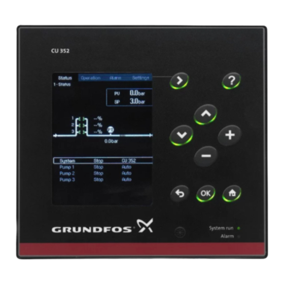
2. Product description CU 362 The CU 3X2 is a flexible control unit for control and monitor of up to six pumps. In the following sections, two variants are described: • CU 352 water supply and booster systems heating and air-conditioning systems. -
Page 7: Indicator Lights
2.1 Indicator lights 2.3 Potentially explosive environments The CU 3X2 has a green and a red indicator light. The CU 3X2 must not be installed in explosive environments, but may be used together with The green indicator light shows that the power supply Grundfos pumps approved for installation in is switched on. -
Page 8: Identification
3. Identification 4. Installation preparation The CU 3X2 can be identified by the nameplate on The CU 3X2 is only intended for control panels. the back. Before installation, check the following: • The CU 3X2 corresponds to the order. •... -
Page 9: Location
USA and Canada (branch circuit USA and Canada protection): Use a UL/CSA-listed non- The CU 3X2 is type 3R when mounted on the front of time delay, class-rated Branch Circuit a cabinet with type rating 1, 2, 3, 3R, 5, 12, 12K or... -
Page 10: Security
If a firewall or private network is not in place, the Grundfos host product may be subject to a cybersecurity risk and becomes vulnerable to an attack or compromise. -
Page 11: Mechanical Installation
5. Mechanical installation 6. EMC-correct installation Fasten the CU 3X2 with the four screws (M5 x 10) The CU 3X2 is mounted in a panel which also supplied with the unit (pos. 1). contains an IO 351 module, contactors and other power equipment. -
Page 12: Internal Genibus Connection
The module type and the number of modules depend on the application software. 6.2 Fieldbus communication interface modules The CU 3X2 can be connected to an external communication network through an add-on Communication Interface Module (CIM). The CIM modules must be ordered separately. -
Page 13: Fitting The Cim Module
6.3 Fitting the CIM module 2. Open the back cover and break off the tap. WARNING Electric shock Death or serious personal injury ‐ Switch off the power supply to the CU 3X2 before fitting the CIM module. The CIM module must be fitted by an authorised person. -
Page 14: Startup
During transportation: -20 to +60 °C. At temperatures below 0 °C, the display may react slowly. Relative air humidity 5. Refit the back cover to the CU 3X2 and secure it with the mounting screw. 5 to 95 %. Enclosure class IP54 from the front of the module. -
Page 15: Electrical Data
9. Electrical data 9.8 Digital outputs (relay outputs) 9.1 Supply voltage Normally open contacts C, NO 1 × 100-240 VAC ± 10 %, 50/60 Hz, PE Maximum contact load 240 VAC, 2 A (Class 1 equipment). Minimum contact load 5 VDC, 10 mA Overvoltage category II. -
Page 16: Battery Backup (Ups)
9.11 Battery backup (UPS) 9.12 Terminal groups A battery can be connected to the CU 3X2 as backup for the normal power supply. The battery can be connected directly to the CU 3X2 without a fuse. With the backup battery, the CU 3X2 can continue to operate despite interruptions in the normal power supply. -
Page 17: Overview Of Inputs And Outputs
C: Common. Position numbers, see fig. Terminal groups. Group Terminal Designation Data Diagram Connection to phase CU 3X2 conductor 1 × 100-240 VAC ± 10 %, 50/60 Hz Connection to neutral conductor Connection to protective earth RS-485 A CU 3X2... - Page 18 Group Terminal Designation Data Diagram Supply to sensor. Short-circuit- +24 V protected 30 mA. Supply to sensor. Short-circuit- +24 V protected 30 mA. Input for analog signal, 0-20/4-20 mA or 0-10 V Supply to sensor. Short-circuit- +24 V protected 30 mA. Input for analog signal, 0-20/4-20 mA or 0-10 V All terminals (except for mains terminals) must only be connected to voltages...
-
Page 19: Maintenance
5. Remove the CU 3X2 from the panel/cabinet. 6. Fit the new unit as described. 7. Connect all conductors according to markings. 8. Configure the new CU 3X2 with a PC Tool. See the service instructions. Related information 5. Mechanical installation 13.1 Replacing the CIM module... -
Page 20: Original Installation And Operating Instructions 14. Fault Finding
14. Fault finding WARNING Electric shock Death or serious personal injury ‐ Before making any connections in pumps or the control cabinet, make sure that the power supply is switched off for at least 5 minutes and it cannot be switched on unintentionally. 14.1 Alarm and warning codes 14.1.1 Code 1 ( Leakage current ) •... - Page 21 14.1.4 Code 4 ( Too many restarts ) • Code 4 is shown on the display. • Origin of the alert: MP 204. Cause Remedy The pump is blocked or partly blocked that causes • Remove the blockage from the pump, pipes, or motor overload.
- Page 22 Origin of the alert: CU 362. Cause Remedy The pump requires service in regular intervals. • Contact Grundfos or an authorised service workshop. • Enable service countdown with Grundfos GO Remote: Settings > Service. 14.1.10 Code 15 ( SCADA callback error ) •...
- Page 23 Moisture switch is activated. Moisture is detected in • The pump or the motor needs overhaul. the motor. • Contact Grundfos. 14.1.18 Code 24 ( Vibration ) • Code 24 is shown on the display. • Origin of the alert: IO 113.
- Page 24 The IO terminal is configured incorrectly. • Select the IO terminal that needs to be changed in Grundfos GO Remote and adjust the configuration. 14.1.20 Code 26 ( Load continues even if motor is off ) • Code 26 is shown on the display.
- Page 25 14.1.23 Code 32 ( Overvoltage ) • Code 32 is shown on the display. • Origin of the alert: MP 204/CUE. Cause Remedy Voltage is too high. • Voltage on 1 or multiple phases is too high. Check the incoming voltage. 14.1.24 Code 33 ( Soon time for service (general service information) ) •...
- Page 26 14.1.27 Code 37 ( Suction valve leakage ) • Code 37 is shown on the display. • Origin of the alert: dosing pump. Cause Remedy Suction valve leaks in the dosing pump. • Check the valve and tighten it up. •...
- Page 27 14.1.31 Code 48 ( Overload ) • Code 48 is shown on the display. • Origin of the alert: AI/MP 204/CUE. Cause Remedy The pump is clogged, which causes the motor current • Remove the blockage. to increase. This may cause damage to the pump. •...
- Page 28 Cause Remedy The measured current is below the minimum. • Make sure that the nominal pump current is configured correctly in Grundfos GO Remote. • Make sure that the pump is connected to the pump terminals on the product. •...
- Page 29 Origin of the alert: CU 362/IO 351/IO 113/MP 204. Cause Remedy Possible hardware fault. • Power cycle the mains supply. If the fault still exists, check each module individually. Replace the controller or the module if possible. • Contact Grundfos or an authorised service workshop.
- Page 30 Internal communication fault. • Power cycle the controller. If the fault still exists, replace the controller. • Contact Grundfos or an authorised service workshop. 14.1.44 Code 77 ( Communication fault, twin-head pump ) • Code 77 is shown on the display.
- Page 31 14.1.48 Code 91 ( Fault, temperature sensor ) • Code 91 is shown on the display. • Origin of the alert: CUE. Cause Remedy Signal fault of the temperature sensor 1 on CUE • Check the sensor and the connections on the CUE drive.
- Page 32 14.1.53 Code 112 ( cos φ too high ) • Code 112 is shown on the display. • Origin of the alert: MP 204. Cause Remedy Maximum cos phi threshold is exceeded. • Consider the settings. • Check the pump, valves or pipes for blockage. 14.1.54 Code 113 ( cos φ...
- Page 33 14.1.58 Code 145 ( Temperature, upper bearing ) • Code 145 is shown on the display. • Origin of the alert: IO 113. Cause Remedy Support bearing temperature threshold is exceeded. • Overhaul the motor if possible. 14.1.59 Code 146 ( Temperature, lower bearing ) •...
- Page 34 • Ensure that the module, including the cables, is fitted correctly. The CIM module is defective. • Contact Grundfos. 14.1.64 Code 160 (CIM card fault) • Code 160 is shown on the display. • Origin of the alert: add-on CIM card.
- Page 35 14.1.67 Code 169 ( Signal fault, flow sensor ) • Code 169 is shown on the display. • Origin of the alert: CU 362 AI. Cause Remedy Sensor signal fault. • Check the sensor signal. • Replace the sensor. 14.1.68 Code 170 ( Signal fault, water-in-oil (WIO) sensor ) •...
- Page 36 PTC2 terminal A and B. Make sure that the error is eliminated. • Replace the product due to damaged PTC circuit. Contact Grundfos. 14.1.74 Code 186 ( Power meter ) • Code 186 is shown on the display. •...
- Page 37 • Check and configure the sensor start level. The pump is unable to remove the water. • Contact Grundfos or an authorised service workshop. The level sensor is defective and not reacting on level • Check the functionality of the level sensor.
- Page 38 14.1.81 Code 206 ( Water shortage, level 1 ) • Code 206 is shown on the display. • Origin of the alert: dosing pump. Cause Remedy Pre-empty tank. • Check the level in the pre-empty tank. 14.1.82 Code 208 ( Cavitation ) •...
- Page 39 Origin of the alert: CU 362 DI. Cause Remedy The contactor has reached its maximum number • Contact Grundfos. of operating cycles and is worn out. Alarm: The contactor is worn out and the pump cannot start. The contactor is approaching its maximum number •...
- Page 40 The connection to GENIbus is missing. • Check the connection cable of the GENIbus. The pump module is defective. • Contact Grundfos. 14.1.91 Code 226 ( GENIbus fault ) • Code 226 is shown on the display. • Origin of the alert: IO 351.
- Page 41 14.1.93 Code 228 ( Other alarm ) • Code 228 is shown on the display. • Origin of the alert: CU 362 DI. Cause Remedy External flowmeter high flow alarm is active. • Check the external flowmeter. 14.1.94 Code 229 ( Water on floor ) •...
- Page 42 14.1.98 Code 240 ( Lubricate bearings (service information) ) • Code 240 is shown on the display. • Origin of the alert: CUE. Cause Remedy CUE reported to lubricate bearings. • Check the local alarms and instructions on the CUE. 14.1.99 Code 241 ( Phase error ) •...
- Page 43 14.1.103 Code 246 ( User-defined relay output activated ) • Code 246 is shown on the display. • Origin of the alert: CU 362. Cause Remedy User-defined relay is activated. • User-defined relay is activated remotely. Inquire the SCADA responsible. 14.1.104 Code 247 ( Power on warning ) •...
- Page 44 14.1.107 Code 250 (User-defined event 2) • Code 250 is shown on the display. • Origin of the alert: CU 362. Cause Remedy User-defined fault 2 in the system. • Check the reason for the user-defined fault 2. 14.1.108 Code 251 (User-defined event 3) •...
-
Page 45: Dimensions
1. Use the public or private waste collection service. 2. If this is not possible, contact the nearest Grundfos company or service workshop. The crossed-out wheelie bin symbol on a product means that it must be disposed of separately from household waste. - Page 46 Appendix A...
- Page 47 Appendix A A.1.1. China RoHS, table C 产品中有害物质的名称及含量 有害物质 部件名称 铅 汞 镉 六价铬 多溴联苯 多溴联苯醚 (Pb) (Hg) (Cd) (Cr6+) (PBB) (PBDE) 印刷电路板 紧固件 本表格依据 SJ/T 11364 的规定编制 O:表示该有害物质在该部件所有均质材料中的含量均在 GB/T 26572 规定的限量要求以下。 X: 表示该有害物质至少在该部件的某一均质材料中的含量超出 GB/T 26572 该规定的限量要求。 该产品环保使用期限为 10 年,标识如左图所示。 此环保期限只适用于产品在安装与使用说明书中所规定的条件下工作...
-
Page 48: Eu Declaration Of Conformity
EU declaration of conformity GB: EC/EU declaration of conformity BG: Декларация за съответствие на ЕС/EO We, Grundfos, declare under our sole responsibility Ние, Grundfos, декларираме с пълната си that the products CU323, CU352, CU354, CU362, отговорност, че продуктите CU323, CU352, CU372, to which the declaration below relates, are CU354, CU362, CU372, за... - Page 49 įstatymų suderinimo. legislazioni degli Stati membri CE/UE. LV: EK/ES atbilstības deklarācija NL: EG/EU-conformiteitsverklaring Uzņēmums Grundfos ar pilnu atbildību paziņo, ka Wij, Grundfos, verklaren geheel onder eigen produkti CU323, CU352, CU354, CU362, CU372, verantwoordelijkheid dat de producten CU323, uz kuriem attiecas tālāk redzamā deklarācija, atbilst CU352, CU354, CU362, CU372, waarop de tālāk norādītajām Padomes direktīvām par EK/ES...
- Page 50 สมาชิ ก EC/EU VI: Tuyên bố tuân thủ EC/EU AL: Deklarata e konformitetit e EC/BE Chúng tôi, Grundfos, tuyên bố trong phạm vi trách Ne, Grundfos, deklarojmë vetëm nën përgjegjësinë nhiệm duy nhất của mình rằng các sản phẩm tonë se produktet CU323, CU352, CU354, CU362, CU323, CU352, CU354, CU362, CU372 mà...
- Page 51 • RoHS Directive (2011/65/EU and 2015/863/EU). Standard used: EN IEC 63000:2018 This EC/EU declaration of conformity is only valid when published as part of the Grundfos installation and operating instructions (publication number 96842987, 96932409 and 97775216). Bjerringbro, 30 June 2022...
- Page 52 UK declaration of conformity UK declaration of conformity We, Grundfos, declare under our sole responsibility that the products to which the declaration below relates, are in conformity with UK regulations, standards and specifications to which conformity is declared, as listed below:...
- Page 53 Ukrainian declaration of conformity GB: Ukrainian declaration of conformity We, Grundfos, declare under our sole responsibility that the products to which the declaration below relates, are in conformity with Ukrainian resolutions, standards and specifications to which conformity is declared, as listed...
- Page 54 UA: Українська декларація відповідності Ми, Grundfos, заявляємо про свою виключну відповідальність за те, що продукція, до якої відноситься ця декларація, відповідає вимогам українським постановам, стандартам та технічним умовам, щодо яких заявлена відповідність, як зазначено нижче: Дійсно для продуктів Grundfos: CU323, CU352, CU354, CU362, CU372 Постанова...
- Page 55 Operating manual EAC Блоки управления насосами, серии CU сертифицированы на соответствие требованиям Технических регламентов Таможенного союза ТР ТС 020/2011 «Электромагнитная совместимость технических средств», ТР ТС 004/2011 «О безопасности низковольтного оборудования». Сертификат соответствия: ЕАЭС RU С-DK.БЛ08.В.00918/20 сроком действия с 17.04.2020 по 16.04.2025г. Выдан...
- Page 56 Argentina Columbia Hong Kong Bombas GRUNDFOS de Argentina S.A. GRUNDFOS Colombia S.A.S. GRUNDFOS Pumps (Hong Kong) Ltd. Ruta Panamericana km. 37.500industin Km 1.5 vía Siberia-Cota Conj. Potrero Unit 1, Ground floor, Siu Wai industrial 1619 - Garín Pcia. de B.A.
- Page 57 Lithuania Serbia Turkey GRUNDFOS Pumps UAB Grundfos Srbija d.o.o. GRUNDFOS POMPA San. ve Tic. Ltd. Smolensko g. 6 Omladinskih brigada 90b Sti. LT-03201 Vilnius 11070 Novi Beograd Gebze Organize Sanayi Bölgesi Tel.: + 370 52 395 430 Tel.: +381 11 2258 740...
- Page 58 96842987 10.2024 ECM: 1407267 www.grundfos.com...
Need help?
Do you have a question about the CU 3X2 and is the answer not in the manual?
Questions and answers