Grundfos cu300 Installation And Operating Instructions Manual
Hide thumbs
Also See for cu300:
- Installation and operating instructions manual (59 pages) ,
- Product manual (24 pages) ,
- Installation and operating instructions manual (24 pages)

Related Manuals for Grundfos cu300


Summary of Contents for Grundfos cu300
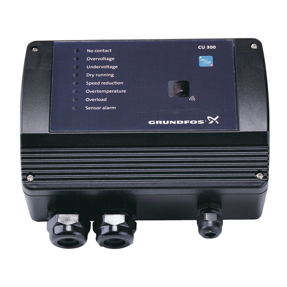
- Page 1 GRUNDFOS INSTRUCTIONS CU 300 Installation and operating instructions No contact Overvoltage Undervoltage Dry running Speed reduction Overtemperature Overload Sensor alarm Other languages www.grundfos.com/CU300-manual...
-
Page 2: Table Of Contents
Mounting CU 300 13.6 Overtemperature CU 300 as an alarm unit 13.7 Overload Description 13.8 Sensor alarm Electrical installation CU 300 with Grundfos GO Description of dry-running protection 14.1 Menu overview Settings Description of functions Description of the dewatering function 15.1 Status CU 300 with constant-pressure control - 15.2 Settings... -
Page 3: Symbols Used In This Document
Red indicator light CU 300 is communicating • too high temperature in motor electronics flashing with the Grundfos GO • supply failure. If you use the On/Off button to stop the pump, As standard, CU 300 incorporates an alarm signal you must also use this button for restarting the relay. -
Page 4: Mechanical Installation
104.5 Fig. 3 CU 300 functions as an alarm unit for the pump. Furthermore, you can communicate with the pump via the remote control Grundfos GO, see also section 14. CU 300 with Grundfos Fig. 2 CU 300 is supplied with a set of gaskets for the Pg screwed connections. -
Page 5: Electrical Installation
4.2 Electrical installation Warning Never make any connections in the CU 300 unit unless the power supply has been switched off. CU 300 must be connected in accordance with the rules and standards in force for the application in question. The supply voltage and frequency are marked on the nameplate. -
Page 6: Description Of Dry-Running Protection
4.4.1 Required Grundfos GO settings You can select the function of the digital input by If the maximum speed of the pump has been means of the Grundfos GO in the display "Digital reduced by more than 1000 min , the dry-running input". -
Page 7: Description Of The Dewatering Function
3. The load decreases, and consequently the pump power input does as well. 4. The pump stops when the power input falls to the dry-running power limit set in the Grundfos GO display 15.2.21 Dry-running stop. The length of the stop time depends on... -
Page 8: Cu 300 With Constant-Pressure Control - 0 To 6 Bar
If you use a diaphragm tank of 8 litres, the pump will The required pressure is set using the start at a flow rate of approx. 0.18 m Grundfos GO. If a you use a larger tank, the flow must Note 5.2 Function... -
Page 9: Positioning The Pressure Sensor
Flow detection 5.3 Positioning the pressure sensor During pump operation, i.e. when water is Pressure loss often causes inconvenience to the consumed, CU 300 will adjust the pump speed to user. CU 300 keeps the pressure constant in the maintain a constant pressure. In order to stop the place where the pressure sensor is positioned. -
Page 10: Electrical Installation
5.5 Electrical installation Warning Never make any connections in the CU 300 unit unless the power supply has been switched off. CU 300 must be connected in accordance with the rules and standards in force for the application in question. The supply voltage and frequency are marked on the nameplate. -
Page 11: Startup
5.5.1 Mains supply 5.5.4 Required Grundfos GO settings You must make the following Grundfos GO settings: POWER, terminals 1, 2 and PE 1. In display "Control mode" select "Closed loop". Connect terminals 1 and 2 to the phase and neutral leads of the mains supply. -
Page 12: Cu 300 With Constant-Pressure Control - 0 To 10 Bar
The required pressure (setpoint) is set in the consumption. The system maintains a constant Grundfos GO display "Setpoint". pressure within the maximum pump performance in • spite of a varying water consumption. -
Page 13: Positioning The Pressure Sensor
6.3 Positioning the pressure sensor Pressure loss often causes inconvenience to the user. CU 300 keeps the pressure constant in the place where the pressure sensor is positioned. See fig. 15. CU 300 Fig. 15 In fig. 15, tap 1 is placed close to the pressure sensor. -
Page 14: Electrical Installation
6.5 Electrical installation Warning Never make any connections in the CU 300 unit unless the power supply has been switched off. CU 300 must be connected in accordance with the rules and standards in force for the application in question. The supply voltage and frequency are marked on the nameplate. -
Page 15: Startup
6.5.1 Mains supply 6.5.4 Required Grundfos GO settings You must make the following Grundfos GO settings: POWER, terminals 1, 2 and PE 1. In display mode" select "Closed 15.2.2 Control Connect terminals 1 and 2 to the phase and neutral loop". -
Page 16: Cu 300 With Constant-Pressure Control - Two-Pump Operation
Set CU 300 (master) to the desired pressure required. The system maintains a constant pressure (setpoint) in the Grundfos GO display "Setpoint". within the maximum pump performance in spite of a •... -
Page 17: Positioning The Pressure Sensor
The pump connected to CU 300 (slave) will be 7.3 Positioning the pressure sensor started in the two following situations: See section 6.3 Positioning the pressure sensor. 1. If the pressure in the diaphragm tank falls to 1 bar below the setpoint. 7.4 System sizing 2. -
Page 18: Electrical Installation
7.5 Electrical installation Warning Never make any connections in the CU 300 unit unless the power supply has been switched off. CU 300 must be connected in accordance with the rules and standards in force for the application in question. The supply voltage and frequency are marked on the nameplate. -
Page 19: Startup
You can connect each terminal to any of the two In this case, 40 less 5 = 35 m. leads. You must make the following Grundfos GO setting on Connect the PE terminal to the green/yellow earth CU 300 (slave): lead. -
Page 20: Cu 300 With Sensors
You can set the alarm, warning and stop limits 8. CU 300 with sensors individually for all sensors connected. The limit settings do not influence each other, and each 8.1 General setting offers its own functioning. CU 300 can be used in systems with one to three Figure 21 shows a schematic presentation of the sensors connected. -
Page 21: Sensor Functioning
1. The pump is stopped. 2. The alarm signal relay operates. 3. The "Sensor alarm" indicator light on CU 300 is 4. The alarm appears in the Grundfos GO display "Alarms and warnings". Max. (stop) Min. (start) If the pump has stopped already or if the alarm signal relay has operated, this condition is maintained. -
Page 22: Electrical Installation
8.3 Electrical installation Warning Never make any connections in the CU 300 unit unless the power supply has been switched off. CU 300 must be connected in accordance with the rules and standards in force for the application in question. The supply voltage and frequency are marked on the nameplate. - Page 23 You must connect each PE terminal to an earth lead of its own. You set the limits for the signal from an external sensor in the Grundfos GO in the "Analog input 1" Maximum cross-section of the leads to be connected and "Analog input 2" displays.
-
Page 24: Cu 300 Connected To Potentiometer
(SPP 1) to "STOP". Figure shows an example of an installation with a potentiometer. Fig. 25 Pos. Description CU 300 External Grundfos potentiometer, SPP 1 The required flow is obtained by changing the motor speed manually using the external potentiometer. Water tank... -
Page 25: Electrical Installation
POWER PUMP ALARM SENSOR SENSOR RS RELAY RELAY 4 3 2 1 SPP 1 Fig. 26 Pos. Description Internal alarm signal relay Relay data: 250 VAC, 1 A, AC1 Alarm signal transmitter (optional) SPP 1 External Grundfos potentiometer, SPP 1... -
Page 26: Cu 300 Connected To Water Meter
9.2.1 Mains supply 9.2.5 Required Grundfos GO settings You must make the following Grundfos GO settings: POWER, terminals 1, 2 and PE 1. In display "Control mode" select "Open loop". Connect terminals 1 and 2 to the phase and neutral leads of the mains supply. -
Page 27: Electrical Installation
10.2 Electrical installation Warning Never make any connections in the CU 300 unit unless the power supply has been switched off. CU 300 must be connected in accordance with the rules and standards in force for the application in question. The supply voltage and frequency are marked on the nameplate. -
Page 28: Constant Water Level
Terminal 13 GND (earth). Level sensor 10.2.5 Required Grundfos GO settings 11.2 Function You must make the following Grundfos GO settings: CU 300 controls the pump speed and consequently 1. Set "Digital input 1". adjusts the pump performance to the borehole yield. -
Page 29: Electrical Installation
11.3 Electrical installation Warning Never make any connections in the CU 300 unit unless the power supply has been switched off. CU 300 must be connected in accordance with the rules and standards in force for the application in question. The supply voltage and frequency are marked on the nameplate. - Page 30 11.3.1 Mains supply 11.3.6 Required Grundfos GO settings You must make the following Grundfos GO settings: POWER, terminals 1, 2 and PE 1. In display "Control mode" select "Closed loop". Connect terminals 1 and 2 to the phase and neutral leads of the mains supply.
-
Page 31: Cu 300 Connected To
CU 300 units only configuration, fault finding and servicing of the • CU 300 units in combination with other Grundfos installation by means of a PC with a PC Tool CU 300 products with GENIbus connection. software. See fig. 31. -
Page 32: Electrical Installation
12.3 Electrical installation Warning Never make any connections in the CU 300 unit unless the power supply has been switched off. CU 300 must be connected in accordance with the rules and standards in force for the application in question. The supply voltage and frequency are marked on the nameplate. - Page 33 Connect terminals 1 and 2 to the phase and neutral The communication is effected according to the leads of the mains supply. You can connect each Grundfos bus protocol, GENIbus, and is two-way terminal to any of the two leads. communication.
-
Page 34: Alarm Functions
The alarm indication "No contact" will also appear if the pump and CU 300 do not have the same number (allocated by the Grundfos GO). The problem may occur e.g. in connection with replacing a motor or a CU 300. -
Page 35: Undervoltage
Borehole filter is Borehole service is blocked. required. Restarting After 5 minutes (factory setting), or the period set by means of the Grundfos GO display "Automatic restarting", the motor will restart automatically. -
Page 36: Speed Reduction
13.5 Speed reduction 13.6 Overtemperature At a moderate undervoltage or overload of the motor, The motor temperature is monitored continuously the speed is reduced, but the motor is not stopped. during operation. The speed reduction indicator light is on, and at the The motor is factory-set to a maximum value. -
Page 37: Overload
See fig. 40. The remote control Grundfos GO is used for wireless infra-red communication with CU 300. During communication, there must be visual contact between CU 300 and the Grundfos GO. See fig. 42. No contact Overvoltage Undervoltage Dry running... -
Page 38: Menu Overview
14.1 Menu overview Status Section Page External setpoint 15.1.1 External setpoint Controlled from 15.1.2 Controlled from Value, sensor 1 15.1.3 Value, sensor 1 and 2 Value, sensor 2 Motor temperature 15.1.4 Motor temperature Motor speed 15.1.5 Motor speed Digital input 15.1.6 Digital input Specific energy 15.1.7 Specific energy... - Page 39 Continued from page 38. Settings Section Page Dry-running protection 15.2.20 Dry-running protection Dry-running stop 15.2.21 Dry-running stop Maximum speed 15.2.22 Maximum speed Buttons on product 15.2.23 Buttons on product Number 15.2.24 Number Store settings 15.2.25 Store settings Recall settings 15.2.26 Recall settings Undo 15.2.27 Undo Unit configuration...
-
Page 40: Description Of Functions
15. Description of functions 15.1.12 Number of starts The value of number of starts is accumulated from the pump's birth and it cannot be reset. 15.1 Status The value is stored in the motor electronics, and it is The "Status" menu for CU 300 offers the possibility kept even if CU 300 is replaced. - Page 41 The following settings are available: The setting in display is overridden 15.2.3 Setpoint • SPP 1. by the "Max." and "Min." settings in display Grundfos potentiometer. 15.2.1 Operating mode. See section 2.1 Expansion possibilities. If you select "Closed loop" in display 15.2.2 Control...
- Page 42 15.2.9 Warning, temperature 15.2.11 Flow per pulse Set the temperature warning limit of the motor. In this display the pumped volume per pulse is set. Setting range: "-" (not active), 2, 4, 6, ..85 °C. Setting range: 0.0, 0.1, 0.2, 0.3, ..20, 21, 22, ..100 l/pulse.
- Page 43 15.2.17 Start delay 15.2.20 Dry-running protection Set a start delay. The following settings are available: This function is used in installations where several • enabled pumps are connected to the same pipeline and • disabled. where it is required that the pumps do not start up at The setting in this display applies to both the the same time.
- Page 44 15.2.23 Buttons on product In this display, you can disable the On/Off button on the control unit for protective reasons. You can set the On/Off button to: • "Active" • "Not active". Factory setting "Active". 15.2.24 Number Allocate a number to CU 300 and the pump connected.
-
Page 45: Alarms And Warnings
15.3 Alarms and warnings 15.3.1 Alarm and warning logs These displays show the types of warnings and alarms that may have appeared. Possible warnings and alarms are described in the following table: Indication Description No fault indication No alarms are registered by CU 300. No contact to pump No communication between CU 300 and the pump. -
Page 46: Technical Data
Current signal: DC 0-20 mA/4-20 mA, R = 500 Ω. Tolerance: ± 3 % at maximum current signal. Screened cable is recommended. Maximum cable length: 500 m. Grundfos fieldbus, GENIbus. 0.25 - 1 mm screened 2-core cable. Maximum cable length: 1200 m. Fig. 43... -
Page 47: Disposal
11 A 12.3 A 12.1 A Sensor alarm "No sensor used" (Grundfos GO setting). See section 15.2.4 Analog inputs) 1) 200-240 V motors: Operation is guaranteed up to 280 VAC. 100-115 V motors: Operation is guaranteed up to 150 VAC. -
Page 48: Declaration Of Conformity
Declaration of conformity GB: EC/EU declaration of conformity We, Grundfos, declare under our sole responsibility that the product CU 300, to which the declaration below relates, is in conformity with the Council Directives listed below on the approximation of the laws of the EC/EU member states. - Page 50 Argentina China Hong Kong Bombas GRUNDFOS de Argentina S.A. GRUNDFOS Pumps (Shanghai) Co. Ltd. GRUNDFOS Pumps (Hong Kong) Ltd. Ruta Panamericana km. 37.500 Centro 10F The Hub, No. 33 Suhong Road Unit 1, Ground floor Industrial Garin Minhang District Siu Wai Industrial Centre 1619 Garín Pcia.
- Page 51 Malaysia Serbia Turkey GRUNDFOS Pumps Sdn. Bhd. Grundfos Srbija d.o.o. GRUNDFOS POMPA San. ve Tic. Ltd. 7 Jalan Peguam U1/25 Omladinskih brigada 90b Sti. Glenmarie Industrial Park 11070 Novi Beograd Gebze Organize Sanayi Bölgesi 40150 Shah Alam Phone: +381 11 2258 740...
- Page 52 96427972 0915 ECM: 1156881 www.grundfos.com...
Need help?
Do you have a question about the cu300 and is the answer not in the manual?
Questions and answers