Chapters
Table of Contents

Related Manuals for ThermoFisher Scientific appliedbiosystems RapidHIT ID System v2.0


Summary of Contents for ThermoFisher Scientific appliedbiosystems RapidHIT ID System v2.0
- Page 1 RapidHIT ID System v2.0 ™ USER GUIDE for use with: RapidLINK Software v2.0 ™ Publication Number MAN0026593 Revision B00 For Forensic, Human Identification, or Paternity/Kinship Use Only. Not for use in diagnostic procedures.
- Page 2 Life Technologies Corporation | 200 Oyster Point Blvd | South San Francisco, California 94080 USA For descriptions of symbols on product labels or product documents, go to thermofisher.com/symbols-definition. Revision history: MAN0026593 B00 (English) Revision Date Description 18 March 2024 Added reference to subsampling procedures (“Subsampling” page 17).
- Page 3 Contents ■ CHAPTER 1 Product information ..........7 Product description .
- Page 4 Contents Start the run ..............30 Run times for different sample cartridges .
- Page 5 Contents ■ APPENDIX A Troubleshooting ........... 83 Check the RapidLINK Software connection ...
- Page 6 Contents ■ APPENDIX E Touchscreen descriptions ........145 Insert cartridge screen .
-
Page 7: Product Information
Product information ■ Product description ..............7 ■... - Page 8 Chapter 1 Product information Sample cartridge types Sample cartridge types Sample cartridge Sample type STR chemistry Features • Systematic allelic ladder library RapidHIT ID ACE Single-source, buccal GlobalFiler ™ ™ GlobalFiler Express swab Express • Optimized data analysis thresholds ™ Sample Cartridge For more information, see Appendix C, “RapidHIT ID System v2.0 validation...
- Page 9 Chapter 1 Product information Sample cartridge types Sample cartridge components The sample cartridges include the following components. Sample swab chamber Crosshatch cuts in the cartridge film (× 10) Cartridge label RFID tag Waste sponge Pre-mix (clear) Size standard Primer mix (pink) DNA capturing paper Note: The insertion flag is not visible in this view.
-
Page 10: Parts Of The Instrument
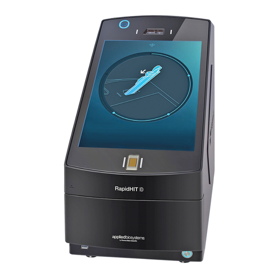
Chapter 1 Product information Parts of the instrument Parts of the instrument Camera Power button (controls the internal computer) Sample cartridge port USB port Touchscreen (display screen) Rear panel with main power switch, USB, and computer connections Fingerprint reader Primary cartridge (contains gel cartridge) The instrument also includes an internal environmental sensor that monitors temperature and humidity. -
Page 11: Required Materials Not Supplied
Chapter 1 Product information Required materials not supplied Required materials not supplied Unless otherwise indicated, all materials are available through thermofisher.com. "MLS" indicates that the material is available from fisherscientific.com or another major laboratory supplier. Catalog numbers that appear as links open the web pages for those products. Primary cartridge kit Note: For the primary cartridge kit, the allelic ladder, negative control, positive control, and utility cartridges can be ordered separately through your local Thermo Fisher Scientific sales representative. - Page 12 Chapter 1 Product information Required materials not supplied Sample cartridge kits Table 2 RapidINTEL Plus sample cartridge kits ™ Cat. No. Contents Amount Storage RapidINTEL Plus 50 Sample A54338 RapidINTEL Plus Sample ™ ™ Cartridge Kit Cartridge RapidINTEL Plus Negative ™ 15–25℃ for Control Cartridge ≤2 months, or 4–10℃...
- Page 13 Chapter 1 Product information Network and password security requirements Table 5 GlobalFiler Express allelic ladder, control, and utility cartridges ™ Contents Cat. No. Amount Storage RapidHIT ID ACE GlobalFiler Express 400096RH 4–10°C ™ ™ Control (Ladder) 5-Cartridge Kit RapidHIT ID ACE GlobalFiler Express A42470 ™...
-
Page 14: Password Security
Chapter 1 Product information User role permissions Password security Thermo Fisher Scientific strongly recommends that you maintain unique passwords for all accounts in use on this product. All passwords should be reset upon first sign in to the product. Change passwords according to your organization's password policy. It is the sole responsibility of your IT personnel to develop and enforce secure use of passwords. - Page 15 Chapter 1 Product information Workflow Workflow Obtain a swab or substrate sample according to your standard operating procedure. Insert the swab or substrate sample into a sample cartridge. Sign in to the instrument. Insert the sample cartridge into the instrument. Enter the sample identification number or scan the sample cartridge barcode.
- Page 16 Chapter 1 Product information Workflow (RapidINTEL Plus sample ™ cartridges only) Select a sample protocol Depending on the workflow for your instrument, you may be prompted to select a sample protocol. Start the run Review the information on the screen, then start the run.
-
Page 17: Sample Collection
Collect and prepare the sample Sample collection Sample cartridges were validated using the following swab types, but other swab types have been used successfully with both cartridges. • GlobalFiler Express—Puritan 3″ Sterile Standard Cotton Swab with Semi-Flexible Polystyrene ™ ™ Handle •... -
Page 18: Table Of Contents
Run the instrument ■ Power on the internal computer ............19 ■... -
Page 19: Power On The Internal Computer
Chapter 3 Run the instrument Power on the internal computer Power on the internal computer Note: If you are starting the RapidHIT ID System v2.0 instrument for the first time, see “Configure the ™ server connection (at initial startup)” page 36. If you are starting the instrument after it has been running in standalone mode, see “Configure the server connection (after running in standalone mode)”... -
Page 20: Sign In To The Instrument
Chapter 3 Run the instrument Sign in to the instrument Sign in to the instrument By default, two-factor authentication (2FA) is enabled. When 2FA is enabled, a password/PIN and one biometric (fingerprint scan or face recognition) are required to sign in. When 2FA is disabled, only one factor is required to sign in. If your user account is configured with multiple sign-in factors, you can use any one of the factors to sign in. - Page 21 Chapter 3 Run the instrument Sign in to the instrument Dropdown list to select your user name User name field to search for your user name Alphanumeric keypad to search for your user name Dropdown list or search results 3. At the bottom of the screen, tap to display a numeric keypad, then enter your password/PIN.
- Page 22 Chapter 3 Run the instrument Sign in to the instrument 4. (If needed) When two factor authentication (2FA) is enabled, a password/PIN and one biometric (fingerprint scan or face recognition) are required to sign in to the instrument. Use the appropriate factor to complete the sign-in process. •...
- Page 23 Chapter 3 Run the instrument Sign in to the instrument Sign in to the instrument—Fingerprint scan 1. (If needed) When two factor authentication (2FA) is enabled, you must enter a password/PIN before scanning your fingerprint. See “Sign in to the instrument—Password/PIN” page 20. 2.
- Page 24 Chapter 3 Run the instrument Sign in to the instrument 3. At the bottom of the screen, tap , then position your face in front of the camera. Proceed to “After signing in—next steps” page 24. After signing in—next steps 1. After you sign in, the insert cartridge screen is displayed. For a detailed description of this screen, see “Insert cartridge screen”...
-
Page 25: Insert The Sample Cartridge Into The Instrument
Chapter 3 Run the instrument Insert the sample cartridge into the instrument Insert the sample cartridge into the instrument When the insert cartridge screen is displayed, insert the sample cartridge (containing the sample swab) into the sample cartridge port. See the following figures. The enter sample ID number screen is displayed. - Page 26 Chapter 3 Run the instrument Enter the sample identification number Manually enter a sample ID or barcode 1. In the enter sample ID number screen, use the alphanumeric keypad to enter the sample ID or barcode. By default, the enter sample ID number screen displays the alphanumeric keypad. If the screen displays the camera for scanning a barcode, tap the in the center of the screen to display the keypad.
-
Page 27: Select A Sample Category
Chapter 3 Run the instrument Select a sample category The enter sample ID number screen, with the camera displayed. To manually enter a sample ID or barcode, tap , then see “Manually enter a sample ID or barcode” page 26. 2. Hold the barcode in front of the camera at the top left of the instrument. After the camera reads the barcode, the Sample category prompt is displayed. -
Page 28: (Rapidintel ™ Plus Sample Cartridge Only) Select A Sample Protocol
Chapter 3 Run the instrument (RapidINTEL Plus sample cartridge only) Select a sample protocol ™ Dropdown list to select a sample category User name field to search for a sample category Alphanumeric keypad to search a sample category Dropdown list or search results Proceed to one of the following, depending on your workflow: •... - Page 29 Chapter 3 Run the instrument (RapidINTEL Plus sample cartridge only) Select a sample protocol ™ Note: Workflows are configured in the RapidLINK Software. For more information, see the ™ RapidLINK Software v2.0 User Guide (Pub. No. MAN0030010). ™ At the Select sample protocol prompt, tap the appropriate sample protocol. •...
-
Page 30: Start The Run
Chapter 3 Run the instrument Start the run Start the run 1. Review the information on the screen. 2. If any of the information needs to be corrected, tap You will be prompted to remove the cartridge, re-insert it, then re-enter all of the run information. 3. -
Page 31: View The Run Results And Remove The Sample Cartridge
Chapter 3 Run the instrument View the run results and remove the sample cartridge View the run results and remove the sample cartridge 1. When the run is complete, the lock screen is displayed. Tap the lock screen, then sign in (see “Sign in to the instrument”... - Page 32 Chapter 3 Run the instrument View the run results and remove the sample cartridge 4. When the remove cartridge screen is displayed, remove the cartridge from the instrument. IMPORTANT! Remove the cartridge only when the remove cartridge screen is displayed. If the lock screen is displayed before you have a chance to remove the cartridge: Sign in again, wait for the remove cartridge screen, then remove the cartridge.
-
Page 33: Sign Out
Chapter 3 Run the instrument Sign out Sign out The signed-in user is automatically signed out in the following instances: • When a run is completed • If there is no user activity on the touchscreen for ≥2 minutes You can manually sign out whenever the lock icon ( ) is displayed. - Page 34 Manage the instrument and software ■ View run log ............... . . 35 ■...
-
Page 35: View Run Log
Chapter 4 Manage the instrument and software View run log View run log The run log displays a history of all runs performed on the instrument, including the upload and export status of the run. If your user role includes the View all runs permission, you can view a run log for all runs performed by all users. -
Page 36: Configure Instrument Settings
Chapter 4 Manage the instrument and software Configure instrument settings Configure instrument settings Connect or disconnect (server) Configure the server connection (at initial startup) Note: To connect an instrument that has been running in standalone mode, see “Configure the server connection (after running in standalone mode)” page 42. - Page 37 Chapter 4 Manage the instrument and software Configure instrument settings Figure 4 IP address or host name Port Tap to connect to the specified server Connection is successful Note: If you receive an error message, see “"Failed to connect to server" error message is displayed”...
- Page 38 Chapter 4 Manage the instrument and software Configure instrument settings Note: If you disconnect the instrument from a RapidLINK server when the instrument is offline, ™ the RapidLINK Software will not register the disconnection. A RapidLINK Software user must ™ ™ manually disconnect the instrument from within the RapidLINK Software.
- Page 39 Chapter 4 Manage the instrument and software Configure instrument settings 3. If there are runs queued for upload to the RapidLINK server, the prompt Disconnecting will stop ™ the data upload appears. We recommend that you export the queued runs before continuing. a.
- Page 40 Chapter 4 Manage the instrument and software Configure instrument settings 5. At restart, you are prompted to select a server connection. Tap the appropriate connection option. • RapidLINK server—Tap YES to connect the instrument to a RapidLINK server, then ™ ™ proceed to .step 6. •...
- Page 41 Chapter 4 Manage the instrument and software Configure instrument settings 8. Sign in as the first administrator, then create new user accounts as needed. Connection status Accounts Connecting to a • If the RapidLINK server includes any instrument user accounts that ™ RapidLINK server are authorized for this instrument, those accounts are automatically...
- Page 42 Chapter 4 Manage the instrument and software Configure instrument settings Configure the server connection (after running in standalone mode) Note: If you are starting the instrument for the first time, see “Configure the server connection (at initial startup)” page 36. Perform this procedure to connect to a RapidLINK server after the instrument has been running in ™...
- Page 43 Chapter 4 Manage the instrument and software Configure instrument settings 3. At the All users will be removed from the instrument prompt, tap YES to continue. All user accounts that were created while the instrument was in standalone mode will be removed. Note: If you do not want the user accounts to be removed, tap NO to discontinue.
-
Page 44: Export Data
Chapter 4 Manage the instrument and software Configure instrument settings Figure 6 IP address or host name Port Tap to connect to the specified server Connection is successful Note: If you receive an error message, see “"Failed to connect to server" error message is displayed”... - Page 45 Chapter 4 Manage the instrument and software Configure instrument settings 3. If multiple devices are inserted in the instrument, tap the left or right arrow to select the appropriate drive. Note: If only one device is inserted, the correct drive is automatically selected. 4.
- Page 46 Chapter 4 Manage the instrument and software Configure instrument settings 5. Select the checkboxes for the data to export. Item Description .fsa Exports all sample files (FSA). Exports all project files (SER). .ser Exports all FSA files, SER files, and run folders. Runs Selecting the Runs checkbox, automatically selects the .fsa and .ser checkboxes.
- Page 47 Chapter 4 Manage the instrument and software Configure instrument settings Note: For the .fsa, .ser, and Runs options: If the RapidHIT ID Instrument is configured to ™ automatically delete run data after the data are transferred to the RapidLINK Software, there ™ may not be any data available to export.
- Page 48 Chapter 4 Manage the instrument and software Configure instrument settings 4. At the prompt, create a demo administrator account and (optional) any other demo user accounts. For information on creating user accounts, see “Add a user account (new user)” page 59. Note: New demo user accounts must be created each time that you enable demo mode. All demo user accounts are removed when you disable demo mode.
- Page 49 Chapter 4 Manage the instrument and software Configure instrument settings (continued) Action Perform a simulated run with cartridges Follow the prompts to perform the simulated run. For detailed information on performing a run, see Chapter 3, “Run the instrument”. Note the following: • When prompted to insert a cartridge, ensure that you use the appropriate cartridge. •...
- Page 50 Chapter 4 Manage the instrument and software Configure instrument settings Yellow Demo mode banner is displayed on the touchscreen Demo mode toggle button—demo mode enabled Opens a settings menu for simulated runs Demo runs are uploaded to the RapidLINK Software, where users can view the demo runs for training ™...
- Page 51 Chapter 4 Manage the instrument and software Configure instrument settings Common Callouts and Arrows 1. Copy-paste a callout or arrow to use in this SVG. Disable demo mode Note: If you need more advanced callouts or arrows use the TechComm_Inkscape_Callout&Arrow_Libary. 2. Edit number and/or line-length, as needed. 1.
- Page 52 Chapter 4 Manage the instrument and software Configure instrument settings Demo mode toggle button—demo mode disabled Adjust the instrument time zone 1. Tap , then tap 2. At the bottom of the screen, tap the left or right arrow to adjust the time zone of the instrument. The current date and time of the selected time zone is displayed.
- Page 53 Chapter 4 Manage the instrument and software Configure instrument settings Time zone Current date and time RapidHIT ID System v2.0 User Guide ™...
-
Page 54: Configure Instrument Options
Chapter 4 Manage the instrument and software Configure instrument options Configure instrument options 1. Tap , then tap 2. Configure the instrument options as needed. RapidHIT ID System v2.0 User Guide ™... -
Page 55: Manage Workflows
Chapter 4 Manage the instrument and software Manage workflows Common Callouts and Arrows Setting Description Default 1. Copy-paste a callout or arrow to use in this SVG. Note: If you need more advanced callouts or arrows use the TechComm_Inkscape_Callout&Arrow_Libary. Two factor When enabled, requires a password/PIN and one biometric (fingerprint scan or Enabled 2. - Page 56 Chapter 4 Manage the instrument and software Manage workflows Methods for assigning an instrument to a workflow There are three methods for assigning an instrument to a workflow: • Default assignment—Each RapidHIT ID instrument is shipped with the default system-defined ™ workflow. •...
- Page 57 Chapter 4 Manage the instrument and software Manage workflows The following occurs: • A progress message is displayed. • When the install is complete, the instrument software automatically restarts (the restart takes ~1– 2 minutes). • The workflow change is applied to all existing and new user accounts the next time that each user signs in.
-
Page 58: Manage Users
Manage users ■ Search for a user account ............. 58 ■... -
Page 59: Add A User Account (New User)
Chapter 5 Manage users Add a user account (new user) Search for a user field Alphanumeric keypad Search results; scroll down if needed Clear search results Add a user account (new user) When a user account is created on one RapidHIT ID instrument, that same user account can be ™... - Page 60 Chapter 5 Manage users Add a user account (new user) 3. Enter a user name with the alphanumeric keypad, then tap ENTER. Enter a user name with the alphanumeric keypad Tap ENTER 4. Use the left or right arrow to select a user role Supervisor, Administrator, or Operator. Arrows to select a user role IMPORTANT! Do not select the Existing user checkbox for new RapidHIT ID instrument users.
- Page 61 Chapter 5 Manage users Add a user account (new user) User authentication methods Option Action Password/PIN a. Tap b. Enter a PIN (6 characters) two times with the numeric keypad, then tap A success message is displayed. The message closes automatically after a few seconds.
- Page 62 Chapter 5 Manage users Add a user account (new user) Email ID and SMS options Option Action Email ID a. Tap b. Tap the Enter Email ID field. c. Enter an email address with the alphanumeric keypad, then tap ENTER. d. Tap A success message is displayed.
-
Page 63: Add A User Account (Existing User)
Chapter 5 Manage users Add a user account (existing user) Save A success message is displayed. The message closes automatically after a few seconds. Add a user account (existing user) This procedure is available only when both of the following circumstances are met: •... - Page 64 Chapter 5 Manage users Add a user account (existing user) Enter a user name with the alphanumeric keypad Tap ENTER 4. Select the Existing user checkbox. Existing user checkbox RapidHIT ID System v2.0 User Guide ™...
-
Page 65: Edit A User Account (Includes Password/Pin Reset)
Chapter 5 Manage users Edit a user account (includes password/PIN reset) 5. At the prompt, tap YES to confirm. 6. Complete the remaining user account information. For detailed instructions, see “Add a user account (new user)” page 59. When the new instrument comes back online, the RapidLINK Software recognizes the user account ™... - Page 66 Chapter 5 Manage users Edit a user account (includes password/PIN reset) 3. (Duplicate user names only) If a user account is flagged with , it indicates that it is a duplicate user account. To resolve the duplication, edit the user name or accept the temporary user name provided.
- Page 67 Chapter 5 Manage users Edit a user account (includes password/PIN reset) User authentication methods RapidHIT ID System v2.0 User Guide ™...
- Page 68 Chapter 5 Manage users Edit a user account (includes password/PIN reset) Option Action Password/PIN For users who know their PIN: 1. Tap 2. Enter the user's current PIN (6 characters) with the numeric keypad. 3. Enter a new PIN (6 characters) two times with the numeric keypad, then tap A success message is displayed.
- Page 69 Chapter 5 Manage users Edit a user account (includes password/PIN reset) Email ID and SMS options Option Action Email ID a. Tap b. Tap the Enter Email ID field. c. Enter an email address with the alphanumeric keypad, then tap ENTER. d. Tap A success message is displayed.
-
Page 70: Edit A User Role
Chapter 5 Manage users Edit a user role Save A success message is displayed. The message closes automatically after a few seconds. Edit a user role There are three default user roles in the instrument software: administrator, supervisor, and operator. • You cannot delete the default user roles or create new user roles. •... -
Page 71: Software
Chapter 5 Manage users Manually download user accounts from the RapidLINK Software ™ 3. Edit the permissions for the supervisor or operator role: Select and deselect the checkboxes as needed. The default permissions for each user role are displayed below. 4. (If needed) Tap Restore to default to restore the default permissions for the supervisor and operator roles. -
Page 72: Software)
Chapter 5 Manage users Authorize or deauthorize a user account (RapidLINK Software) ™ Authorize or deauthorize a user account (RapidLINK ™ Software) In the instrument software, users are automatically authorized for the instrument that their user account was created on. Otherwise, authorization and deauthorization must be applied from the RapidLINK ™... -
Page 73: Maintain The Instrument
Maintain the instrument ■ Routine maintenance ..............73 ■... - Page 74 Chapter 6 Maintain the instrument Routine maintenance Maintenance (new utility cartridge required) Action Frequency When maintenance is required, the instrument automatically displays the insert utility cartridge Every screen. 15 days Note: Utility cartridges can be ordered separately through your local Thermo Fisher Scientific sales representative.
-
Page 75: View Primary Cartridge Information
Chapter 6 Maintain the instrument View primary cartridge information View primary cartridge information If the sample identification screen is not displayed, tap until it is displayed. The screen displays the following information for the primary cartridge: Expiration date, number of runs performed, and gel volume indicator. -
Page 76: Replace The Primary Cartridge
Chapter 6 Maintain the instrument Replace the primary cartridge Replace the primary cartridge To replace the primary cartridge, your user role must include the Replace primary cartridge permission. For more information on user role permissions, see “Edit a user role” page 70. This procedure requires ~2 hours to complete. Parts of the primary cartridge The following figures illustrate the parts of the primary cartridge. - Page 77 Chapter 6 Maintain the instrument Replace the primary cartridge Note: For RapidINTEL Plus applications, use a primary cartridge from the RapidHIT ID Primary ™ ™ Cartridge GlobalFiler Express 150 Kit. ™ Prepare the primary cartridge according to the instructions provided with the cartridge. For the location of the primary cartridge parts, see Figure 7 page 76.
- Page 78 Chapter 6 Maintain the instrument Replace the primary cartridge 2. Tap Yes to confirm that you want to remove the primary cartridge. 3. When the insert utility cartridge screen is displayed, insert the utility cartridge into the instrument. The utility cartridge has a red label and is provided with the new primary cartridge. A countdown timer starts at 10 minutes while the instrument disengages the primary cartridge.
- Page 79 Chapter 6 Maintain the instrument Replace the primary cartridge 5. When the insert primary cartridge screen is displayed, insert the prepared primary cartridge into the instrument. CAUTION! The capillary is fragile. Do not let the capillary contact the instrument when you insert the prepared primary cartridge. A countdown timer is displayed.
- Page 80 Chapter 6 Maintain the instrument Replace the primary cartridge Run a positive control cartridge The following component is required for this procedure: • Positive control cartridge that is provided with the new primary cartridge For each sample cartridge type that will be used, a positive control cartridge must be run immediately after a new primary cartridge is inserted.
- Page 81 Chapter 6 Maintain the instrument Replace the primary cartridge (Recommended) Run an allelic ladder cartridge The following component is required for this procedure: • Allelic ladder cartridge that is provided with the new primary cartridge Note: Allelic ladder cartridges can also be ordered separately through your local Thermo Fisher Scientific sales representative.
-
Page 82: Control Cartridge Results
Chapter 6 Maintain the instrument Control cartridge results Control cartridge results Table 7 Results for allelic ladder, negative control, and/or positive control cartridges DNA profile Status Description Action generated • The DNA profile does not contain quality flags. Green No further action is needed on the •... -
Page 83: Troubleshooting
Troubleshooting ■ ™ Check the RapidLINK Software connection ..........83 ■... - Page 84 Appendix A Troubleshooting Troubleshooting: Observations, causes, and actions Observation Possible cause Recommended action The cartridge is improperly Remove the cartridge from is displayed on the remove cartridge screen inserted in the instrument. the instrument and re-insert. The cartridge is not Remove the cartridge from supported by the instrument.
- Page 85 Appendix A Troubleshooting Troubleshooting: Observations, causes, and actions Observation Possible cause Recommended action A positive control cartridge Run a positive control is displayed on the touchscreen must be run on the cartridge. See “Run a instrument. positive control cartridge” page 80. For each sample cartridge type that will be used, a positive control cartridge must be run immediately after...
- Page 86 Appendix A Troubleshooting Troubleshooting: Observations, causes, and actions Observation Possible cause Recommended action The instrument camera is Enable the camera. is displayed on the touchscreen disabled. See “Configure instrument options” page 54. Note: You will also see a "Camera is turned OFF" message when you attempt a scan.
- Page 87 Appendix A Troubleshooting Troubleshooting: Observations, causes, and actions Observation Possible cause Recommended action "Failed to connect to server" error message is The message may be caused Perform any of the following, displayed by various communication as needed: issues. • Check the network connection.
- Page 88 Appendix A Troubleshooting Troubleshooting: Observations, causes, and actions Observation Possible cause Recommended action A power failure occurs during a run Various causes. If the power failure occurs early in the run, the run will stop and it will not be listed in the run log. Obtain a new swab and rerun the sample.
- Page 89 DX codes Restart DX code Error description Action required The ambient temperature is not within Ensure that the ambient temperature is 15–30℃ (59–86℉). specification for running the instrument. The sample injection was not detected. Contact Thermo Fisher Scientific Technical Support. The sample injection was delayed.
- Page 90 (continued) Restart DX code Error description Action required The heater is not reaching the required Press the front button to power off the instrument, then press temperature in the allotted time frame. the rear button to restart the instrument. A new primary or mezzanine board may be required.
- Page 91 (continued) Restart DX code Error description Action required In the primary cartridge, the gel reprime was Restart the instrument, then re-insert the primary cartridge. A lower than expected. new utility cartridge will be required. In the sample cartridge, the gel reprime was lower Restart the instrument, then insert a new sample cartridge.
- Page 92 Appendix A Troubleshooting Perform the SCCL recovery procedure Perform the SCCL recovery procedure If an SCCL error occurs during a run, the lock the screen is displayed with a yellow triangle. 1. Tap the lock screen, then sign in (see “Sign in to the instrument” page 20).
- Page 93 Appendix A Troubleshooting Perform the SCCL recovery procedure 4. When the insert utility cartridge screen is displayed, insert a new utility cartridge into the instrument. The instrument prepares for the recovery steps, then displays the countdown timer. The recovery can take ~5–10 minutes. RapidHIT ID System v2.0 User Guide ™...
- Page 94 Appendix A Troubleshooting Perform the SCCL recovery procedure 5. When the remove utility cartridge screen is displayed, remove the utility cartridge from the instrument. 6. If the lock screen is displayed, tap the screen, then sign in. 7. When the insert cartridge screen is displayed, insert a new sample cartridge into the instrument to perform a new run.
-
Page 95: Analysis Settings
Analysis settings ■ General analysis settings ............. . 95 ■... - Page 96 Appendix B Analysis settings General analysis settings (continued) RapidHIT ID ACE GlobalFiler ™ ™ Analysis parameter RapidINTEL Plus cartridges ™ Express cartridges Range filter (From/To) 92.0/102.2 (Green) 76.0/91.0 (Blue) 89.7/98.0 (Green) Use marker-specific True True thresholds Analysis range Full range Full range Sizing range All sizes All sizes...
- Page 97 Appendix B Analysis settings General analysis settings (continued) RapidHIT ID ACE GlobalFiler ™ ™ Analysis parameter RapidINTEL Plus cartridges ™ Express cartridges SQ & GQ settings All default All default Size standard definition RapidHITID_SS3_Size_Standard RapidHITID_GS600_Size_Standard name RapidHIT ID System v2.0 User Guide ™...
- Page 98 Appendix B Analysis settings Marker-specific settings for RapidHIT ID ACE GlobalFiler Express cartridges ™ ™ Marker-specific settings for RapidHIT ID ACE GlobalFiler ™ ™ Express cartridges Peak Amplitude Hm. Minimum Hz. Minimum Minimum Peak Maximum Peak Locus Cut-off Threshold Peak Height Peak Height Height Ratio Height D3S1358...
- Page 99 Appendix B Analysis settings Marker-specific settings for RapidINTEL Plus cartridges ™ Marker-specific settings for RapidINTEL Plus cartridges ™ Peak Amplitude Hm. Minimum Hz. Minimum Minimum Peak Maximum Peak Locus Cut-off Threshold Peak Height Peak Height Height Ratio Height 35 RFU 35 RFU D3S1358 180 RFU 287 RFU 0.13 D16S539...
- Page 100 Appendix B Analysis settings Stutter thresholds for RapidHIT ID ACE GlobalFiler Express cartridges ™ ™ Stutter thresholds for RapidHIT ID ACE GlobalFiler ™ ™ Express cartridges Note: When not indicated, the stutter threshold is –3.25 to –4.75 nucleotides from the allele peak. Locus Stutter threshold D3S1358...
- Page 101 Appendix B Analysis settings Stutter thresholds for RapidINTEL Plus cartridges ™ Stutter thresholds for RapidINTEL Plus cartridges ™ Note: When not indicated, the stutter threshold is ±3.25–4.75 nucleotides from the allele peak. Locus Minus stutter threshold Plus stutter threshold 0.90 (–0.25 to –4.8 nucleotides) 0.90 (0.25–4.0 nucleotides) 0.22 0.03...
- Page 102 Appendix B Analysis settings Artifact thresholds and filters for RapidINTEL Plus cartridges ™ (continued) Locus Minus stutter threshold Plus stutter threshold 0.27 0.03 D12S391 0.26 0.03 D2S1338 Artifact thresholds and filters for RapidINTEL Plus ™ cartridges The RapidINTEL Plus assay requires filters for potential amplification artifacts that may be caused by ™...
-
Page 103: Objective Of The Validation
RapidHIT ID System v2.0 validation ™ studies ■ Objective of the validation ............103 ■... -
Page 104: Analysis Thresholds
Appendix C RapidHIT ID System v2.0 validation studies ™ Analysis thresholds • Mixture • Reliability Analysis thresholds Before completing the validation studies, a calibration data set was used to establish various analysis thresholds for RapidHIT ID System v2.0. 961 data files that were generated from ACE GFE sample ™... - Page 105 Appendix C RapidHIT ID System v2.0 validation studies ™ Analysis thresholds Peak height ratio (PHR) PHR data from the population data set was calculated and plotted for all non-haploid loci. The PHR distribution was analyzed to find the 0.1% quantile and used to establish an acceptable PHR limit for system flagging.
- Page 106 Appendix C RapidHIT ID System v2.0 validation studies ™ Analysis thresholds Threshold results The thresholds established from the calibration data set for allele calling and quality flagging are summarized in Table 9. These values were implemented for the validation studies. Details for setting the AT, ST, PHR, and stutter filter values are provided below Table 9. Table 9 Analysis setting thresholds Threshold type Threshold setting in the software...
- Page 107 Appendix C RapidHIT ID System v2.0 validation studies ™ Analysis thresholds Stochastic threshold (ST) The ST per locus is provided in Table 9. The minimum peak height ratios used to calculate ST are listed in the Minimum PHR column. The ST column represents the ST using an analytical threshold (AT) of 35 RFU.
- Page 108 Appendix C RapidHIT ID System v2.0 validation studies ™ Analysis thresholds Peak height ratio (PHR) Distribution of the peak height ratios is shown in Figure 10. An evaluation determined that a 35% PHR balanced genotype accuracy and increased system pass rate by reducing false flagging of true heterozygote pairs.
- Page 109 Appendix C RapidHIT ID System v2.0 validation studies ™ Analysis thresholds Stutter ratio Marker Stutter filter Minimum Maximum Average Standard deviation D3S1358 6.0% 14.4% 9.9% 1.7% 2.7% 14.7% 7.9% 2.5% D16S539 2.6% 13.5% 7.1% 2.0% CSF1PO 2.9% 14.4% 7.7% 1.6% TPOX 1.8% 6.0% 3.6% 1.0%...
-
Page 110: Materials Used In The Validation
Appendix C RapidHIT ID System v2.0 validation studies ™ Materials used in the validation Materials used in the validation Instruments 12 RapidHIT ID System v2.0 instruments were used for validation studies. All instruments were not ™ used in every study; however, each instrument was used in at least one study. Software Software Version number... -
Page 111: Population Study
Appendix C RapidHIT ID System v2.0 validation studies ™ Population study (continued) Study Sample Details 130 ACE GFE sample cartridges: Sensitivity 5 replicates of each input • 40 buccal swipes (male donor)—1, 5, 10, and 20 amount on 2 RapidHIT ID ™ instruments •... - Page 112 Appendix C RapidHIT ID System v2.0 validation studies ™ Population study Run and analysis summary 11 RapidHIT ID instruments ran a total of 500 samples that gave a profile: ™ • 440 runs passed with no quality flags ( ). This represented a first pass success rate of 86.3% (440/510).
- Page 113 Appendix C RapidHIT ID System v2.0 validation studies ™ Population study Table 12 Population study: Reasons for the quality flags—for the 44 runs that passed with review (continued) Reason for quality flag ( Number of samples Stutter at D19S433 TH01 –5 nt artifact DYS391 to SE33 pull-up D19S433 –3 nt artifact (unflagged) Y indel artifact D2S441 MinusA...
- Page 114 Appendix C RapidHIT ID System v2.0 validation studies ™ Population study Figure 11 6‑FAM dye: Stutter percent vs. marker and parent allele ™ The horizontal gray lines represent the stutter filter for each locus. See “Stutter” on page 108 and “Stutter thresholds for RapidHIT ID ACE GlobalFiler Express cartridges”...
- Page 115 Appendix C RapidHIT ID System v2.0 validation studies ™ Population study Figure 12 NED dye: Stutter percent vs. marker and parent allele ™ The horizontal gray lines represent the stutter filter for each locus. See “Stutter” on page 108 and “Stutter thresholds for RapidHIT ID ACE GlobalFiler Express cartridges”...
- Page 116 Appendix C RapidHIT ID System v2.0 validation studies ™ Population study Figure 14 TAZ dye: Stutter percent vs. marker and parent allele ™ The horizontal gray lines represent the stutter filter for each locus. See “Stutter” on page 108 and “Stutter thresholds for RapidHIT ID ACE GlobalFiler Express cartridges”...
- Page 117 Appendix C RapidHIT ID System v2.0 validation studies ™ Population study Pull-up When the locus-specific filter and global cut-off settings were applied, all pull-up peaks were filtered out in 484 of the 500 profiles tested. 16 of the 500 profiles (3.2%) triggered quality flags because of pull-up: •...
- Page 118 Appendix C RapidHIT ID System v2.0 validation studies ™ Population study Sizing accuracy Sizing accuracy is defined as the difference in base pairs (bp) between the observed allele size and the Common Callouts and Arrows mean allele size for all observations of that allele. 1.
-
Page 119: Precision Study
Common Callouts and Arrows Appendix C RapidHIT ID System v2.0 validation studies ™ 1. Copy-paste a callout or arrow to use in this SVG. Precision study Note: If you need more advanced callouts or arrows use the TechComm_Inkscape_Callout&Arrow_Libary. Precision study 2. Edit number and/or line-length, as needed. Precision was measured by calculating and plotting the standard deviation of the size values for each 3. -
Page 120: Reproducibility And Repeatability (R&R) Study
Appendix C RapidHIT ID System v2.0 validation studies ™ Reproducibility and repeatability (R&R) study Figure 19 Precision study: Size standard deviation vs. mean size within instruments 5 GFE allelic ladder cartridges per instrument Reproducibility and repeatability (R&R) study Reproducibility and repeatability indicates that the same result is achieved with repeated processing of the same sample. - Page 121 Appendix C RapidHIT ID System v2.0 validation studies ™ Reproducibility and repeatability (R&R) study Peak heights by marker Figure 20 R&R study: Peak heights by marker 30 ACE GFE positive control cartridges. Peak height ratio (PHR) by marker Figure 21 R&R study: PHR by marker 30 ACE GFE positive control cartridges. RapidHIT ID System v2.0 User Guide ™...
-
Page 122: Sensitivity Study
Appendix C RapidHIT ID System v2.0 validation studies ™ Sensitivity study Sensitivity study Comm 1. Copy-p Cartridge and sample summary Note: 3 sensitivity series were run with ACE GFE sample cartridges: use th • Buccal swipe series—40 cartridges • gDNA series—50 cartridges 2. - Page 123 Appendix C RapidHIT ID System v2.0 validation studies ™ Sensitivity study Figure 23 Sensitivity study: gDNA series DNA Control 007; 10 replicates per concentration Run and analysis summary: Saliva series 2 RapidHIT ID instruments ran 5 replicates of each dilution amount. ™ • Input amounts were a decreasing series of saliva dilutions: starting with neat saliva, then 1:5, 1:10, and 1:20 diluted saliva, for 4 input amounts in total.
-
Page 124: Carryover Study
Appendix C RapidHIT ID System v2.0 validation studies ™ Carryover study Figure 24 Sensitivity study: Saliva series Male donor; 10 replicates per dilution Carryover study Carryover studies indicate whether there is sample carryover from one run to the next. Cartridge and sample summary 2 cartridge types were used: •... - Page 125 Appendix C RapidHIT ID System v2.0 validation studies ™ Carryover study RapidHIT ID instrument ™ ACE GFE cartridge Sample (2,400 ng of DNA Control 007) — — Negative control Sample (2,400 ng of DNA Control 007) — — Negative control Sample (2,400 ng of DNA Control 007) —...
- Page 126 Appendix C RapidHIT ID System v2.0 validation studies ™ Carryover study Figure 26 Carryover study: Negative controls overlaid—VIC ™ 10 alternating runs. The red arrows indicate bins for the DNA Control 007 genotype. The gray line is the analytical threshold. Y-axis: RFU 0–36. Figure 27 Carryover study: Negative controls overlaid—NED ™...
- Page 127 Appendix C RapidHIT ID System v2.0 validation studies ™ Carryover study Figure 28 Carryover study: Negative controls overlaid—TAZ ™ 10 alternating runs. The red arrows indicate bins for the DNA Control 007 genotype. The gray line is the analytical threshold. Y-axis: RFU 0–36. Figure 29 Carryover study: Negative controls overlaid—SID ™...
-
Page 128: Extra Negative Controls Study
Appendix C RapidHIT ID System v2.0 validation studies ™ Extra negative controls study Extra negative controls study Cartridge and sample summary 85 ACE GFE negative control cartridges were run. Run and analysis summary 12 RapidHIT ID instruments ran negative control cartridges (the number of cartridges varied per instrument): ™... - Page 129 Figure 30 Extra negative controls study: Overlaid 6‑FAM , VIC , and NED dyes ™ ™ ™ 83 ACE GFE negative control cartridges...
- Page 130 Figure 31 Extra negative controls study: Overlaid TAZ dye, SID , andLIZ dyes ™ ™ ™ 83 ACE GFE negative control cartridges...
-
Page 131: Inhibition Study
Appendix C RapidHIT ID System v2.0 validation studies ™ Inhibition study Inhibition study Cartridge and sample summary 3 inhibition series were run with ACE GFE sample cartridges: • Tobacco series—50 cartridges Note: The tobacco was prepared by grinding 2.5 g of chewing tobacco with 25 mL of nuclease- free water in a mortar. - Page 132 Appendix C RapidHIT ID System v2.0 validation studies ™ Inhibition study Figure 32 Inhibition study: Tobacco series 750 ng of DNA Control 007; 10 replicates per volume Sum of squares Mean square p-value 6-FAM 97634659 24408665 34.1705 <0.0001 ™ 31434531 7858633 23.5578 <0.0001 ™ 47030531 11757633 35.7961...
- Page 133 Appendix C RapidHIT ID System v2.0 validation studies ™ Inhibition study A one-way ANOVA test was performed to compare the means of peak height (by dye) and PHR grouped by inhibitor volume. • The p-value for the mean of peak height (by dye) are all <0.05, indicating that the mean of at least one volume is significantly different.
- Page 134 Appendix C RapidHIT ID System v2.0 validation studies ™ Inhibition study Run and analysis summary: Mouthwash series 2 RapidHIT ID instruments ran 5 replicates of each dilution amount. ™ • Input amounts—Increasing volumes of mouthwash were added to the DNA swabs for 5 input amounts in total: 0 µL (control, no inhibitor added), then 2.5 µL, 5 µL, 10 µL, and 20 µL of mouthwash.
-
Page 135: Mixture Study
Appendix C RapidHIT ID System v2.0 validation studies ™ Mixture study Sum of squares Mean square p-value 6-FAM 77720565 19430141 17.7670 <0.0001 ™ 15268010 3817002 11.0805 <0.0001 ™ 28487583 7121896 19.3837 <0.0001 ™ 70189049 17547262 17.0636 <0.0001 ™ 14641108 3660277 14.4077 <0.0001 ™... - Page 136 Appendix C RapidHIT ID System v2.0 validation studies ™ Mixture study Table 13 Mixture study: gDNA series results Number of minor peaks called No. of possible minor Ratio (M:F) MIX flag ACC flag peaks Rep 1 Rep 2 Rep 3 Rep 4 Rep 5 Rep 6 Average 26/20 26/20 26/20 26/20 26/20 26/20 26/20 26/20...
-
Page 137: Reliability Testing Results
Appendix C RapidHIT ID System v2.0 validation studies ™ Reliability testing results Number of minor peaks called No. of possible minor Ratio (M:F) MIX flag ACC flag peaks Rep 1 Rep 2 Rep 3 Rep 4 Rep 5 Rep 6 Average 28/27 23/27 28/27 19/27 19/27 26/27 21/27 22/27 ACC = Amelogenin crosscheck... -
Page 138: Conclusions
Appendix C RapidHIT ID System v2.0 validation studies ™ Conclusions (continued) Category Test result • Maintenance scripts and on-screen indicators functioned as expected. Maintenance • Users were able to follow on-screen prompts for primary cartridge replacement. • Users were prompted and able to perform steps as indicated to clear critical DX codes. -
Page 139: Instrument Specifications
Instrument specifications ■ Dimensions, clearance, and weight ........... . 139 ■... - Page 140 Appendix D Instrument specifications Instrument layout and connections Instrument layout and connections Figure 35 Dimensions and clearances Height 48 cm (19 in.) Height clearance 25 cm (10 in.) Length (depth) 53 cm (21 in.) Length (depth) clearance 28 cm (11 in.) Length (depth) clearance when replacing the primary cartridge114 cm (45 in.) Width 27 cm (10.5 in.) Width clearance 13 cm (5 in.) 64 cm (25 in.) required on one side for computer...
- Page 141 Appendix D Instrument specifications Instrument layout and connections Figure 36 Rear panel Main power switch Power connection USB port for optional barcode scanner connection Ethernet port for computer connection RapidHIT ID System v2.0 User Guide ™...
-
Page 142: Environmental Requirements
Appendix D Instrument specifications Environmental requirements Figure 37 Component connections Instrument Optional barcode scanner Computer Total length (depth) space required 109 cm (43 in.) Total width space required 116 cm (45 in.) Environmental requirements Condition Requirement Installation site Indoor use only Altitude Safety tested up to 2,600 meters (8,500 feet) Electromagnetic Do not use this instrument near sources of strong electromagnetic radiation interference... -
Page 143: Electrical Requirements
Appendix D Instrument specifications Electrical requirements (continued) Condition Requirement Pollution degree Do not install the instrument in an environment that has nonconductive pollutants such as dust particles or wood chips. Typical environments with a Pollution Degree II rating are laboratories and sales and commercial areas. •... - Page 144 Appendix D Instrument specifications Electrical requirements Device Rated voltage Circuit required Rated frequency Rated power Instrument 100–240 ±10% VAC 50/60 Hz 600 W ≥10 A If the supplied power fluctuates beyond the rated voltage, a power line regulator may be required. High or low voltages can adversely affect the electronic components of the instrument.
- Page 145 Touchscreen descriptions ■ Insert cartridge screen ............. . . 146 ■...
- Page 146 Appendix E Touchscreen descriptions Insert cartridge screen Insert cartridge screen Instrument connection status: —The instrument is connected to the RapidLINK Software. • ™ —The instrument is connected to the RapidLINK Software, but is currently offline. • ™ • No icon—A connection was never initiated between the instrument and the RapidLINK Software.
- Page 147 Appendix E Touchscreen descriptions Remove cartridge screen Remove cartridge screen Instrument connection status: —The instrument is connected to the RapidLINK Software. • ™ —The instrument is connected to the RapidLINK Software, but is currently offline. • ™ • No icon—A connection was never initiated between the instrument and the RapidLINK Software.
-
Page 148: Menu Screen
Appendix E Touchscreen descriptions Menu screen Menu screen Configure the instrument settings (see page 36). Replace the primary cartridge (see “Replace the primary cartridge” page 76). View run logs (see page 35). Manage instrument users (see page 58). Configure the instrument options (see page 54). View a quick video on how to collect a buccal swab sample and run the sample on the instrument. RapidHIT ID System v2.0 User Guide ™... -
Page 149: Symbols On This Instrument
Safety WARNING! GENERAL SAFETY. Using this product in a manner not specified in the user documentation may result in personal injury or damage to the instrument or device. Ensure that anyone using this product has received instructions in general safety practices for laboratories and the safety information provided in this document. -
Page 150: Location Of Safety Labels
Appendix F Safety Symbols on this instrument Location of safety labels Rear panel = Location of symbol CAUTION! Risk of danger. Consult the manual for further safety information. MISE EN GARDE ! Risque de danger. Consulter le manuel pour d’autres renseignements de sécu rité. -
Page 151: Conformity Symbols
Appendix F Safety Symbols on this instrument Control and connection symbols Symbols and descriptions On (Power) Off (Power) Earth (ground) terminal Protective conductor terminal (main ground) Direct current Alternating current Both direct and alternating current Conformity symbols Conformity mark Description Indicates conformity with safety requirements for Canada and U.S.A. Indicates conformity with European Union requirements. -
Page 152: Safety Information For Instruments Not Manufactured By Thermo Fisher Scientific
Appendix F Safety Safety information for instruments not manufactured by Thermo Fisher Scientific (continued) Conformity mark Description DATE OF MANUFACTURE (YYYY-MM-DD) MANUFACTURER CATALOGUE NUMBER Safety information for instruments not manufactured by Thermo Fisher Scientific Some of the accessories provided as part of the instrument system are not designed or built by Thermo Fisher Scientific. -
Page 153: Electrical Safety
Appendix F Safety Instrument safety Electrical safety WARNING! Ensure appropriate electrical supply. For safe operation of the instrument: · Plug the system into a properly grounded receptacle with adequate current capacity. · Ensure the electrical supply is of suitable voltage. · Never operate the instrument with the ground disconnected. Grounding continuity is required for safe operation of the instrument. -
Page 154: Cleaning And Decontamination
Appendix F Safety Instrument safety Cleaning and decontamination CAUTION! Cleaning and Decontamination. Use only the cleaning and decontamination methods that are specified in the manufacturer user documentation. It is the responsibility of the operator (or other responsible person) to ensure that the following requirements are met: ·... -
Page 155: Laser Safety
Appendix F Safety Safety and electromagnetic compatibility (EMC) standards Laser safety WARNING! LASER HAZARD. Under normal operating conditions, the RapidHIT ID Instrument ™ is categorized as a Class 1 laser product. However, removing the protective covers and (when applicable) defeating the interlocks can result in exposure to the internal Class 3Bv laser. Lasers can burn the retina, causing permanent blind spots. -
Page 156: Safety Standards
Appendix F Safety Safety and electromagnetic compatibility (EMC) standards Safety standards Reference Description EU Directive 2014/35/EU European Union “Low Voltage Directive” IEC 61010-1 Safety requirements for electrical equipment for measurement, control, and laboratory use – Part 1: General requirements EN 61010-1 UL 61010-1 CAN/CSA C22.2 No. -
Page 157: Environmental Design Standards
Appendix F Safety Safety and electromagnetic compatibility (EMC) standards Environmental design standards Reference Description Directive 2012/19/EU European Union "WEEE Directive"—Waste electrical and electronic equipment Directive 2011/65/EU & Commission European Union "RoHS Directive"—Restriction of hazardous Delegated Directive (EU) 2015/863 substances in electrical and electronic equipment Radio compliance standards Reference Description... - Page 158 Appendix F Safety Safety and electromagnetic compatibility (EMC) standards (continued) Reference Description Radio regulatory ap Japan—Complies with MIC Radio Laws 本装置は、総務省指定第 AC-19117 号の型式指 proval information 定を受けた誘導式読み書き通信設備を内蔵しています。 This instrument has a built-in the inductive read/write communication equipment specified by the Ministry of Internal Affairs and Communications designated number AC-19117.
-
Page 159: Chemical Safety
Appendix F Safety Chemical safety Chemical safety WARNING! GENERAL CHEMICAL HANDLING. To minimize hazards, ensure laboratory personnel read and practice the general safety guidelines for chemical usage, storage, and waste provided below. Consult the relevant SDS for specific precautions and instructions: · Read and understand the Safety Data Sheets (SDSs) provided by the chemical manufacturer before you store, handle, or work with any chemicals or hazardous materials. -
Page 160: Biological Hazard Safety
Appendix F Safety Biological hazard safety · Veiller à utiliser des récipients à déchets primaire et secondaire. (Le récipient primaire contient les déchets immédiats, le récipient secondaire contient les fuites et les écoulements du récipient pri maire. Les deux récipients doivent être compatibles avec les matériaux mis au rebut et conformes aux exigences locales, nationales et communautaires en matière de confinement des récipients.) ·... -
Page 161: Documentation And Support
Documentation and support ■ Related documentation ............. . 161 ■... -
Page 162: Limited Product Warranty
Appendix G Documentation and support Limited product warranty Limited product warranty Life Technologies Corporation and its affiliates warrant their products as set forth in the Life Technologies' General Terms and Conditions of Sale at www.thermofisher.com/us/en/ home/global/terms-and-conditions.html. If you have questions, contact Life Technologies at www.thermofisher.com/support. - Page 164 RapidHIT ID v2.0_UG_MAN0026593-v6-GUID-F1D74BCF-5AE0-44B0-AF81-B53B68085002-2024/03/15 16:43:01 en 01:53:02.339Z thermofisher.com/support | thermofisher.com/askaquestion thermofisher.com 18 March 2024...
Need help?
Do you have a question about the appliedbiosystems RapidHIT ID System v2.0 and is the answer not in the manual?
Questions and answers