Table of Contents
Advertisement
Available languages
Available languages
Quick Links
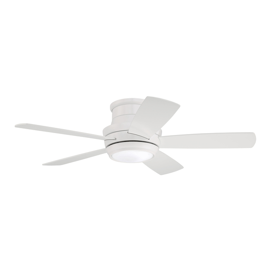
Tempo Hugger 44in.
Installation Guide
For Model:
TMPH44
E192641
net weight of fan: 18.58 lb (8.43 kg)
READ THESE INSTRUCTIONS
AND SAVE THEM FOR FUTURE USE
Table of Contents:
Safety Tips. pg. 2
Unpacking Your Fan. pg. 3
Parts Inventory. pg. 3
Installation Preparation. pg. 4
Mounting Plate Installation. pg. 4
Preparation for Wiring. pg. 5
Wiring. pgs. 5 - 6
Fan Assembly. pg. 6
Blade Assembly. pg. 7
Remote Control Operation. pg. 10
Testing Your Fan. pg. 10
Troubleshooting. pg. 11
Warranty. pg. 11
Parts Replacement. pg. 11
page 1
PRINTED IN CHINA
Advertisement
Table of Contents

Related Manuals for Craftmade Tempo Hugger 44


Summary of Contents for Craftmade Tempo Hugger 44
-
Page 1: Table Of Contents
READ THESE INSTRUCTIONS AND SAVE THEM FOR FUTURE USE Tempo Hugger 44in. Installation Guide Table of Contents: For Model: Safety Tips. pg. 2 TMPH44 Unpacking Your Fan. pg. 3 Parts Inventory. pg. 3 Installation Preparation. pg. 4 Mounting Plate Installation. pg. 4 Preparation for Wiring. -
Page 2: Safety Tips
SAFETY TIPS. WARNING: To reduce the risk of electrical shock, turn off the electricity to the fan at the main fuse box or circuit panel before you begin the fan installation or before servicing the fan or installing accessories. READ ALL INSTRUCTIONS AND SAFETY INFORMATION CAREFULLY BEFORE INSTALLING YOUR FAN AND SAVE THESE INSTRUCTIONS. CAUTION: To avoid personal injury, the use of gloves may be necessary while handling fan parts with sharp edges. -
Page 3: Unpacking Your Fan
1. Unpacking Your Fan. Carefully open the packaging. Remove items from Styrofoam inserts. Remove motor housing and place on carpet or Styrofoam to avoid damage to finish. Do not discard fan carton or Styrofoam inserts should this fan need to be returned for repairs. -
Page 4: Installation Preparation
3. Installation Preparation. blade edge To prevent personal injury and damage, ensure that the hanging location allows the blades a inches 7 feet (76cm) clearance of 7ft. (2.13m) from the floor and 30in. (2.13m) (76cm) from any wall or obstruction. This fan is suitable for room sizes up to 225 square 12 ft. -
Page 5: Preparation For Wiring
5. Preparation for Wiring. safety wood With wider opening facing up, place housing ring cable joist over top of motor housing. Then, push housing ring loop wood screw down past top edge of motor housing. and washer Lift motor housing to mounting plate and then hang motor housing on j-hook on underside of mounting plate. -
Page 6: Fan Assembly
6. Wiring. (cont.) Modifications not approved by the party responsible for compliance could void the user's authority to operate the equipment. [PLEASE NOTE: Wall and/or handheld remote *NOTE: This equipment has been tested and found to comply with the limits for a Class B digital device, pursuant to Part 15 of the FCC Rules. -
Page 7: Blade Assembly
8. Blade Assembly. WARNING: To reduce the risk of serious bodily injury, DO NOT use power tools to motor housing assemble the blades. If screws are overtightened, blades may crack and break. Time Saver: Washers for blade attachment screws can be set on each screw prior to installing blades. - Page 8 9. Light Kit Assembly (Optional). (cont.) Remove 1 screw from post on underside of fitter plate and partially loosen the other 2 motor screws. housing Connect WHITE wire from motor housing to WHITE wire from LED light kit. Connect BLACK fitter plate (or BLUE) wire from motor housing to BLACK wire from LED light kit.
-
Page 9: Assembly Of Handheld Remote Control
10. Assembly of Handheld Remote Control. IN ORDER TO USE THE HANDHELD REMOTE CONTROL, remote control PLEASE CONTINUE WITH SECTION 10 for remote control cover assembly instructions. If you have already installed the wall control but do not wish to use the handheld remote control, please proceed to Section 11. -
Page 10: Automated Learning Process./Activating Code
11. Automated Learning Process./Activating Code. CAUTION: The wall and/or handheld remote control can be programmed to multiple receivers or fans. If this is not desired, turn wall switch off to any other programmable receiver or fan. Restore electrical power and then, if using wall control, set slider switch on wall control to the ON position. -
Page 11: Troubleshooting
Service at 1-800-486-4892 to arrange for return of fan. 1. Check wall switch to fan/wall control. Return fan, shipping prepaid, to Craftmade. We will repair 2. Check to be sure wall control (optional use) is wired or ship you a replacement fan, and we will pay the return properly. -
Page 12: Guía De Instalación
LEER ESTAS INSTRUCCIONES Y GUARDARLAS PARA UTILIZACIÓN FUTURA Tempo Hugger 44in. Guía de instalación Para modelo: Índice de materias: TMPH44 Sugerencias de seguridad. Pág. 2 Desempaquetado del ventilador. Pág. 3 Inventario de piezas. Pág. 3 Preparación para la instalación. Pág. 4 Instalación de la placa de montaje. - Page 13 SUGERENCIAS DE SEGURIDAD. ADVERTENCIA: Para evitar la posibilidad de una descarga eléctrica, desconectar la corriente en la caja de fusibles principal o el interruptor protector antes de iniciar la instalación del ventilador o antes de repararlo o instalar accesorios. LEER TODAS LAS INSTRUCCIONES E INFORMACIÓN DE SEGURIDAD CUIDADOSAMENTE ANTES DE INSTALAR SU VENTILADOR Y GUARDAR ESTAS INSTRUCCIONES.
- Page 14 1. Desempaquetado del ventilador. Abrir el empaque cuidadosamente. Sacar los artículos del embalaje. Sacar el motor y ponerlo en una alfombra o en el embalaje para evitar rayar el acabado. Guardar la caja de cartón o el empaquetamiento original en caso de que tenga que mandar el ventilador para alguna reparación.
-
Page 15: Preparación Para La Instalación
3. Preparación para la instalación. borde del aspa Para prevenir daño corporal y otros daños, estar 76cm seguro de que el lugar en donde va a colgar el ventilador le permite un espacio libre de 2,13m 2,13m pulg.) (7 pies) (7 pies) entre las puntas de las aspas y el piso y 76cm (30 pulg.) entre las aspas y cualquier pared u otra obstrucción. -
Page 16: Instalación Eléctrica
5. Preparación para la instalación eléctrica. Poner el aro del bastidor en la parte superior del bastidor del bucle del motor, colocándolo para que la abertura más ancha esté cable de tornillo orientada hacia arriba. Luego, pasar el aro del bastidor por seguridad para madera debajo del borde superior del bastidor del motor. - Page 17 6. Instalación eléctrica. (cont.) Las modificaciones no aprobadas por la parte responsable de la conformidad [FAVOR DE DARSE CUENTA: Hay que utilizar el podrían invalidar la autorización del usuario para manejar el equipo. control de pared y/o el control remoto de mano *NOTA: Se han hecho pruebas en este equipo y se ha comprobado que cumple con los límites para un aparato digital de clase B, de acuerdo con la Parte 15 de las Reglas de la FCC.
-
Page 18: Instalación Del Juego De Luz (Opcional)
8. Colocación de las aspas. ADVERTENCIA: Para reducir el riesgo de lesiones corporales graves, NO utilizar herramientas eléctricas para ensamblar las aspas. Si aprieta demasiado los tornillos, las bastidor del motor aspas podrían agrietarse y quebrarse. Para ahorrar tiempo: Se pueden poner las arandelas en los tornillos que son para las aspas antes de colocar las aspas. - Page 19 9. Instalación del juego de luz (opcional). (cont.) Quitar 1 tornillo del poste que se encuentra en la parte inferior de la placa de conexión y bastidor parcialmente aflojar los otros 2 tornillos. del motor Conectar el cable BLANCO del juego de luz LED al cable BLANCO del bastidor del motor.
-
Page 20: Ensamblaje Del Control Remoto De Mano
10. Ensamblaje del control remoto de mano. PARA PODER UTILIZAR EL CONTROL REMOTO DE MANO, FAVOR DE SEGUIR CON LA SECCION 10 para armar el control remoto. Si cubierta del ya se instaló el control de pared pero no desea utilizar el control control remoto remoto de mano, favor de pasar a la sección 11. -
Page 21: Proceso De Aprendizaje Automático./El Activar El Código
11. Proceso de aprendizaje automático./El activar el código. PRECAUCIÓN: Se puede programar el control de pared/control remoto de mano para usar con varios receptores o ventiladores. Si no desea hacer esto, apagar el interruptor de cualquier otro receptor o ventilador programable. Conectar la electricidad y luego, si se instaló... -
Page 22: Localización De Fallas
Craftmade. Nosotros repararemos el motor al comprador o le enviaremos uno de reemplazo Problema: El juego de luz no se ilumina. y Craftmade pagará los gastos de envío de regreso. Soluciones: GARANTÍA LIMITADA DE 6 AÑOS hasta DE POR VIDA: 1.
Need help?
Do you have a question about the Tempo Hugger 44 and is the answer not in the manual?
Questions and answers