Table of Contents
Advertisement
Available languages
Available languages
Quick Links
10/ 100 /10
00M bps
Act ivity
1
1
2
2
3
3
4
4
5
5
6
6
7
7
8
8
9
9
10 11
10 11
12
12
10/ 100 /10
10/ 100 /10
00M bps
Act ivity
1
2
3
4
5
6
7
8
9
10 11
12
IES5120 SERIES INDUSTRIAL
SWITCHES
INDUSTRIELLE SWITCHES DER IES5120 SERIE
SWITCHS INDUSTRIELS DE LA SÉRIE IES5120
IES����シリーズ産業用スイッチ
Quick Start Guide
Quick Start Anleitung
Guide de Démarrage Rapide
クイックスタートガイド
13
13
141 5
141 5
161 7
161 7
181 9
181 9
202 1
202 1
222 3
222 3
24
24
Com bo
17
19
00B ASE -T
18
20
13
14 15
16 17
18 19
20 21
22 23
24
25
26
27
28 29
10/ 100 /10
00B ASE -T
V1.0
21
23
CO NSO LE
PW R1
PW R2
Alar m
SFP +
Dia g
22
24
25
26
27
28
30 31
32 33
34 35
36
37
38 39
40 41
42 43
44 45
46 47
IES 51 20 -28
TS
48
IES 512 0-4
8T 4S
CO NSO LE
PW R1
PW R2
Alar m
Diag
SFP +
49
50
51
52
Advertisement
Table of Contents

Related Manuals for FS IES5120 Series


Summary of Contents for FS IES5120 Series
- Page 1 IES 512 0-4 8T 4S CO NSO LE PW R1 PW R2 Alar m Diag SFP + IES5120 SERIES INDUSTRIAL SWITCHES INDUSTRIELLE SWITCHES DER IES5120 SERIE SWITCHS INDUSTRIELS DE LA SÉRIE IES5120 IES����シリーズ産業用スイッチ Quick Start Guide V1.0 Quick Start Anleitung Guide de Démarrage Rapide...
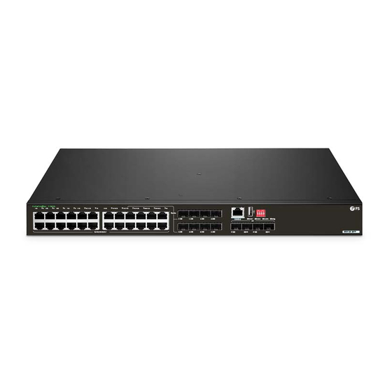
- Page 2 Introduction Thank you for choosing the IES5120 Series Industrial Switches. This guide is designed to familiarize you with the layout of the switches and describes how to deploy them in your network. 10/100/1000Mbps Activity 10 11 10 11 14 15...
-
Page 3: Hardware Overview
IES5120-28TS-P Grounding Cable x1 Mounting Bracket x2 M4 Screw x8 Rubber Pad x4 DC Power Cord x1 M6 Screw x4 NOTE: The accessories may vary from illustration, please prevail in kind. Hardware Overview Front Panel Ports IES5120-28TF CONSOLE COMBO 10/100/1000Mbps Activity 10 11 10 11... - Page 4 IES5120-28TS-P CONSOLE USB Delivering Power Fault 10 11 14 15 16 17 18 19 20 21 22 23 10/100/1000Mbps Activity CONSOLE PWR1 PWR2 Alarm Diag SFP+ IES5120-28TS-P PoE+ 10/100/1000BASE-T-PoE++ 10/100/1000BASE-T-PoE+ 10/100/1000BASE-T SFP+ IES5120-48T4S CONSOLE USB 10/100/1000Mbps Activity 10 11 14 15 16 17 18 19 20 21...
-
Page 5: Front Panel Leds
Front Panel LEDs IES5120-28TF PWR2 10/100/1000BASE-T PWR1 Alarm 10/100/1000Mbps Activity 10 11 10 11 1415 1415 1617 1617 1819 1819 2021 2021 2223 22 23 Combo Diag CONSOLE PWR1 PWR2 Alarm Diag IES5120-28TF 10/100/1000BASE-T IES5120-28TS PWR2 10/100/1000BASE-T PWR1 Alarm 10/100/1000Mbps Activity 10 11 10 11... - Page 6 State Description LEDs Solid Green The AC/DC power input is successful. The AC/DC power input is abnormal or the DC PWR1/PWR2 power input is not supplied. Solid Red The abnormalities occur in the data input interface. Alarm The device is running normally. The self-inspection of the system fails, or a system Solid Red operation alarm occurs.
-
Page 7: Dip Switch Description
DIP Switch IES5120-28TF 10/100/1000Mbps Activity 10 11 10 11 1415 1415 1617 1617 1819 1819 2021 2021 2223 2223 Combo CONSOLE PWR1 PWR2 Alarm Diag IES5120-28TF 10/100/1000BASE-T DIP Switch IES5120-28TS 10/100/1000Mbps Activity 10 11 10 11 1415 1415 1617 1617 1819 1819 2021... -
Page 8: Back Panel
Back Panel IES5120-28TF Grounding Point PWR1 PWR2 100-240V~ ; 50/60Hz; 1.0A 100-240V~ ; 50/60Hz; 1.0A PWR1 PWR2 IES5120-28TS Grounding Point PWR1 PWR2 100-240V~ ; 50/60Hz; 1.0A 100-240V~ ; 50/60Hz; 1.0A PWR1 PWR2 IES5120-28TS-P PWR1 PWR2 53-57V ;4.2A 53-57V ;4.2A Grounding Point PWR1 PWR2 IES5120-48T4S Grounding Point... -
Page 9: Installation Requirements
Installation Requirements Before the installation, make sure that you have the following Phillips screwdriver and athead screwdriver. ESD wrist strap. Needle-nose plier, diagonal plier, and crimping plier. Spanner wrench. Safety Precautions The power source should be removed before cleaning the device. Do not clean the device with liquid. -
Page 10: Mounting The Switch
Mounting the Switch Desk Mounting 10/ 100 /10 00M bps Acti vity 10 11 10 11 141 5 141 5 161 7 161 7 181 9 181 9 202 1 202 1 222 3 222 3 Com bo 10/1 00/1 000B ASE CON SOL PWR 1... -
Page 11: Grounding The Switch
2. Attach the switch to the rack with screws and cage nuts. Grounding the Switch PW R2 PW R1 z; 1. 0A ~ ; 50 /6 0H 10 0- 24 0V z; 1. 0A ~ ; 50 /6 0H 10 0- 24 0V 1. - Page 12 2. Connect the other end of the cable to the grounding bar. WARNING: 1. Correctly connecting the grounding cable is crucial to lightning protection and ESD and EMI protection. You must connect the grounding cable correctly and reliably. 2. Do not connect the positive and negative contacts of the DC power interface to the ground.
- Page 13 1. Strip o the PVC interface cable protector and the insulating layer of the two positive and negative power cables with 7mm bore wire, and the other end of the cables are the same. 2. Plug the DO and DI cables into the holes of the phoenix connector. 3.
-
Page 14: Connecting The Console Port
Connecting the SFP/SFP+Ports 1. Plug the compatible SFP/SFP+ transceiver into the SFP/SFP+ port. 2. Connect one end of a ber optic cable to the transceiver and the other end of the cable to another ber device. Connecting the Console Port 1. -
Page 15: Connecting The Power
Connecting the Power Connecting the AC Power Cord P W R 2 P W R 1 z; 1. 0A ~ ; 50 /6 0H 10 0- 24 0V z; 1. 0A ~ ; 50 /6 0H 10 0- 24 0V 1. -
Page 16: Connecting The Dc Power Cord
Connecting the DC Power Cord P W R 2 P W R 1 ;4 .2 A 5 3 -5 7 V ;4 .2 A 5 3 -5 7 V 1. Insert the wires into the terminal block, with the positive wire to the positive connection, and the negative wire to the negative connection. - Page 17 Validate settings upon exit A d v a n c e d . . . Cancel Step 3: Open a web browser, type http://192.168.1.1, and enter the default username and password, admin/admin. FS SWITCH WELCOME TO Username Please enter the username Password...
-
Page 18: Troubleshooting
Con guring the Switch Using the Console Port Step 1: Connect a computer to the console port of the switch using the console cable. Step 2: Start the terminal simulation software, such as HyperTerminal on the computer. Step 3: Set the parameters of the HyperTerminal: Baud rate to 115200, Data bits to 8, Parity to None, and Stop bits to 1. -
Page 19: Online Resources
Product Warranty FS ensures our customers that for any damage or faulty items due to our workmanship, we will o er a free return within 30 days from the day you receive your goods. This excludes any custom-made items or tailored solutions. - Page 20 Einführung Vielen Dank, dass Sie sich für die Industrie-Switches der Serie IES5120 entschieden haben. Diese Anleitung soll Sie mit dem Aufbau der Switches vertraut machen und beschreibt, wie Sie sie in Ihrem Netzwerk einsetzen können. 10/100/1000Mbps Activity 10 11 10 11 14 15 14 15 1617...
- Page 21 HINWEIS: Dieses Netzkabel kann nicht mit anderen Geräten verwendet werden, und andere Netzkabel sollten nicht mit diesem Gerät verwendet werden. IES5120-28TS-P Erdungskabel x1 Montagewinkel x2 M4-Schraube x8 M6-Schraube x4 Gummipad x4 D-Netzkabel x1 HINWEIS: Bitte beachten Sie, dass das Zubehör von der Abbildung abweichen kann. Hardware-Übersicht Ports an der Vorderseite IES5120-28TF...
- Page 22 IES5120-28TS-P CONSOLE USB Delivering Power Fault 10 11 14 15 16 17 18 19 20 21 22 23 10/100/1000Mbps Activity CONSOLE PWR1 PWR2 Alarm Diag SFP+ IES5120-28TS-P PoE+ 10/100/1000BASE-T-PoE++ 10/100/1000BASE-T-PoE+ SFP+ 10/100/1000BASE-T IES5120-48T4S CONSOLE USB 10/100/1000Mbps Activity 10 11 14 15 16 17 18 19 20 21...
-
Page 23: Leds An Der Vorderseite
LEDs an der Vorderseite IES5120-28TF PWR2 10/100/1000BASE-T PWR1 Alarm 10/100/1000Mbps Activity 10 11 10 11 1415 1415 1617 1617 1819 1819 2021 2021 2223 22 23 Combo Diag CONSOLE PWR1 PWR2 Alarm Diag IES5120-28TF 10/100/1000BASE-T IES5120-28TS PWR2 10/100/1000BASE-T PWR1 Alarm 10/100/1000Mbps Activity 10 11... - Page 24 LEDs Status Beschreibung Durchgehend grün Die AC/DC-Stromzufuhr ist ordnungsgemäß. PWR1/PWR2 Der AC/DC-Stromeingang ist fehlerhaft oder der DC-Stromeingang ist nicht angeschlossen. Die Störungen treten an der Durchgehend rot Dateneingangsschnittstelle auf. Alarm Das Gerät läuft normal. Die Selbstinspektion des Systems schlägt fehl, Durchgehend rot oder es tritt ein Systembetriebsalarm auf.
-
Page 25: Dip-Schalter
DIP-Schalter IES5120-28TF 10/100/1000Mbps Activity 10 11 10 11 1415 1415 1617 1617 1819 1819 2021 2021 2223 22 23 Combo CONSOLE PWR1 PWR2 Alarm Diag IES5120-28TF 10/100/1000BASE-T DIP-Schalter IES5120-28TS 10/100/1000Mbps Activity 10 11 10 11 1415 1415 1617 1617 1819 1819 2021 2021... - Page 26 Rückseite IES5120-28TF Erdungspunkt PWR1 PWR2 100-240V~ ; 50/60Hz; 1.0A 100-240V~ ; 50/60Hz; 1.0A PWR1 PWR2 IES5120-28TS Erdungspunkt PWR1 PWR2 100-240V~ ; 50/60Hz; 1.0A 100-240V~ ; 50/60Hz; 1.0A PWR1 PWR2 IES5120-28TS-P PWR1 PWR2 53-57V ;4.2A 53-57V ;4.2A Erdungspunkt PWR1 PWR2 IES5120-48T4S Erdungspunkt PWR1 PWR2...
- Page 27 Installationsvoraussetzungen Stellen Sie vor der Installation sicher, dass Sie Folgendes haben: Kreuzschlitzschraubendreher und Schlitzschraubendreher ESD-Armband Spitzzange, Schrägzange und Crimpzange Schraubenschlüssel Sicherheitsvorkehrungen Vor dem Reinigen des Geräts sollte die Stromquelle entfernt werden. Reinigen Sie das Gerät nicht mit Flüssigkeit. Achten Sie darauf, dass der Switch waagerecht und stabil steht, um gefährliche Situtationen zu vermeiden.
-
Page 28: Montage Des Switches
Montage des Switches Tisch-Montage 10/ 100 /10 00M bps Acti vity 10 11 10 11 141 5 141 5 161 7 161 7 181 9 181 9 202 1 202 1 222 3 222 3 Com bo 10/1 00/1 000B ASE CON SOL PWR 1 PWR 2... - Page 29 2. Befestigen Sie den Switch mit Schrauben und Kä gmuttern am Rack. Erdung des Switches PW R2 PW R1 z; 1. 0A ~ ; 50 /6 0H 10 0- 24 0V z; 1. 0A ~ ; 50 /6 0H 10 0- 24 0V 1.
- Page 30 2. Schließen Sie das andere Ende des Kabels an die Erdungsschiene an. 2. Schließen Sie das andere Ende des Kabels an die Erdungsschiene an. WARNUNG: 1. der korrekte Anschluss des Erdungskabels ist entscheidend für den Blitzschutz sowie den ESD- und EMI-Schutz. Sie müssen das Erdungskabel korrekt und zuverlässig anschließen.
- Page 31 1. Entfernen Sie den PVC-Kabelschutz und die Isolierschicht der beiden positiven und negativen Stromkabel mit 7 mm Bohrdraht. Das andere Ende der Kabel sollte gleich sein. 2. Stecken Sie die DO- und DI-Kabel in die Löcher des Anschluss-Klemmblocks. 3. Ziehen Sie die beiden Schrauben an der Oberseite des Anschluss-Klemmblocks mit einem Schlitzschraubendreher im Uhrzeigersinn fest.
- Page 32 Anschließen der SFP/SFP+-Ports 1. Stecken Sie den kompatiblen SFP/SFP+-Transceiver in den SFP/SFP+-Port. 2. Schließen Sie ein Ende eines Glasfaserkabels an den Transceiver und das andere Ende des Kabels an ein anderes Glasfasergerät an. Anschließen des Console-Ports 1. Stecken Sie den RJ45-Stecker des Console-Kabels in den RJ45-Console-Port des Switches. 2.
-
Page 33: Anschließen Der Stromversorgung
Anschließen der Stromversorgung Anschließen des AC-Netzkabels P W R 2 P W R 1 z; 1. 0A ~ ; 50 /6 0H 10 0- 24 0V z; 1. 0A ~ ; 50 /6 0H 10 0- 24 0V 1. Befestigen Sie die Netzkabel xierer an den seitlichen Ö nungen des Netz-Ports. 2. - Page 34 Anschließen des DC-Netzkabels P W R 2 P W R 1 ;4 .2 A 5 3 -5 7 V ;4 .2 A 5 3 -5 7 V 1. Führen Sie die Drähte in den Klemmenblock ein, wobei der positive Draht an den positiven Anschluss und der negative Draht an den negativen Anschluss angeschlossen wird.
- Page 35 A d v a n c e d . . . Cancel Schritt 3: Ö nen Sie einen Webbrowser, geben Sie http://192.168.1.1 ein, und geben Sie den Standard-Benutzernamen und das Standard-Passwort admin/admin ein. FS SWITCH WELCOME TO Username Please enter the username...
-
Page 36: Fehlerbehebung
Kon gurieren des Switches über den Console-Port Schritt 1: Schließen Sie einen Computer über das Console-Kabel an den Console-Port des Switches an. Schritt 2: Starten Sie die Terminalsimulationssoftware, z. B. HyperTerminal, auf dem Computer. Schritt 3: Stellen Sie die Parameter von HyperTerminal ein: Baud rate auf 115200, Data bits auf 8, Parity auf None und Stop bits auf 1. -
Page 37: Fehlerbehebung Im Kon Gurationssystem
Kontakt https://www.fs.com/de/contact_us.html Produktgarantie FS garantiert seinen Kunden, dass wir bei Schäden oder fehlerhaften Artikeln, die auf unsere Verarbeitung zurückzuführen sind, eine kostenlose Rückgabe innerhalb von 30 Tagen nach Erhalt der Ware anbieten. Dies gilt nicht für Sonderanfertigungen oder maßgeschneiderte Lösungen. - Page 38 Introduction Nous vous remercions d'avoir choisi le switch industriel de la série IES5120. Ce guide est conçu pour vous familiariser avec la con guration du switch et décrit comment procéder à son déploiement. 10/100/1000Mbps Activity 10 11 10 11 14 15 14 15 1617 1617...
-
Page 39: Présentation Du Matériel
NOTE : Ce cordon d'alimentation ne peut pas être utilisé avec d'autres appareils, et les autres cordons d'alimentation ne doivent pas être utilisés avec cet appareil. IES5120-28TS-P Câble de Mise à la Terre x1 Support de Montage x2 Vis M4 x8 Pad en Caoutchouc x4 Câble d'Alimentation DC x1 Vis M6 x4... - Page 40 IES5120-28TS-P CONSOLE USB Delivering Power Fault 10 11 14 15 16 17 18 19 20 21 22 23 10/100/1000Mbps Activity CONSOLE PWR1 PWR2 Alarm Diag SFP+ IES5120-28TS-P PoE+ 10/100/1000BASE-T-PoE++ 10/100/1000BASE-T-PoE+ 10/100/1000BASE-T SFP+ IES5120-48T4S CONSOLE USB 10/100/1000Mbps Activity 10 11 14 15 16 17 18 19 20 21...
- Page 41 LED du Panneau Frontal IES5120-28TF PWR2 10/100/1000BASE-T PWR1 Alarm 10/100/1000Mbps Activity 10 11 10 11 1415 1415 1617 1617 1819 1819 2021 2021 2223 22 23 Combo Diag CONSOLE PWR1 PWR2 Alarm Diag IES5120-28TF 10/100/1000BASE-T IES5120-28TS PWR2 10/100/1000BASE-T PWR1 Alarm 10/100/1000Mbps Activity 10 11...
- Page 42 État Description Vert L'entrée d'alimentation AC/DC est bien e ectuée. L'entrée d'alimentation AC/DC présente une PWR1/PWR2 anomalie ou l'entrée d'alimentation DC n'est pas Éteint alimentée. Rouge L'interface de données présente une anomalie. Alarm L'appareil fonctionne normalement. Éteint L'auto-inspection du système échoue ou une Rouge alarme de fonctionnement du système se produit.
- Page 43 Interrupteur DIP IES5120-28TF 10/100/1000Mbps Activity 10 11 10 11 1415 1415 1617 1617 1819 1819 2021 2021 2223 22 23 Combo CONSOLE PWR1 PWR2 Alarm Diag IES5120-28TF 10/100/1000BASE-T Interrupteur DIP IES5120-28TS 10/100/1000Mbps Activity 10 11 10 11 1415 1415 1617 1617 1819 1819...
-
Page 44: Panneau Arrière
Panneau Arrière IES5120-28TF Mise à la Terre PWR1 PWR2 100-240V~ ; 50/60Hz; 1.0A 100-240V~ ; 50/60Hz; 1.0A PWR1 PWR2 IES5120-28TS Mise à la Terre PWR1 PWR2 100-240V~ ; 50/60Hz; 1.0A 100-240V~ ; 50/60Hz; 1.0A PWR1 PWR2 IES5120-28TS-P PWR1 PWR2 53-57V ;4.2A 53-57V ;4.2A... -
Page 45: Conditions D'installation
Conditions d'Installation Avant l'installation, assurez-vous que vous disposez des éléments suivants Tournevis cruciforme et tournevis plat. Bracelet ESD. Pince à bec e lé, pince diagonale et pince à sertir. Clé à molette. Précautions de Sécurité La source d'alimentation doit être retirée avant de nettoyer l'appareil. Ne pas nettoyez l'appareil avec du liquide. -
Page 46: Installation En Rack
Installation du Switch Montage sur Bureau 10/ 100 /10 00M bps Acti vity 10 11 10 11 141 5 141 5 161 7 161 7 181 9 181 9 202 1 202 1 222 3 222 3 Com bo 10/1 00/1 000B ASE CON SOL PWR 1... - Page 47 2. Fixez le switch au rack à l'aide des vis et des écrous à cage. Mise à la Terre du Switch PW R2 PW R1 z; 1. 0A ~ ; 50 /6 0H 10 0- 24 0V z; 1. 0A ~ ;...
- Page 48 2. Connectez l'autre extrémité du câble à la barre de mise à la terre. AVERTISSEUR : 1. La connexion correcte du câble de mise à la terre est cruciale pour la protection contre la foudre et la protection contre les décharges électrosta- tiques (ESD) et les interférences électromagnétiques (EMI).
- Page 49 1. Dénudez le protecteur de câble d'interface en PVC et la couche isolante des deux câbles d'alimentation positif et négatif avec un l de 7 mm, et l'autre extrémité des câbles est la même. 2. Branchez les câbles DO et DI dans les trous du connecteur phoenix. 3.
- Page 50 Connexion des Ports SFP/SFP+ 1. Branchez l'émetteur-récepteur SFP/SFP+ compatible dans le port SFP/SFP+. 2. Connectez une extrémité d'un câble à bre optique à l'émetteur-récepteur et l'autre extrémité du câble à un autre dispositif à bre optique. Connexion du Port Console 1.
-
Page 51: Branchement De L'alimentation
Branchement de l'Alimentation Branchement du Câble d'Alimentation CA (Courant Alternatif) P W R 2 P W R 1 z; 1. 0A ~ ; 50 /6 0H 10 0- 24 0V z; 1. 0A ~ ; 50 /6 0H 10 0- 24 0V 1. - Page 52 Branchement du Câble d'Alimentation CC (Courant Continu) P W R 2 P W R 1 ;4 .2 A 5 3 -5 7 V ;4 .2 A 5 3 -5 7 V 1. Insérez les ls dans le bornier, en plaçant le l positif sur la conn le l négatif sur la connexion négative.
- Page 53 A d v a n c e d . . . Cancel Étape 3 : Ouvrez un navigateur web, tapez http://192.168.1.1, et entrez le nom d'utilisateur et le mot de passe de défaut, admin/admin. FS SWITCH WELCOME TO Username Please enter the username...
-
Page 54: Dépannage
Con guration du Switch à l'Aide du Port Console Étape 1 : Connectez un ordinateur au port de console du switch à l'aide du câble de console. Étape 2 : Lancez le logiciel de simulation HyperTerminal sur l'ordinateur. Étape 3 : Dé nissez les paramètres de l'HyperTerminal : Baud rate à 115200, Data bits à 8, Parity à... -
Page 55: Garantie Du Produit
Garantie du Produit FS garantit à ses clients que tout article endommagé ou défectueux en raison de sa fabrication pourra être retourné gratuitement dans un délai de 30 jours à compter de la date de réception de la marchandise. Cette garantie ne s'applique pas aux articles fabriqués sur mesure ou aux solutions personnalisées. - Page 56 イン トロダクション このたびは、 IES����シリーズ産業用スイッチをお買いあげいただき、 誠にありがとうございます。 本 ガイドは、 IES����シリーズ産業用スイッチの概要とネッ トワークへの導入方法について説明します。 ��/���/����Mbps Activity � � � � � � � � � � � � � � � � � � �� �� �� �� �� �� �� �� �� �� �� �� ��...
- Page 57 注: この電源コードは他の機器には使用できません。また、他の電源コードはこの機 器に使用しないでください。 IES5120-28TS-P アースケーブル x� マウン トブラケッ ト x� M�ネジ x� ゴムパッ ド x� DC電源コード x� M�ネジ x� 注: アクセサリーの図は参考用です。 ハードウェアの概要 フロントパネルのポート IES5120-28TF CONSOLE COMBO 10/100/1000Mbps Activity 10 11 10 11 1415 1415 1617 1617 1819 1819 2021 2021 2223 2223 Combo...
- Page 58 IES5120-28TS-P CONSOLE USB Delivering Power Fault 10 11 14 15 16 17 18 19 20 21 22 23 10/100/1000Mbps Activity CONSOLE PWR1 PWR2 Alarm Diag SFP+ IES5120-28TS-P PoE+ 10/100/1000BASE-T-PoE++ 10/100/1000BASE-T-PoE+ 10/100/1000BASE-T SFP+ IES5120-48T4S CONSOLE USB 10/100/1000Mbps Activity 10 11 14 15 16 17 18 19 20 21...
- Page 59 フロントパネルのLED IES5120-28TF PWR2 10/100/1000BASE-T PWR1 Alarm 10/100/1000Mbps Activity 10 11 10 11 1415 1415 1617 1617 1819 1819 2021 2021 2223 22 23 Combo Diag PWR1 PWR2 Alarm Diag CONSOLE IES5120-28TF 10/100/1000BASE-T IES5120-28TS PWR2 10/100/1000BASE-T PWR1 Alarm 10/100/1000Mbps Activity 10 11 10 11 1415 1415...
- Page 60 状態 説明 点灯(緑) AC/DC電源の入力に成功しています AC/DC電源の入力に異常があるか、 DC電源入力 PWR�/PWR� 消灯 が供給されていません。 データ入力インターフェースに異常が発生してい 点灯(赤) ます。 Alarm デバイスは正常に動作しています。 消灯 システムの自己点検に失敗したか、 システム動作ア 点灯(赤) ラームが発生しています。 Diag システムの自己点検は成功し、 デバイスは正常に動 消灯 作しています。 点灯(赤) ポートは接続されています。 ��/���/����BASE-T 点滅(緑) データが受信または送信されています。 (IES����-��TF/ IES����-��TS/ ポートは接続されていません。 消灯 IES����-��T�S) ポートは��/���/����Mbpsで接続されています。 点灯 データが��/���/����Mbpsで受信または送信され 点減 緑 ています。 ポートが切断されているか、...
- Page 61 DIPスイッチ IES5120-28TF ��/���/����Mbps Activity � � � � � � � � � � � � � � � � � � �� �� �� �� �� �� �� �� �� �� �� �� �� �� �� �� �� �� ��...
- Page 62 バックパネル IES5120-28TF 接地点 PWR� PWR� ���-���V~ ; ��/��Hz; �.�A ���-���V~ ; ��/��Hz; �.�A PWR� PWR� IES����-��TS 接地点 PWR� PWR� ���-���V~ ; ��/��Hz; �.�A ���-���V~ ; ��/��Hz; �.�A PWR� PWR� IES����-��TS-P PWR� PWR� ��-��V ;�.�A ��-��V ;�.�A PWR� PWR� 接地点 IES����-��T�S 接地点...
- Page 63 設置要件 設置の前に、 以下の道具が準備してあることを確認して ください。 プラスドライバーとマイナスドライバー 静電気防止リス トバンド ニードルノーズプライヤー、 ダイアゴナルプライヤー、 圧着プライヤー スパナ/レンチ 注意事項 デバイスをクリーニングする前に、 電源を取り外す必要があります。 また、 液体でデバイスをクリ ーニングしないでください。 危険な状態を避けるため、 スイッチが水平で安定した状態であることを確認して ください。 スイッチは適切な電圧のもとで正常に動作するため、 動作電圧がスイッチに記された電圧と一 致していることを確認して ください。 静電気による単板の損傷を防ぐため、 インターフェイスボードを交換する際は静電気防止リスト バンドを着用して ください。 光による損傷を避けるため、 装置が作動しているときは、 光インターフェイスを直接のぞかない でください。 感電の危険性を減らすため、 作業中はスイッチの筐体を取り外さず、 電源が入っていない場合で もむやみに取り外さないでください。 設置環境 スイッチの放熱のために、 スイッチの入口と出口にスペースがあることを確認して ください。 ラックは、...
- Page 64 スイッチの設置 デスクマウント 10/ 100 /10 00M bps Acti vity 10 11 10 11 141 5 141 5 161 7 161 7 181 9 181 9 202 1 202 1 222 3 222 3 Com bo 10/1 00/1 000B ASE CON SOL PWR 1 PWR 2 Alar m...
- Page 65 �. スイッチをネジとケージナッ トでラックに取り付けます。 スイッチの接地 PW R2 PW R1 z; 1. 0A ~ ; 50 /6 0H 10 0- 24 0V z; 1. 0A ~ ; 50 /6 0H 10 0- 24 0V �. アースケーブルの一端をスイッチの接地点に接続します。...
- Page 66 �. アースケーブルのもう一方の端を接地バーに接続します。 警告: �.アースケーブルの接続は、雷保護、ESDおよびEMI保護のため非常に重要で す。アースケーブルを正しく確実に接続してください。 �. DC電源インターフェースのプラスとマイナスの接点をアースに接続しないでくだ さい。アースネジとアースケーブルでスイッチを接地してください。 �. アースケーブルを機器室のアースストリップに接続してください。消火主管や避 雷針に接続しないでください。 �. 図の電源とアースポイントの位置は参考用です。 DO/DIポートケーブルの接続...
- Page 67 �.PVC インターフェイスケーブルプロテクターと、 �mmワイヤのプラス/マイナス�本の電源ケーブル の絶縁層を剥がします。 インターフェイスケーブルのもう一端も同様に行います。 �. DOケーブルとDIケーブルをフェニックスコネクターの穴に差し込みます。 �. フェニックスコネクタ上部の�本のネジをマイナスドライバーで時計回りに締めます。 �. フェニックスコネクタをスイッチのDO/DIポートに接続し、 DOケーブルとDIケーブルのもう一方を 別のデバイスに接続します。 RJ��ポートの接続 �. イーサネッ トケーブルの一端をIPカメラ、 IP電話、 アクセスポイン ト (AP) 、 その他のネッ トワーク機 器のRJ��ポートに接続します。 �. イーサネッ トケーブルのもう一方の端をスイッチのRJ��ポートに接続します。...
- Page 68 SFP/SFP+ポートの接続 �. 互換性のあるSFP/SFP+モジュールをSFP/SFP+ポートに挿入します。 �. 光ファイバーケーブルの一端をモジュールに接続し、 もう一端を別のファイバーデバイスに接続し ます。 コンソールポートの接続 �. コンソールケーブルの RJ��コネクタをスイッチの RJ��コンソールポートに挿入します。 �. コンソールケーブルのもう一方の端をコンピュータのシリアルポートに接続します。...
- Page 69 電源の接続 AC電源ケーブルの接続 P W R 2 P W R 1 z; 1. 0A ~ ; 50 /6 0H 10 0- 24 0V z; 1. 0A ~ ; 50 /6 0H 10 0- 24 0V �. 電源ケーブル固定具をAC電源ポートの横の穴に取り付けます。 �. 電源ケーブル固定具を上に引き上げます。 �. AC電源ケーブルの一端をAC電源ポートに差し込みます。 P W R 2 P W R 1 z;...
- Page 70 DC電源ケーブルの接続 P W R 2 P W R 1 ;4 .2 A 5 3 -5 7 V ;4 .2 A 5 3 -5 7 V �. プラス線をプラス接続に、 マイナス線をマイナス接続にして、 ワイヤーを端子台に挿入します。 �. ワイヤークランプネジを締めます。...
- Page 71 Alternate DNS server: Validate settings upon exit A d v a n c e d . . . Cancel ステップ�: ブラウザで 「http://���.���.�.�」 と入力し、 デフ ォルトのユーザー名とパスワード 「 admin/admin」 を入力します。 FS SWITCH WELCOME TO Username Please enter the username Password Please enter the password LOGIN ステップ�: 「Login」...
- Page 72 コンソールポートからの設定 ステップ� : コンソールケーブルを使用して、 コンピュータをスイッチのコンソールポートに接続します。 ステップ� : コンピュータ上でHyperTerminalなどのターミナルエミュレータを起動します。 ステップ� : HyperTerminalのパラメータで、 ボーレート(Baud rate)を������、 データビッ ト(Data bits)を�、 パリティ(Parity)をなし(None)、 ストップビッ ト(Stop bits)を�に設定します。 Quick Connect Protocol: Serial The port may be manually entered or selected from the list. Port: COM5 USB Serial Port Flow Control 115200 Baud rate:...
- Page 73 : �、 パリティ(Parity) : なし(None)、 ストップビッ ト(Stop bits) : �、 フロー制御(flow control) : なし (NA)。 オンラインリソース ダウンロード https://www.fs.com/jp/products_support.html ヘルプセンター https://www.fs.com/jp/service/fs_support.html お問い合わせ https://www.fs.com/jp/contact_us.html 製品保証 FSは、 当社の管理による破損や不良品があった場合、 お客様のお手元に商品が届いてから��日以内 であれば、 特注品やオーダーメイドを除き、 無料で返品及び交換を承ります。 保証 : この製品は、 材料または製造上の欠陥に対して�年間の限定保証を提供いたします。 � 保証の詳細については、 下記をご参照ください。 ttps://www.fs.com/jp/policies/warranty.html 返品 ・ 交換 : 返品及び交換を希望される場合、 方法については下記をご参照ください https://www.fs.com/jp/policies/day_return_policy.html...
-
Page 74: Compliance Information
2014/35/EU, 2011/65/EU und (EU)2015/863 konform ist. Eine Kopie der EU-Konformitätserklärung nden Sie unter www.fs.com/de/company/quality_control.html. FS.COM GmbH déclare par la présente que ce dispositif est conforme à la Directive 2014/30/EU, 2014/35/EU, 2011/65/EU et (EU)2015/863. Une copie de la Déclaration de Conformité de l'UE est disponible à l'adresse suivante... - Page 75 2011/65/EU und (EU)2015/863 konform ist. Eine Kopie der EU-Konformitätserklärung nden Sie unter www.fs.com/de/company/quality_control.html. FS.COM GmbH déclare par la présente que ce dispositif est conforme à la Directive 2014/30/EU, 2011/65/EU et (EU)2015/863. Une copie de la Déclaration de Conformité de l'UE est disponible à l'adresse suivante https://www.fs.com/fr/company/quality_control.html.
-
Page 76: Waste Electrical And Electronic Equipment (Weee)
IES5120-28TS-P Hereby, FS.COM Innovation Ltd declares that this device is in compliance with the Directive SI 2016 No. 1091, SI 2012 NO. 3032. FS.COM INNOVATION LTD Unit 8, Urban Express Park, Union Way, Aston, Birmingham, B6 7FH, United Kingdom ISED... - Page 77 To avoid the potential e ects on the environment and human health as a result of the presence of hazardous substances in electrical and electronic equipment, end users of electrical and electronic equipment should understand the meaning of the crossed-out wheeled bin symbol. Do not dispose of WEEE as unsorted municipal wasteand have to collect such WEEE separately.
- Page 78 Alarm SFP+ Diag IES5120 SERIES INDUSTRIAL SWITCHES INDUSTRIELLE SWITCHES DER IES5120 SERIE SWITCHS INDUSTRIELS DE LA SÉRIE IES5120 IES����シリーズ産業用スイッチ Quick Start Guide V1.0 Quick Start Anleitung Guide de Démarrage Rapide Q.C. PASSED クイックスタートガイド Copyright © 2023 FS.COM All Rights Reserved.
Need help?
Do you have a question about the IES5120 Series and is the answer not in the manual?
Questions and answers