Table of Contents
Advertisement
Available languages
Available languages
Quick Links
Advertisement
Table of Contents

Related Manuals for FS IES5110-20FMS


Summary of Contents for FS IES5110-20FMS
- Page 1 IES5110-20FMS L3 MANAGED INDUSTRIAL SWITCH L3 MANAGED INDUSTRIELLER SWITCH SWITCH INDUSTRIEL MANAGEABLE L3 L�マネージド産業用スイッチ Quick Start Guide V1.0 Quick Start Anleitung Guide de Démarrage Rapide クイックスタートガイド...
- Page 2 Introduction Thank you for choosing the IES5110-20FMS Managed Industrial Switch. This guide is designed to familiarize you with the layout of the switch and describes how to deploy it in your network. IES5110-20FMS Accessories Console Cable x1 AC Power Cord x1...
-
Page 3: Hardware Overview
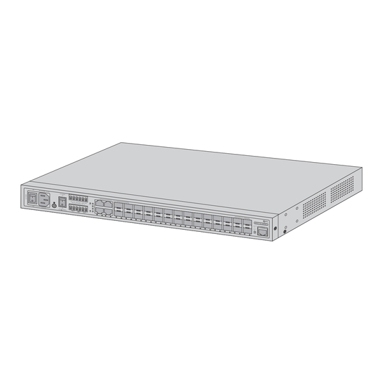
Hardware Overview Front Panel Ports RJ45 SFP+ CONSOLE Ports Description RJ45 10/100/1000BASE-T ports for Ethernet connection 1~14 for 100/1000BASE-X SFP ports, 15~24 for 100/1000/2500BASE-X SFP ports SFP+ SFP+ ports for 10G connection Console An RJ45 console port for serial management NOTE: The four RJ45 ports and the rst four SFP ports (1~4) together form the Combo ports. - Page 4 LEDs State Description Green AC power input has power. Green DC power input 1 has power. Green DC power input 2 has power. System Fault The switch DC or port has failed. Ring Green The ERPS Ring has been created successfully. DI/DO Blinking The switch DC or port has failed or DI has an event.
-
Page 5: Installation Requirements
Front Panel Button AC POWER DC POWER RESET SWITCH SWITCH Button Description Press the button for less than 5 seconds to reboot the switch. Press it for Reset more than 5 seconds to restore factory default con guration. AC/DC Power Switch ON means the power is switched on, while OFF means the power is cut o . -
Page 6: Mounting The Switch
Mounting the Switch Desk Mounting Place the switch on the desktop or the shelf near an AC power source. Rack Mounting 1. Secure the mounting brackets to the two sides of the switch with supplied screws. - Page 7 2. Attach the switch to the rack using the screws. NOTE: Please ensure good ventilation when the device is running. Grounding the Switch 1. Connect one end of the grounding cable to a proper earth ground, such as the rack in which the switch is mounted.
- Page 8 Connecting the RJ45 Ports 1. Connect an Ethernet cable to the RJ45 port of a network device. 2. Connect the other end of the Ethernet cable to the RJ45 port of the switch. Connecting the SFP/SFP+ Ports 1. Remove the dust plugs rst. 2.
- Page 9 Connecting the Console Port 1. Insert the RJ45 connector into the RJ45 console port on the front panel of the switch. 2. Connect the DB9 female connector of the console cable to the serial port on the computer. Connecting the AC Power 1.
- Page 10 Connecting the DC Power The 6-contact terminal block connector on the front panel of the switch is used for two DC redundant power inputs. 1. Insert positive/negative DC power wires into Contacts 1 and 2 for DC POWER 1, or 5 and 6 for DC POWER 2.
- Page 11 Wiring the Fault Alarm Contact Fault Faulty Alarm Contacts The Faulty Alarm Contacts are energized (CLOSE) for normal operation and will OPEN when a failure occurs. Insert the wires into the faulty alarm contacts. NOTE: 1. The fault alarm contacts are in the middle (3 & 4) of the terminal block connector. 2.
- Page 12 The 6-contact terminal block connector on the front panel of the switch is used for Digital Input and Digital Output. 1. The switch o ers two DI and DO groups. 1 and 2 are DI groups, 3 and 4 are DO groups, and 5 and 6 are GND (ground).
- Page 13 Power Source Sprinkler System 4. Wire DO0 and DO1 to Open Detector. NOTE: The two digital output groups are used to sense the switch port failure or power failure and issue a high or low signal to an external device.
- Page 14 Con guring the Switch Con guring the Switch Using the Console Port Step 1: Connect a computer to the console port of the switch with the console cable. Step 2: Start the terminal simulation software, such as HyperTerminal on the computer. Step 3: Set the parameters of the HyperTerminal: Baud rate to 115200, Data bits to 8, Parity to None, and Stop bits to 1.
- Page 15 Con guring the Switch Using the Web-Based Interface Step 1: Connect a computer to the Ethernet port of the switch using the network cable. Step 2: Set the IP address of the computer to 192.168.1.x ("x" is any number from 2 to 254). I nter net Protocol Version 4 ( TCP / IP v4) Prop er t ies General Yo u c a n g e t I P s e t t i n g s a s s i g n e d a u t o m a t i c a l l y i f y o u r n e t w o r k...
-
Page 16: Troubleshooting
Troubleshooting The Link Led Is Not Lit. Check the cable connection and remove the duplex mode of the switch. Some Stations Cannot Talk to Other Stations Located on the Other Port. Please check the VLAN settings, trunk settings, or port enabled/disabled status. Performance Is Bad. -
Page 17: Online Resources
Product Warranty FS ensures our customers that for any damage or faulty items due to our workmanship, we will o er a free return within 30 days from the day you receive your goods. This excludes any custom-made items or tailored solutions. - Page 18 Einführung Vielen Dank, dass Sie sich für den IES5110-20FMS Managed Industriellen Switch entschieden haben. Diese Anleitung soll Sie mit dem Aufbau des Switches vertraut machen und zeigt Ihnen, wie Sie den Switch in Ihrem Netzwerk einsetzen. IES5110-20FMS Zubehör Console-Kabel x1 AC-Netzkabel x1 Rack-Montage-Zubehörsatz x1...
- Page 19 Hardware-Übersicht Ports an der Vorderseite RJ45 SFP+ CONSOLE Port Beschreibung RJ45 10/100/1000BASE-T Ports für Ethernet-Verbindung 1~14 für 100/1000BASE-X SFP-Ports, 15~24 für 100/1000/2500BASE-X SFP-Ports SFP+ SFP+-Ports für 10G-Verbindung Console Ein RJ45-Console-Port für serielles Management HINWEIS: Die vier RJ45-Ports und die ersten vier SFP-Ports (1~4) bilden zusammen die Combo-Ports.
- Page 20 Status Beschreibung Grün Der AC-Netzeingang hat Strom. Grün Der DC-Netzeingang 1 hat Strom. Grün Der DC-Netzeingang 2 hat Strom. System Fault Der Switch DC oder der Port ist fehlerhaft. Ring Grün Der ERPS-Ring wurde erfolgreich erstellt. Der Switch DC oder der Port ist fehlerhaft oder DI meldet DI/DO Blinkt ein Ereignis.
- Page 21 Taste an der Vorderseite AC POWER DC POWER RESET SWITCH SWITCH Taste Beschreibung Drücken Sie die Taste für weniger als 5 Sekunden, um den Switch neu zu Reset starten. Drücken Sie die Taste länger als 5 Sekunden, um die Werkseinstellungen wiederherzustellen. ON bedeutet, dass der Strom eingeschaltet ist.
-
Page 22: Montage Des Switches
Montage des Switches Schreibtisch-Montage Stellen Sie den Switch auf den Schreibtisch oder in ein Regal in der Nähe einer Netzstromquelle. Rack-Montage 1. Befestigen Sie die Montagehalterung mit den mitgelieferten Schrauben an beiden Seiten des Switches. - Page 23 2. Befestigen Sie den Switch mit den Schrauben am Rack. HINWEIS: Bitte sorgen Sie bei Betrieb des Geräts für eine gute Belüftung. Erdung des Switches 1. Schließen Sie ein Ende des Erdungskabels an eine geeignete Erdung an z. B. an das Rack in dem der Switch montiert ist.
- Page 24 Anschließen der RJ45-Ports 1. Schließen Sie ein Ethernet-Kabel an den RJ45-Anschluss eines Netzwerkgeräts an. 2. Schließen Sie das andere Ende des Ethernet-Kabels an den RJ45-Port des Switches an. Anschließen der SFP-/SFP+-Ports 1. Entfernen Sie zunächst den Staubschutzkappen. 2. Schließen Sie den SFP/SFP+-kompatiblen Transceiver an den SFP/SFP+-Port an. 3.
- Page 25 Anschließen des Console-Ports 1. Stecken Sie den RJ45-Stecker in den RJ45-Consol-Port an der Vorderseite des Switches. 2. Verbinden Sie die DB9-Buchse des Console-Kabels mit dem seriellen Port des PCs. Anschließen der AC-Stromversorgung 1. Stecken Sie das AC-Netzkabel in den Netzanschluss an der Vorderseite des Switches. 2.
- Page 26 Anschließen der DC-Stromversorgung Die Anschlussleiste mit 6 Kontakten auf der Vorderseite des Switches wird für zwei redundante DC-Netzanschlüsse verwendet. 1. Stecken Sie die positiven/negativen DC-Stromdrähte in die Kontakte 1 und 2 für DC POWER 1 bzw. 5 und 6 für DC POWER 2. DC 1 DC 2 2.
- Page 27 Verdrahtung des Fehlermeldekontakts Fehler Fehlermeldekontakte Die Fehlermeldekontakte stehen bei normalem Betrieb unter Spannung und sind geschlossen (CLOSE). Sie ö nen (OPEN) sich, wenn eine Störung auftritt. Stecken Sie die Drähte in die Fehlermeldekontakte. HINWEIS: 1. Die Fehlermeldekontakte sind in der Mitte (3 und 4) der Anschlussleiste. 2.
- Page 28 Die Anschlussleiste mit 6 Kontakten auf der Vorderseite des Switches wird für den digitalen Eingang und digitalen Ausgang verwendet. 1. Der Switch bietet zwei DI- und DO-Gruppen. 1 und 2 sind DI-Gruppen, 3 und 4 sind DO-Gruppen, 5 und 6 sind GND (Erdung). 2.
- Page 29 Stromquelle Sprinkleranlage 4. Verdrahten Sie DO0 und DO1 mit dem Ö nungsdetektor. HINWEIS: Die beiden digitalen Eingangs-Gruppen werden zur Überwachung von zwei verschiedenen Geräten verwendet.
- Page 30 Kon guration des Switches Kon guration des Switches über den Console-Port Schritt 1: Schließen Sie einen Computer über das Console-Kabel an den Console-Port des Switches an. Schritt 2: Starten Sie die Terminalsimulationssoftware wie z.B. HyperTerminal auf dem Computer. Schritt 3. Stellen sie die Parameter von HyperTerminal ein: Baud rate auf 115200, Data bits auf 8, Parity auf None, und Stop bits auf 1.
- Page 31 Kon guration des Switches über die webbasierte Schnittstelle Schritt 1: Schließen Sie einen Computer über das Netzwerkkabel an den Ethernet-Port des Switches an. Schritt 2: Stellen Sie die IP-Adresse des Computers auf 192.168.1.x ein ("x" ist eine beliebige Zahl von 2 bis 254).
-
Page 32: Fehlerbehebung
Fehlerbehebung Das Link-LED leuchtet nicht. Überprüfen Sie die Kabelverbindung und schalten Sie den Duplex-Modus des Switches aus. Einige Stationen können nicht mit anderen Stationen kommunizieren, die sich am anderen Port be nden. Überprüfen Sie bitte die VLAN- Einstellungen, Trunk-Einstellungen oder den aktivierten/deaktivierten Port-Status. - Page 33 Kontakt https://www.fs.com/de/contact_us.html Produktgarantie FS garantiert seinen Kunden, dass wir bei Schäden oder fehlerhaften Artikeln, die auf unsere Verarbeitung zurückzuführen sind, eine kostenlose Rückgabe innerhalb von 30 Tagen nach Erhalt der Ware anbieten. Dies gilt nicht für Sonderanfertigungen oder maßgeschneiderte Lösungen.
- Page 34 Introduction Nous vous remercions d'avoir choisi le Switch Industriel Manageable IES5110-20FMS. Ce guide est conçu pour vous familiariser avec la con guration du commutateur et décrit comment procéder à son déploiement. IES5110-20FMS Accessoires Câble de Console x1 Câble d'Alimentation AC x1...
-
Page 35: Aperçu Du Matériel
Aperçu du Matériel Ports du Panneau Frontal RJ45 SFP+ CONSOLE Ports Description RJ45 Ports 10/100/1000BASE-T pour connexion Ethernet 1~14 pour les ports SFP 100/1000BASE-X, 15~24 pour les ports SFP 100/1000/ 2500BASE-X SFP+ Ports SFP+ pour connexion 10G Console Port de console RJ45 pour gestion en série NOTE : Les quatre ports RJ45 et les quatre premiers ports SFP (1~4) forment ensemble les ports Combo. - Page 36 Statut Description L'interface d'alimentation en courant alternatif est Vert alimentée. Vert L'entrée d'alimentation DC 1 est alimentée. Vert Allumé L'entrée d'alimentation DC 2 est alimentée. Une panne s'est produite au niveau du DC ou du port du System Fault Rouge commutateur.
-
Page 37: Exigences D'installation
Boutons du Panneau Frontal AC POWER DC POWER RESET SWITCH SWITCH Boutons Description Appuyez sur le bouton pendant moins de 5 secondes pour redémarrer le Reset switch. Appuyez sur le bouton pendant plus de 5 secondes pour rétablir la con guration d'usine par défaut. ON signi e que le système est sous tension, tandis que OFF signi e que le AC/DC Power Switch système est hors tension. - Page 38 Installation du Switch Installation sur Bureau ou Support Placez le switch sur un bureau ou une étagère à proximité d'une source d'alimentation en courant alternatif. Installation en Rack 1. Fixez les supports de montage sur les deux côtés du switch à l'aide des vis fournies.
- Page 39 2. Fixez le switch au rack à l'aide des vis. NOTE : Assurez-vous que la ventilation est su sante lorsque l'appareil est en marche. Mise à la Terre du Switch 1. Connectez une extrémité du câble de mise à la terre à une terre appropriée, telle que le rack dans lequel le switch est installé.
- Page 40 Connexion des Ports RJ45 1. Connectez un câble Ethernet au port RJ45 d'un périphérique réseau. 2. Connectez l'autre extrémité du câble Ethernet au port RJ45 du switch. Connexion des Ports SFP/SFP+ 1. Retirez d'abord les bouchons anti-poussière. 2. Branchez l'émetteur-récepteur SFP/SFP+ compatible dans le port SFP/SFP+. 3.
- Page 41 Connexion du Port de Console 1. Insérez le connecteur RJ45 dans le port de console RJ45 situé sur le panneau frontal du switch. 2. Connectez le connecteur femelle DB9 du câble de console au port série de l'ordinateur. Connexion de l'Alimentation en Courant Alternatif 1.
- Page 42 Connexion de l'Alimentation en Courant Continu Le connecteur du bornier à 6 contacts situé sur le panneau frontal du switch est utilisé pour deux entrées d'alimentation redondante en courant continu. 1. Insérer les ls d'alimentation CC positifs/négatifs dans les contacts 1 et 2 pour l'ALIMENTATION CC 1, ou 5 et 6 pour l'ALIMENTATION CC 2.
- Page 43 Connexion du Contact d'Alarme de Panne Panne Contacts d'Alarme Les contacts d'alarme de panne sont alimentés (FERMÉS) en cas de fonctionnement normal et s'ouvrent en cas de panne. Insérer les ls dans les contacts d'alarme. NOTE : 1. Les contacts d'alarme sont situés au milieu (3 et 4) du connecteur du bornier. 2.
- Page 44 Le connecteur du bornier à 6 contacts situé sur le panneau frontal du commutateur est utilisé pour l'entrée et sortie numérique. 1. Le commutateur o re deux groupes DI et DO. Les groupes 1 et 2 sont des groupes DI, les groupes 3 et 4 sont des groupes DO, et les groupes 5 et 6 sont des groupes GND (masse).
- Page 45 Alimentation Électrique Système d'Extinction d'Arrosage 4. Câbler DO0 et DO1 au Détecteur Ouvert. NOTE : Les deux groupes de sorties numériques sont utilisés pour détecter la défaillance du port de commutation ou la panne de courant et émettre un signal haut ou bas vers un dispositif externe.
- Page 46 Con guration du Switch Con guration du Switch à l'Aide du Port de Console Étape 1 : Connectez un ordinateur au port de console du switch à l'aide du câble de console. Étape 2 : Lancez le logiciel de simulation HyperTerminal, sur l'ordinateur. Étape 3 : Dé...
- Page 47 Con guration du Switch à l'Aide de l'Interface Web Étape 1 : Connectez un ordinateur au port Ethernet du switch à l'aide du câble réseau. Étape 2 : Réglez l'adresse IP de l'ordinateur sur 192.168.1.x ("x" est un nombre quelconque compris entre 2 et 254).
-
Page 48: Dépannage
Dépannage L'indicateur LED de Liaison n'est pas Allumé. Véri er la connexion du câble et supprimer le mode duplex du switch. Certaines Stations ne Peuvent pas Communiquer avec d'Autres Stations Situées sur un Autre Port. Veuillez véri er les paramètres VLAN, les paramètres trunk ou l'état d'activation/désactivation du port. Les Performances sont Mauvaises. -
Page 49: Garantie Du Produit
Garantie du Produit FS garantit à ses clients que tout article endommagé ou défectueux dû à sa fabrication pourra être retourné gratuitement dans un délai de 30 jours à compter de la date de réception de la marchandise. Cette garantie ne s'applique pas aux articles fabriqués sur mesure ou aux solutions personnalisées. - Page 50 イントロダクション この度は、IES����-��FMSマネージド産業用スイッチをお選び頂き、誠にありがとうございま す。このガイドでは、スイッチのレイアウトに慣れ、ネットワークにスイッチを導入する方法 を説明するためのものです。 IES����-��FMS アクセサリー コンソールケーブルx� ラックマウントアクセサリーキットx� AC電源コードx� RJ��ダストキャップx�...
- Page 51 ハードウェア概要 フロントパネルポート ポート 説明 RJ�� イーサネット接続用��/���/����BASE-Tポート ���/����BASE-X SFPポート:�~�� ���/����/����BASE-X SFPポート:��~�� SFP+ ��G接続用SFP+ポート Console シリアル管理用RJ��コンソールポート 注: �つのRJ��ポートと最初の�つのSFPポート(�~�)を合わせてコンボポートを構成しま す。 RJ��ポートがアクテ ィ ブになると、 SFP ポートは自動的に無効になり、 その逆も同じです。 フロントパネルLED...
- Page 52 状態 説明 緑 AC電源入力に電源が入っています。 DC� 緑 DC電源入力�に電源が入っています。 DC� 緑 オン DC電源入力�に電源が入っています。 システム 故障 赤 スイッチDCまたはポートに障害が発生しました。 Ring 緑 ERPS Ringが正常に作成されました。 スイッチDCまたはポートに障害が発生した、またはDI DI/DO 赤 点減 にイベントが発生した。 オン ポートは����Mbpsで動作し、正常に確立されています。 緑 点減 スイッチは、そのポートでデータを送受信しています。 RJ�� ポートは��/���Mbpsで動作し、正常に確立されていま オン す。 オレンジ 点減 スイッチは、そのポートでデータを送受信しています。 ポートは����/����Mbpsで動作し、正常に確立されて オン います。 緑 点減...
- Page 53 フロントパネルボタン ボタン 説明 �秒未満押すと、スイッチが再起動します。�秒以上押すと、工場出荷 リセット 時の設定に戻ります。 AC/DC電源スイッチ ONは電源が入った状態で、OFFは電源が切れた状態を表します。 フロントパネル 接地点 デジタル入力/出力 AC電源入力 DC電源入力 インストール要件 インストールを開始する前に、以下のことを確認してください。 Windows XP/����、Vista、Windows �/�/��、MAC OS X、Linux、Fedora、Ubuntuまたはそ の他のTCP/IPプロトコルと互換性のあるプラットフォームが動作するワークステーション。 イーサネットNIC(ネットワークインターフェイスカード)が搭載されているワークステーション。 シリアルポート(ターミナル) 上記PCには、COMポート(DB�/RS���)またはUSB-RS���コンバーターが付属しています。 イーサネットポート ネットワークケーブル:RJ��コネクタの標準的なネットワーク(UTP)ケーブル。 上記のワークステーションには、WebブラウザとJAVA実行環境プラグインがインストール されています。 注: スイッチへのアクセスには、 Internet Explorer �.�以上を使用することをお勧めします。...
- Page 54 スイッチの取り付け デスクマウント スイッチは、デスクトップまたはシェルフのAC電源の近くに置いてください。 ラックマウント �. 取り付けブラケットをスイッチの両側面に付属のネジで固定します。...
- Page 55 �. ネジを使用してスイッチをラックに取り付けます。 注: デバイスが動作しているときは、 換気をよ く して ください。 スイッチの接地 �. 接地ケーブルの一端を、スイッチが搭載されているラックなど、適切なアースグランドに接 続します。 �. アースラグをスイッチ前面パネルのアースポイントにネジとワッシャーで固定します。 注意: すべての電源接続を解除しない限り、 アース接続を解除しないでください。...
- Page 56 RJ��ポートの接続 �. ネッ トワーク機器のRJ��ポートにイーサネッ トケーブルを接続します。 �. イーサネッ トケーブルのもう一方の端を、 スイッチのRJ��ポートに接続します。 SFP/SFP+ポートの接続 �. 最初にダストプラグを外します。 �. 互換性のあるSFP/SFP+トランシーバーモジュールをSFP/SFP+ポートに差し込みます。 �. 光ファイバケーブルをファイバモジュールに接続します。 次に、 ケーブルのもう一方の端を別のフ ァイバ機器に接続します。...
- Page 57 コンソールポートの接続 �. コンソールケーブルのRJ-��コネクタをスイッチのフロン トパネルにあるコンソールポートに差し 込みます。 �. コンソールケーブルのDB�メスコネクタをコンピュータのシリアルポートに接続します。 AC電源の接続 �. AC電源コードをスイッチの前面にある電源ポートに差し込みます。 �. 電源コードのもう一方の端をAC電源に接続します。 警告: 電源を入れたまま、電源コードを取り付けないでください。...
- Page 58 DC電源の接続 スイッチのフロン トパネルにある�接点の端子台コネクタは、 �つのDC冗長電源入力に使用されます。 �. DC POWER�の場合は�番と�番、 DC POWER�の場合は�番と�番の接点に、 プラスとマイナスのDC 電源線を差し込みます。 �. ワイヤークランプのネジを締めて、 ワイヤーの緩みを防ぎます。...
- Page 59 故障警報接点の配線 故障 故障警報接点 故障警報接点は、 通常動作時に は通電(オフ)し、 故障が発生す るとオン状態になります。 故障警報接点にワイヤーを差し込みます。 注 : �. 故障警報接点は、 端子台コネクタの中央(�と�)にあります。 �. 端子台のワイヤーゲージは、 ��~��AWGの範囲である必要があります。 �. 電線を挿入したり、 ワイヤークランプのネジを締めたりするときは、 感電を防ぐ ために電源が切れていることを確認して ください。 デジタル入・出力の配線...
- Page 60 スイッチの前面パネルにある�接点の端子台コネクタは、 デジタル入力とデジタル出力に使用され ます。 �. このスイッチには、 �つのDIグループとDOグループがあります。 �、 �はDIグループ、 �、 �はDOグルー プ、 �、 �はGND(グランド)です。 �. ワイヤークランプのネジを締めて、 ワイヤーの緩みを防ぎます。 ドアオープン検出器 電源 煙センサー �. DI�とDI�をオープン検出器に配線します。 注: �つのデジタル入力グループは、 �つの異なるデバイスを監視するために使用されます。...
- Page 61 DO� 電源 � � � � � � � � � � � � スプリンクラー設備 DO� �. DO�とDO�をオープン検出器に配線します。 注: �つのデジタル出力グループは、 スイッチのポート障害や電源障害を感知し、 外部 デバイスにハイ(High)またはロー(Low)信号を発行するために使用されます。...
- Page 62 スイッチの構成 コンソールポートを使用したスイッチの構成 ステップ� : コンソールケーブルを使用して、 コンピュータをスイッチのコンソールポートに接続しま す。 ステップ� : パソコンでHyperTerminalなどの端末シミュレーションソフ トを起動します。 ステップ� : HyperTerminalのパラメータを以下のように設定します。 ボーレート(Baud rate)を ������、 データビッ ト(Data bits)を�、 パリティ(Parity)をなし(None)、 ス トップビッ ト (Stop bits)を�です。 ステップ� : パラメータの設定後、 「 Connect」 をクリ ックして入ります。...
- Page 63 Webベースインタフェイスを使用したスイッチの構成 ステップ� : ネッ トワークケーブルを使用して、 コンピュータをスイッチのイーサネッ トポートに接続します。 ステップ� : コンピュータのIPアドレスを���.���.�.xに設定します。 ( 「x」 は�から���までの任意の数 字です)。 ステップ� : ブラウザを開き、 http://���.���.�.�と入力し、 デフ ォルトのユーザー名とパスワードであ るadmin/adminを入力します。 ステップ� : 「Login」 をクリ ックして、 Webベースの構成ページを表示します。...
- Page 64 トラブルシューティング Link Ledが点灯しない ケーブルの接続を確認し、スイッチのデュプレックスモードを解除してください。 一部のステーションで、他のポートに設置された他のステーションと通 話できない VLAN設定、トランク設定、またはポートの有効/無効の状態を確認してください。 性能が悪い スイッチの全二重(フルデュプレックス)状態を確認してください。スイッチが全二重に設定され ていて、相手機器が半二重(ハフデュプレックス)に設定されている場合、性能が悪くなります。 ポートのイン/アウトレートも確認してください。 スイッチがネットワークに接続されない �. スイッチのLINK/ACT LEDを確認してください。 �. スイッチの別のポートを試してみてください。 �. ケーブルが正しく取り付けられていることを確認してください。 �. ケーブルが正しいタイプであることを確認してください。 �. 電源を切ってください。しばらくしてから、もう一度電源を入れます。 ����BASE-TポートのLinkLedが点灯するが、トラフィックが不規則になる 接続されたデバイスが全二重(フルデュプレックス)モード専用に設定されていないか確認してく ださい。デバイスによっては、物理的またはソフトウェア的なスイッチを使用してデュプレッ クスモードを変更するものがあります。オートネゴシエーションは、このような全二重の設定 を認識しない場合があります。 スイッチの電源が入らない �. DC線またはAC電源コードが差し込まれていない、または故障しています。 �. DC線/AC電源コードが正しく挿入されているか確認してください。 �. DC線/AC電源コードが正しく挿入されている場合は交換し、スイッチの代わりに別の機器を 接続してDC/AC電源が動作することを確認してください。 �. そのデバイスが動作する場合は、次のステップを参照してください。 �. そのデバイスが動作しない場合、DC/AC電源を確認してください。...
- Page 65 オンラインリソース ダウンロード https://www.fs.com/jp/products_support.html ヘルプセンター https://www.fs.com/jp/service/fs_support.html お問い合わせ https://www.fs.com/jp/contact_us.html 製品保証 FSは、 弊社の製造技術による破損や不良品があった場合、 商品到着日から��日以内であれば、 無料 で返品を承ります。 これには、 カスタムアイテムやテーラードソリューションは含まれません。 保証 : この製品は、 材料または製造上の欠陥に対して�年間の限定保証を提供します。 保 � 証の詳細については、 次のサイ トでご確認ください : https://www.fs.com/jp/policies/warranty.html 返品 : 返品したい場合は、 返品方法に関する情報が次のサイ トにご覧ください : https://www.fs.com/jp/policies/day_return_policy.html...
Need help?
Do you have a question about the IES5110-20FMS and is the answer not in the manual?
Questions and answers