Table of Contents
Advertisement
Available languages
Available languages
Quick Links
SYS
PW R2
1
2
PW R1
SFP +
3
4
4
4
1
8
12 16
2
CLI
20 24
3
4
5
1
1
5
9
13 17
21
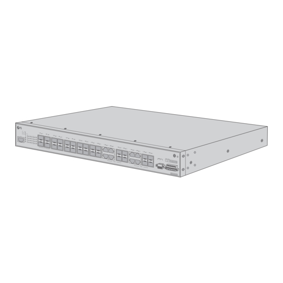
IES5100-24FS
L3 MANAGED INDUSTRIAL SWITCH
L3 MANAGED INDUSTRIAL SWITCH
SWITCH INDUSTRIEL MANAGEABLE L3
Quick Start Guide
Quick Start Anleitung
Guide de Démarrage Rapide
6
7
8
9
10
11
12
13
14
15
16
17
18
19
20
17
18
19
20
21
V1.0
22
23
24
21
22
23
24
PW R1/
PW R2
100 -24
0V
N L
PW R
L N AC
DC
Advertisement
Table of Contents

Related Manuals for FS IES5100-24FS


Summary of Contents for FS IES5100-24FS
- Page 1 12 16 20 24 13 17 PW R1/ PW R2 100 -24 PW R L N AC IES5100-24FS L3 MANAGED INDUSTRIAL SWITCH L3 MANAGED INDUSTRIAL SWITCH SWITCH INDUSTRIEL MANAGEABLE L3 Quick Start Guide V1.0 Quick Start Anleitung Guide de Démarrage Rapide...
- Page 2 Introduction Thank you for choosing IES5100-24FS L3 Managed Industrial Switch. This guide is designed to familiarize you with the layout of the switch and describes how to deploy it in your network. PWR2 PWR1/ PWR2 SFP+ PWR1 12 16 20 24...
-
Page 3: Hardware Overview
SFP+ PWR1/ PWR2 PWR1 12 16 20 24 100-240V L N AC 13 17 21 SFP+ COMBO COMBO IES5100-24FS Console SFP+ Combo Ports Description Console An RJ45 console port for serial management SFP+ SFP+ ports for 10G connection SFP port for 1G connection... -
Page 4: Front Panel
100-240V L N AC 13 17 21 SFP+ COMBO COMBO IES5100-24FS Power Alarm Output Power Input Installation Requirements Before the installation, make sure that you have the following: Screwdriver, static-proof wristband, bolt, Ethernet cable, other Ethernet terminal devices and control terminal. -
Page 5: Mounting The Switch
Mounting the Switch Desk Mounting IES5100-24TF PWR2 PWR1 CONSOLE PWR2 SFP+ PWR1 12 16 20 24 13 17 21 PWR1/ PWR2 SFP+ 100-240 V L N AC COMBO COMBO IES5 100- 24FS 1. Attach the four rubber pads to the four corners on the switch bottom. 2. -
Page 6: Grounding The Switch
PW R2 PW R1 SFP + 12 16 20 24 13 17 PW R1/ PW R2 100 -24 PW R L N AC 2. Attach the switch to the rack using the screws and tighten them. Grounding the Switch PW R1 / PW R2 10 0- 24 PW R... -
Page 7: Connecting The Console Port
Connecting the Console Port SY S PW R2 PW R1 SF P+ 12 16 CL I 20 24 13 17 1. Insert the RJ45 connector into the RJ45 console port on the front panel of the switch. 2. Connect the DB9 female connector of the console cable to the serial port on the PC. Connecting the SFP+ Ports SY S PW R2... - Page 8 Connecting the SFP Ports SY S PW R2 PW R1 SF P+ 12 16 CL I 20 24 13 17 PW R PWR2 SFP+ PWR1 12 16 20 24 PW R1 / PW R2 10 0- 24 PW R 13 17 21 L N AC SFP+ 1.
-
Page 9: Connecting The Power
10 0-2 40 PW R L N AC PWR1/ PWR2 100-240V L N AC IES5100-24FS Name Description Live line/Positive Null line/Negative Requiring good ground connection 2. Insert positive/negative AC/DC power wires into contacts 2 and 1 for PWR1 or 4 and 5 for PWR2,... - Page 10 PWR1 PWR2 Positive (+) Pin Negative (-) Pin Pin 2 / 4 Pin 1 / 5 NOTE: The wire gauge for the terminal block should be in the range of 12-24 AWG. Con guring the Switch Con guring the Switch Using the Console Port Step 1: Connect a computer to the console port of the switch with the console cable.
- Page 11 Quick Connect Protocol: Serial The port may be manually entered or selected from the list. Flow Control Port: COM3 DTR/DSR 115200 Baud rate: RTS/CTS Data bits: XON/XOFF Parity: None Stop bits: Name of pipe: Show quick connect on startup Save session Open in a tab Connect Cancel...
-
Page 12: Troubleshooting
Step 3: Open a browser, type http://192.168.1.1 and enter the default username and password, admin/admin. IE 8/9/10/11, Google Chrome, Firefox are supported admin Login Step 4: Click Login to display the web-based con guration page. Troubleshooting Faults Related To Power And Cooling System When the power switch is “ON”... -
Page 13: Online Resources
Contact Us Product Warranty FS ensures our customers that for any damage or faulty items due to our workmanship, we will o er a free return within 30 days from the day you receive your goods. This excludes any custom-made items or tailored solutions. - Page 14 Einführung Vielen Dank, dass Sie sich für den IES5100-24FS L3 Managed Industrial Switch entschieden haben. Diese Anleitung soll Sie mit dem Aufbau des Switches vertraut machen und beschreibt, wie Sie ihn in I hrem Netzwerk einsetzen. PWR2 PWR1/ PWR2 SFP+...
- Page 15 PWR2 SFP+ PWR1/ PWR2 PWR1 12 16 20 24 100-240V L N AC 13 17 21 SFP+ COMBO COMBO IES5100-24FS Console SFP+ Combo Port Beschreibung Console Ein RJ45-Console-Port für die serielle Verwaltung SFP+ SFP+-Ports für 10G-Verbindungen SFP-Port für 1G-Verbindung RJ45/SFP Combo...
-
Page 16: Montage Des Switches
12 16 20 24 100-240V L N AC 13 17 21 SFP+ COMBO COMBO IES5100-24FS Strom-Alarmausgang Stromeingang Installationsvoraussetzungen Vergewissern Sie sich vor der Installation, dass Sie Folgendes haben: Schraubendreher, statiksicheres Armband, Bolzen, Ethernet-Kabel, andere Ethernet-Endgeräte und Steuerterminal. Ein 19"-Rack in Standardgröße mit einer Mindesthöhe von 1 HE steht zur Verfügung. - Page 17 IES5100-24TF PWR2 SFP+ PWR1 12 16 20 24 13 17 21 PWR1/ PWR2 SFP+ 100-240 V L N AC COMBO COMBO IES5 100- 24FS PWR2 PWR1 CONSOLE 1. Befestigen Sie die vier Gummipads an den vier Ecken der Unterseite des Switches. 2.
- Page 18 PW R2 PW R1 SFP + 12 16 20 24 13 17 PW R1/ PW R2 100 -24 PW R L N AC 2. Befestigen Sie den Switch mit den Schrauben am Rack und ziehen Sie sie fest. Erdung des Switches PW R1 / PW R2 10 0- 24...
- Page 19 Anschließen des Console-Ports SY S PW R2 PW R1 SF P+ 12 16 CL I 20 24 13 17 1. Stecken Sie den RJ45-Stecker in den RJ45-Console-Port an der Vorderseite des Switches. 2. Verbinden Sie die DB9-Buchse des Console-Kabels mit dem seriellen Port des PCs. Anschließen der SFP+-Ports SY S PW R2...
- Page 20 Anschließen der SFP-Ports SY S PW R2 PW R1 SF P+ 12 16 CL I 20 24 13 17 PW R PW R1 / PW R2 PWR2 10 0- 24 SFP+ PW R PWR1 L N AC 12 16 20 24 13 17 21 SFP+ 1.
-
Page 21: Anschließen Der Stromversorgung
100-240V 10 0-2 40 PW R L N AC PWR1/ PWR2 100-240V L N AC IES5100-24FS Name Beschreibung Stromleiter/Positiv Nullleiter/Negative Erfordert eine gute Erdung 2. Stecken Sie die positiven/negativen AC/DC-Stromversorgungsdrähte in die Kontakte 2 und 1 für PWR1 oder 4 und 5 für PWR2 und lassen Sie dann die Taste los. - Page 22 PWR1 PWR2 Positiv (+) Pin Negativ (-) Pin Pin 2/4 Pin 1/5 HINWEIS: Die Drahtstärke für die Anschlussleiste sollte im Bereich von 12-24 AWG liegen. Kon gurieren des Switches Kon gurieren des Switches über den Console-Port Schritt 1: Schließen Sie einen Computer über das Console-Kabel an den Console-Port des Switches an. Schritt 2: Starten Sie die Terminalsimulationssoftware, z.
- Page 23 Quick Connect Protocol: Serial The port may be manually entered or selected from the list. Flow Control Port: COM3 DTR/DSR 115200 Baud rate: RTS/CTS Data bits: XON/XOFF Parity: None Stop bits: Name of pipe: Show quick connect on startup Save session Open in a tab Connect Cancel...
-
Page 24: Fehlersuche
Schritt 3: Ö nen Sie einen Browser, geben Sie http://192.168.1.1 ein und geben Sie den Standard- Benutzernamen und das Passwort admin/admin ein. IE 8/9/10/11, Google Chrome, Firefox are supported admin Login Schritt 4: Klicken Sie auf Login, um die webbasierte Kon gurationsseite anzuzeigen. Fehlersuche Fehler im Zusammenhang mit der Stromversorgung und dem Kühlsystem Wenn der Power Switch auf "ON"... - Page 25 Kontakt Produktgarantie FS garantiert seinen Kunden, dass wir bei Schäden oder fehlerhaften Artikeln, die auf unsere Verarbeitung zurückzuführen sind, eine kostenlose Rückgabe innerhalb von 30 Tagen nach Erhalt der Ware anbieten. Dies gilt nicht für Sonderanfertigungen oder maßgeschneiderte Lösungen.
- Page 26 Introduction Nous vous remercions d'avoir choisi le Switch Industriel Manageable L3 IES5100-24FS. Ce guide est conçu pour vous familiariser avec la con guration du switch et décrit comment procéder à son déploiement. PWR2 PWR1/ PWR2 SFP+ PWR1 12 16 20 24...
-
Page 27: Aperçu Du Matériel
SFP+ PWR1/ PWR2 PWR1 12 16 20 24 100-240V L N AC 13 17 21 SFP+ COMBO COMBO IES5100-24FS Console SFP+ Combo Ports Description Console Port console RJ45 pour la gestion en série SFP+ Ports SFP+ pour une connexion 10G... -
Page 28: Panneau Frontal
12 16 20 24 100-240V L N AC 13 17 21 SFP+ COMBO COMBO IES5100-24FS Alarme d'Alimentation Entrée d'Alimentation Exigences d'Installation Avant l'installation, assurez-vous que vous disposez des éléments suivants : Tournevis, bracelet antistatique, boulon, câble Ethernet, autres dispositifs terminaux Ethernet et terminal de contrôle. -
Page 29: Installation En Rack
Installation du Switch Installation sur Support IES5100-24TF PWR2 PWR1 PWR2 SFP+ PWR1 12 16 20 24 CONSOLE 13 17 21 PWR1/ PWR2 SFP+ 100-240 V L N AC COMBO COMBO IES5 100- 24FS 1. Fixez les quatre pads en caoutchouc aux quatre coins de la base du switch. 2. - Page 30 PW R2 PW R1 SFP + 12 16 20 24 13 17 PW R1/ PW R2 100 -24 PW R L N AC 2. Fixez le switch au rack à l'aide des vis et serrez-les. Mise à la Terre du Switch PW R1 / PW R2 10 0- 24...
- Page 31 Connexion du Port Console SY S PW R2 PW R1 SF P+ 12 16 CL I 20 24 13 17 1. Insérez le connecteur RJ45 dans le port de console RJ45 situé sur la face frontale du switch. 2. Connectez le connecteur femelle DB9 du câble de la console au port série du PC. Connexion des Ports SFP+ SY S PW R2...
- Page 32 Connexion des Ports SFP SY S PW R2 PW R1 SF P+ 12 16 CL I 20 24 13 17 PW R PW R1 / PW R2 PWR2 10 0- 24 SFP+ PWR1 PW R 12 16 20 24 L N AC 13 17 21 SFP+ 1.
-
Page 33: Connexion De L'alimentation
100-240V 10 0-2 40 PW R L N AC PWR1/ PWR2 100-240V L N AC IES5100-24FS N° Dénomination Description Ligne directe/Positif Ligne nulle/Négatif Requiert une bonne connexion à la terre 2. Insérez les ls d'alimentation AC/DC positifs/négatifs dans les contacts 2 et 1 pour PWR1 ou 4 et 5... - Page 34 PWR1 PWR2 Broche Positive (+) Broche Negative (-) Broche 2/4 Broche 1/5 NOTE : Le calibre du l pour le bornier doit être compris entre 12 et 24AWG. Con guration du Switch Con guration du Switch à l'Aide du Port Console Étape 1 : Connectez un ordinateur au port de console du switch à...
- Page 35 Quick Connect Protocol: Serial The port may be manually entered or selected from the list. Flow Control Port: COM3 DTR/DSR 115200 Baud rate: RTS/CTS Data bits: XON/XOFF Parity: None Stop bits: Name of pipe: Show quick connect on startup Save session Open in a tab Connect Cancel...
-
Page 36: Dépannage
Étape 3 : Ouvrez un navigateur, tapez http://192.168.1.1 et entrez le nom d'utilisateur et le mot de passe par défaut, admin/admin. IE 8/9/10/11, Google Chrome, Firefox are supported admin Login Étape 4 : Cliquez sur Login pour a cher la page de con guration basée sur le Web. Dépannage Défauts Liés au Système d'Alimentation et de Refroidissement Lorsque l'interrupteur d'alimentation est sur "ON", véri ez si le ventilateur fonctionne... -
Page 37: Garantie Du Produit
Garantie du Produit FS garantit à ses clients que tout article endommagé ou défectueux dû à sa fabrication pourra être retourné gratuitement dans un délai de 30 jours à compter de la date de réception de la marchandise. Ceci exclut les articles faits sur mesure ou les solutions personnalisées. -
Page 38: Compliance Information
EU konform ist. Eine Kopie der EU-Konformitätserklärung nden Sie unter www.fs.com/de/company/quality_control.html. FS.COM GmbH déclare par la présente que cet appareil est conforme à la Directive 2014/30/UE et 2014/35/UE. Une copie de la Déclaration UE de Conformité est disponible sur https://www.fs.com/fr/company/quality_control.html FS.COM LIMITED... - Page 39 UKCA Hereby, FS.COM Innovation Ltd declares that this device is in compliance with the Directive SI 2016 No. 1091 and SI 2016 No. 1101 CAN ICES-003(A)/NMB-003(A) English: This device contains licence-exempt transmitter(s)/receiver(s) that comply with Innovation, Science and Economic Development Canada’s licence-exempt RSS(s). Operation is subject to the following two conditions: (1) This device may not cause interference.
Need help?
Do you have a question about the IES5100-24FS and is the answer not in the manual?
Questions and answers