Advertisement
SPX Corporation
5885 11th Street
Rockford, IL 61109-3699 USA
Internet Address:
http://www.powerteam.com
Read and carefully follow these instructions before installation and use of this pump. Most problems with new
equipment are caused by improper operation and installation.
WARNING
● ●
All WARNING statements must be carefully observed to help prevent personal injury.
Hydraulic Hose
● ●
Before operating this tool, tighten all hose connections using the proper tools. Do not overtighten the
connections. Connections need only be tightened securely and leak-free. Overtightening may cause
premature thread failure or high pressure fittings to split at pressures lower than their rated capacities.
● ●
Should a hydraulic hose ever burst, rupture, or need to be disconnected, immediately shut off the pump.
Never attempt to grasp a leaking hose under pressure with your hands. The force of the escaping
hydraulic fluid could cause serious injury.
● ●
Do not subject the hose to potential hazard such as fire, extreme heat or cold, sharp surfaces, or heavy
impact. Do not allow the hose to kink, twist, curl or bend so tightly that the oil flow within the hose is
blocked or reduced. Periodically inspect the hose for signs of wear because any of these conditions can
damage the hose and may result in personal injury.
● ●
Do not use the hose to move attached equipment. Stress may damage the hose and cause personal injury.
● ●
Hose material and coupler seals must be compatible with the hydraulic fluid used. Hoses also must not
come in contact with corrosive materials such as creosote-impregnated objects and some paints. Consult
the manufacturer before painting a hose. Never paint the couplers. Hose deterioration due to corrosive
materials may result in personal injury.
Pump
● ●
Do not exceed the PSI hydraulic pressure rating noted on the pump nameplate or tamper with the internal
high pressure relief valve. Creating pressure beyond rated capacities may result in personal injury.
● ●
Before replenishing the oil level, retract the system to prevent overfilling the pump reservoir. An overfill
may cause personal injury due to excess reservoir pressure created when cylinders are retracted.
Cylinder
● ●
Do not exceed rated capacities of the cylinders. Excess pressure may result in personal injury.
● ●
Do not set poorly-balanced or off-center loads on a cylinder. The load may tip and cause personal injury.
Power Supply (Gasoline Engine)
● ●
Read the instruction manual for the gasoline engine before using.
● ●
Do not allow fuel to splash on the engine when refueling.
● ●
Do not add fuel when the engine is running or very hot.
Note: Removed all references to models PG1204S and
PG1204S-CCL at the last revision(s) made to this form.
© SPX Corporation
®
Tech. Services: (800) 477-8326
Fax: (800) 765-8326
Order Entry: (800) 541-1418
Fax: (800) 288-7031
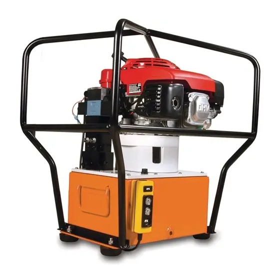
MODEL B
GAS HYDRAULIC PUMP
SAFETY PRECAUTIONS
Form No. 102652
Operating Instructions for:
PG1203
PG1204
PG1204-ITE
PG1204-LEAD
Sheet No.
Rev. 2
PG1204-LRC
PG1204-MC
PG1204-PRO
PG1204-SEW
PG1204S- ATLAS
1 of 8
Date: 1 Apr. 1997
Advertisement
Table of Contents

Subscribe to Our Youtube Channel
Related Manuals for SPX POWER TEAM PG1203


Summary of Contents for SPX POWER TEAM PG1203
- Page 1 Form No. 102652 ® Operating Instructions for: SPX Corporation Tech. Services: (800) 477-8326 PG1204-LRC 5885 11th Street Fax: (800) 765-8326 Rockford, IL 61109-3699 USA Order Entry: (800) 541-1418 PG1203 PG1204-MC Fax: (800) 288-7031 PG1204 PG1204-PRO Internet Address: PG1204-ITE PG1204-SEW http://www.powerteam.com PG1204-LEAD...
-
Page 2: Pump Operation
Parts List and Operating Instructions, Form No. 102652, Back sheet 1 of 8 SET-UP Motor Hook-up and Operation Refer to the instruction manual for the gasoline engine. Hydraulic Connections 1. Clean all areas around the oil ports of the pump and cylinders. 2. - Page 3 Parts List and Operating Instructions Form No. 102652 Valve Operation 3-Way Manual Valve Neutral (Hold): Pressure to tank - cylinder port blocked. Advance: Pressure to cylinder port "A." Return: Pressure and cylinder port to tank. Pressure holds without loss when shifted from cylinder port to "hold"...
-
Page 4: Hydraulic Schematics
150/200 PSI PG1204-LEAD, PG1204-LRC 500/200 PSI PG1204-MG1204-PRO, For: & PG1204-SEW PG1204- ITE, PG1204-LEAD, PG1204-MC, To Customer Connections & PG1204-PRO High Pressure Relief Valve 540/780 PSI 10,100/10,700 PSI For: PG1203, PG1204, PG1204-LRC, & PG1204-SEW 950/1200 PSI For: PG1204S-ATLAS Valve Connections PG1204S-ATLAS... -
Page 5: Preventive Maintenance
Parts List and Operating Instructions Form No. 102652 PREVENTIVE MAINTENANCE NOTE: Any repairs of servicing that requires dismantling the pump must be performed in a dirt-free environment by a qualified technician. Bleeding Air from the System Upon initial startup or after prolonged use, a significant amount of air may accumulate within the hydraulic system. This entrapped air can cause the cylinder to respond slowly or behave in an unstable manner. -
Page 6: Troubleshooting Guide
Parts List and Operating Instructions, Form No. 102652, Back sheet 3 of 8 TROUBLESHOOTING GUIDE WARNING: ● ● To help prevent personal injury, any repair work or troubleshooting must be done by qualified personnel familiar with this equipment. ● ● Use the proper gauges and equipment when troubleshooting. - Page 7 Parts List and Operating Instructions Form No. 102652 PROBLEM CAUSE SOLUTION Pump builds pressure but cannot 1. Check to see if there are any 1. Seal leaking pipe fittings with maintain pressure. external leaks. If no oil leakage pipe sealant. is visible, the problem is internal.
- Page 8 Parts List and Operating Instructions, Form No. 102652, Back sheet 4 of 8 PROBLEM CAUSE SOLUTION Cylinder(s) will not retract. 1. Check the system pressure; if 1. Check the cylinders for broken the pressure is zero, the control return springs, and check valve is releasing pressure and couplers to ensure that they are the problem may be in the...
- Page 9 Parts List and Operating Instructions Form No. 102652 PARTS LIST SIDE VIEW 15, 16 Basic Pump Ass'y See sheet 6 of 8 .010 .040 (DISTANCE BETWEEN BOTTOM OF SHAFT EXTENSION #420052 AND BOTTOM OF SLOT IN COUPLING #251206) Sheet No. 5 of 8 Rev.
- Page 10 Parts List and Operating Instructions, Form No. 102652, Back sheet 5 of 8 Item Part Req'd Description 9520 Valve Assembly (3 pos./3-way; For PG1203; See Form No.'s 101377 & 102527) 9506 Valve Assembly (3 pos./4-way; For PG1204, PG1204-ITE, PG1204-LRC, & PG1204-SEW; See Form No.'s 100628 & 102527)
-
Page 11: General Pump Assembly
Parts List and Operating Instructions Form No. 102652 GENERAL PUMP ASSEMBLY 10 11 12 Basic Pump Assembly 19, 20 See sheet 7 of 8 31, 32 Sheet No. 6 of 8 Rev. 2 Date: 1 Apr. 1997... - Page 12 Parts List and Operating Instructions, Form No. 102652, Back sheet 6 of 8 Item Part Req'd Description 10177 Machine Screw (1/4-20 UNC x 3/4 Lg.) 11173 Fitting 20771 Poppet 10266 O-ring (3/8 x 1/4 x 1/16) 10015 Soc. Hd. Cap Screw (1/4-28 UNF x 1"...
-
Page 13: Basic Pump Assembly
Parts List and Operating Instructions Form No. 102652 BASIC PUMP ASSEMBLY Sheet No. 7 of 8 Rev. 2 Date: 1 Apr. 1997... - Page 14 Parts List and Operating Instructions, Form No. 102652, Back sheet 7 of 8 Item Part Req'd Description 10020 Soc. Hd. Cap Screw (1/4-20 UNC x 1-1/4 Lg; Torque to 170/180 in. lbs.) 33114 High Pressure Pump Assembly (See sheet 8 of 8) 10361 Compression Spring (1/4 O.D.
-
Page 15: High Pressure Pump Assembly
Parts List and Operating Instructions Form No. 102652 HIGH PRESSURE PUMP ASSEMBLY See diagram on reverse side for inportant assembly information. Sheet No. 8 of 8 Rev. 2 Date: 1 Apr. 1997... -
Page 16: Bolt Tightening Sequence
Parts List and Operating Instructions, Form No. 102652, Back sheet 8 of 8 33114 PUMP ASSEMBLY 6 pistons -- 9/32 dia. Item Part Req'd Description 10442 Copper Washer (3/8 x 1/4 x 1/32) 10002 Soc. Hd. Cap Screw (1/4-20 UNC x 3/8 Lg.; Torque to 140/160 in.
Need help?
Do you have a question about the PG1203 and is the answer not in the manual?
Questions and answers