Table of Contents
Advertisement
Quick Links
®
SPX Hydraulic Technologies
5885 11th Street
Rockford, IL 61109-3699 USA
Tech. Services: (800) 477-8326
Fax: (800) 765-8326
Order Entry: (800) 541-1418
Fax: (800) 288-7031
powerteam.com
Read and carefully follow these instructions. Most problems with new equipment are caused by improper operation or
installation.
WARNING:
To help prevent personal injury,
HYDRAULIC HOSE
Before operating the pump, tighten all hose connections with the proper tools. Do not overtighten.
Connections should only be secure and leak-free. Overtightening can cause premature thread failure or
G
high pressure fittings to split at pressures lower than their rated capacities.
Should a hydraulic hose ever rupture, burst, or need to be disconnected, immediately shut off the pump
and shift the control valve twice to release all pressure. Never attempt to grasp a leaking pressurized
G
hose with your hands. The force of escaping hydraulic fluid could cause serious injury.
Do not subject the hose to potential hazard such as fire, sharp surfaces, extreme heat or cold, or heavy
impact. Do not allow the hose to kink, twist, curl, or bend so tightly that the oil flow within the hose is
G
blocked or reduced. Periodically inspect the hose for wear, because any of these conditions can damage
the hose and result in personal injury.
Do not use the hose to move attached equipment. Stress can damage the hose and cause personal injury.
G
Hose material and coupler seals must be compatible with the hydraulic fluid used. Hoses also must not
come in contact with corrosive materials such as creosote-impregnated objects and some paints.
G
Consult the manufacturer before painting a hose. Never paint the couplers. Hose deterioration due to
corrosive materials can result in personal injury.
PUMP
Do not exceed the PSI rating noted on the pump nameplate or tamper with the internal high pressure
relief valve. Creating pressure beyond rated capacities can result in personal injury.
G
Before adding oil, retract the system to prevent overfilling the pump reservoir. An overfill can cause
personal injury due to excess reservoir pressure created with cylinders are retracted.
G
CYLINDER
Do not exceed the rated capacities of the cylinders. Excess pressure can result in personal injury.
G
Do not set poorly-balanced or off-center loads on a cylinder. The load can tip and cause personal injury.
G
POWER SUPPLY
All electrical work must be done by a qualified electrician.
G
Disconnect the power supply before removing the electrical box cover or performing repairs and
maintenance.
G
Never use an ungrounded (two-prong) extension cord with this unit.
G
© SPX Corporation
SPX Corporation
®
655 Eisenhower Drive
Owatonna, MN 55060-0995 USA
Phone: (507) 455-7000
Tech. Services: (800) 533-6127
Fax: (800) 955-8329
Order Entry: (507) 455-1480
Fax: (800) 283-8665
International Sales: (507) 455-7223
Fax: (507) 455-7746
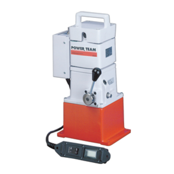
MODEL C & D
HIGH SPEED
HYDRAULIC PUMP
SAFETY PRECAUTIONS
Form No. 102355
Operating Instructions for:
2P-5500
4033
2P-5550
4035
4030
4036
4031
4037
4032
89300-00
Sheet No.
Rev. 2
Date: 24 August 2009
201905
D-01023-AA
D-01026-AA
PE18 Series
Y27 Series
1 of 4
Advertisement
Table of Contents

Related Manuals for SPX POWER TEAM PE18 Series


Summary of Contents for SPX POWER TEAM PE18 Series
- Page 1 Order Entry: (800) 541-1418 4030 4036 D-01026-AA Order Entry: (507) 455-1480 Fax: (800) 288-7031 Fax: (800) 283-8665 4031 4037 PE18 Series International Sales: (507) 455-7223 powerteam.com 4032 89300-00 Y27 Series Fax: (507) 455-7746 MODEL C & D HIGH SPEED HYDRAULIC PUMP Read and carefully follow these instructions.
-
Page 2: Hose Connections
Operating Instructions, Form No. 102355, Back sheet 1 of 4 SET-UP Hose Connections 1. Clean all areas around the oil ports of the pump and cylinder. 2. Inspect all threads and fittings for signs of wear and damage. Replace as needed. Clean all hose ends, couplers, or union ends. -
Page 3: Preventive Maintenance
Operating Instructions Form No. 102355 Three-Way Valve (use with single-acting cylinders) 1. Place the valve handle in the neutral position as shown in Figure 4. 2. Jog the motor toggle switch several times. Place the switch on RUN, and let the pump idle for a few minutes. 3. -
Page 4: Bleeding Air From The System
Operating Instructions, Form No. 102355, Back sheet 2 of 4 Bleeding Air From The System Air can accumulate in the hydraulic system during the initial set-up or after prolonged use causing the cylinder to respond slowly or in an unstable manner. To remove the air: 1. -
Page 5: Optional Accessories
Operating Instructions Form No. 102355 OPTIONAL ACCESSORIES Pressure Regulating Controls The pressure range for this pump is from 1000 PSI to 10,000 PSI. A pressure regulating valve can be adjusted to bypass oil at a certain pressure setting while the pump continues to run. A pressure switch can be adjusted to stop the pump motor at a certain pressure setting. -
Page 6: Troubleshooting Guide
Operating Instructions, Form No. 102355, Back sheet 3 of 4 TROUBLE-SHOOTING GUIDE WARNING: To help prevent personal injury, North American & International Color Codes Trouble-shooting and repair work must be done by Conductors North American International qualified technicians who are familiar with this equipment. -
Page 7: Operating Instructions
Operating Instructions Form No. 102355 PROBLEM CAUSE SOLUTION Pump is not delivering oil (cont'd) 10. Relief valve or low pressure 10. Adjust as needed. unloading valve set wrong. 11. Motor rotating wrong direction. 11. Looking at motor shaft end, motor must rotate clockwise. Reverse lead wires to brush holders, if necessary. - Page 8 Operating Instructions, Form No. 102355, Back sheet 4 of 4 PROBLEM CAUSE SOLUTION Pump does not build full pressure (cont'd) 9. Internal leakage. 9. Look for leaks around entire inner mechanism. If there are no visible leaks, the low-to-high pressure ball check may be leaking.
Need help?
Do you have a question about the PE18 Series and is the answer not in the manual?
Questions and answers