Table of Contents
Advertisement
Quick Links
SPX Corporation
5885 11th Street
Rockford, IL 61109-3699 USA
Internet Address:
http://www.powerteam.com
21
20
19
18
17
16
15
Basic Pump
Assembly
See sheet
3 of 7
14
© SPX Corporation
®
Tech. Services: (800) 477-8326
Fax: (800) 765-8326
Order Entry: (800) 541-1418
Fax: (800) 288-7031
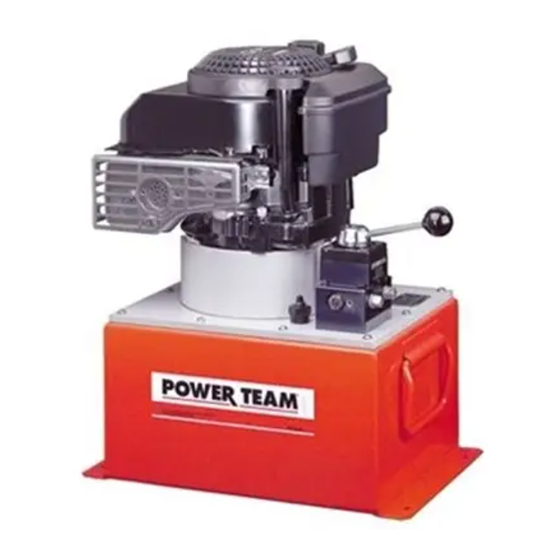
MODEL C
GAS DRIVEN
HYDRAULIC PUMP
SIDE VIEW
13
Form No. 102805
Parts List and
Operating Instructions for:
1, 2, 3
4
12
Sheet No.
Rev. 10
PG554-AMKUS
5
6
7
23
8
10,
22
11
1 of 7
Date: 18 July 2000
Advertisement
Table of Contents

Related Manuals for SPX POWER TEAM PG554-AMKUS


Summary of Contents for SPX POWER TEAM PG554-AMKUS
- Page 1 Operating Instructions for: SPX Corporation Tech. Services: (800) 477-8326 5885 11th Street Fax: (800) 765-8326 Rockford, IL 61109-3699 USA Order Entry: (800) 541-1418 Fax: (800) 288-7031 PG554-AMKUS Internet Address: http://www.powerteam.com MODEL C GAS DRIVEN HYDRAULIC PUMP SIDE VIEW 1, 2, 3...
- Page 2 Parts List and Operating Instructions, Form No. 102805, Back sheet 1 of 7 Item Part Req'd Description 26804 Stud 250243 Stud (Located on opposite side of engine.) 10246 Washer (For 5/16 bolt) 13116 Locknut (5/16-18 UNC; Note: This nut should fully engage threads of studs [Item #1].) 58354BK2 Mount Plate 9500...
- Page 3 Parts List and Operating Instructions Form No. 102805 TOP VIEW AND SECTION B-B 3, 4 "B" "B" Fill counterbore with sealant where mounting plate #58051 overlaps. Sheet No. 2 of 7 Section B-B Rev. 10 Date: 18 July 2000...
-
Page 4: Hydraulic Schematic
Parts List and Operating Instructions, Form No. 102805, Back sheet 2 of 7 Item Part Req'd Description 58207 Cover Plate 10177 Screw (1/4-20 X 3/4 Lg.; Apply Loctite #242 and torque to 90/100 in. lbs.) 252642 Breather/Filler Cap 200415 O-ring (13/16 X 5/8 X 3/32) 10575 Drive Screw... -
Page 5: Basic Pump Assembly
Parts List and Operating Instructions Form No. 102805 BASIC PUMP ASSEMBLY High Pressure Pump Assembly #33113 See sheet 4 of 7. 31, 32 .065 .075 .265 .275 Sheet No. 3 of 7 Rev. 10 Date: 18 July 2000... - Page 6 Parts List and Operating Instructions, Form No. 102805, Back sheet 3 of 7 Item Part Item Part Req'd Description Req'd Description 10020 Cap Screw 10001 Cap Screw (1/4-20 UNC X 1-1/2 Lg.; (1/4-20 UNC X 3/8 Lg.; Torque to 170/180 in. lbs.) Torque to 50/60 in.
-
Page 7: High Pressure Pump Assembly
Parts List and Operating Instructions Form No. 102805 HIGH PRESSURE PUMP ASSEMBLY Sheet No. 4 of 7 Rev. 10 Date: 18 July 2000... -
Page 8: Bolt Tightening Sequence
Parts List and Operating Instructions, Form No. 102805, Back sheet 4 of 7 Item Part Req'd Description 10442 Copper Washer (3/8 x 1/4 x 1/32) 10002 Soc. Hd. Cap Screw (1/4-20 UNC x 3/8 Lg.: Torque to 140/160 in. lbs.) *24549 Valve Guide *10445... -
Page 9: Safety Precautions
Parts List and Operating Instructions Form No. 102805 NOTE: • Carefully inspect the pump upon arrival. The carrier, not the manufacturer, is responsible for any damage resulting from shipment. • Read and carefully follow these instructions. Most problems with new equipment are caused by improper operation or installation. -
Page 10: Pump Operation
Parts List and Operating Instructions, Form No. 102805, Back sheet 5 of 7 Reservoir Venting Before using the pump, remove the plastic shipping plug from the reservoir fill hole and replace with the breather cap provided. PUMP OPERATION Priming the Pump When operating the pump for the first time: 1. -
Page 11: Troubleshooting Guide
Parts List and Operating Instructions Form No. 102805 Draining and Cleaning the Reservoir IMPORTANT: Clean the pump exterior before the pump interior is removed from the reservoir. 1. Remove the screws that fasten the pump assembly to the reservoir. Remove the pump assembly from the reservoir. - Page 12 Parts List and Operating Instructions, Form No. 102805, Back sheet 6 of 7 PROBLEM CAUSE SOLUTION Pump is not delivering oil or delivers 6. Oil is bypassing through a 6. By removing the cylinder and only enough oil to advance double-acting cylinder.
- Page 13 Parts List and Operating Instructions Form No. 102805 PROBLEM CAUSE SOLUTION Cylinder(s) will not retract. 1. Check the system pressure; if 1. Check the cylinders for broken the pressure is zero, the control return springs, and check valve is releasing pressure and couplers to ensure that they are the problem may be in the completely coupled.
Need help?
Do you have a question about the PG554-AMKUS and is the answer not in the manual?
Questions and answers
2 или 4х тактный двигатель