
Related Manuals for Piazzetta IP 11


Summary of Contents for Piazzetta IP 11
- Page 1 The instruction manual is an integral part of the product Pellet inserts IP 11 PRODUCT INFORMATION, INSTALLATION AND MAINTENANCE...
- Page 2 TRONIC FORMAT on our company website (www.piazzetta.com), under “Products”, on the specific product characteristics page. This document is the property of Gruppo Piazzetta S.p.A. and no part of it may be reproduced or disclosed to third parties, whol- ly or in part, without written permission All rights reserved by Gruppo Piazzetta S.p.A..
-
Page 3: Table Of Contents
PRODUCT INFORMATION, INSTALLATION AND MAINTENANCE CONTENTS GENERAL INFORMATION PRODUCT INFORMATION Product description Part identification Safety devices Check devices Product identification data Characteristics Accessories upon request Technical data Sizes FUEL Pellet specifications Information regarding pellet loading GENERAL INFORMATION REGARDING THE SYSTEM Installation room Fresh air intake Chimney... -
Page 4: General Information
(authorized technical assistance centre). in the sections " FAULTS " or " MESSAGES - - Gruppo Piazzetta S.p.A. cannot be held liable for situations of SAFETY WARNINGS - ANOMALIES ". risk, defects, damage, product malfunctioning or for damage... - Page 5 PRODUCT INFORMATION, INSTALLATION AND MAINTENANCE Product use may cause some surfaces to During the operation and/or cooling phase, become extremely hot (the glass, the exter- slight creaking noises may be heard. This nal surfaces, the handles, the smoke outlet is not considered a defect, but is a conse- passage).
-
Page 6: Product Information
PRODUCT INFORMATION, INSTALLATION AND MAINTENANCE PRODUCT INFORMATION Do not use the appliance as an incinerator or in any way other than that for which it was designed. PRODUCT DESCRIPTION Do not use the appliance if the glass or seals ■ on the door are damaged. -
Page 7: Part Identification
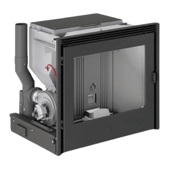
PRODUCT INFORMATION, INSTALLATION AND MAINTENANCE PART IDENTIFICATION Hot air outlet Combustion chamber Door Ceramic glass Door handle Grate deflector Pellet delivery hole Grate Electronic control unit 10 Electrical power cable 11 Safety thermostat 12 Pressure switch 13 Metal structure 14 Pellet hopper cover 15 Control panel 16 Pellet hopper 17 Pellet sensor... -
Page 8: Safety Devices
PRODUCT INFORMATION, INSTALLATION AND MAINTENANCE Electronic control unit: SAFETY DEVICES the electronic control unit signals and controls a series of events including power and ignition failure. The appliance is equipped with the following safety and check devices which stop the stove from operating if any faults occur. If any safety warnings or alarms are activated, please consult the “... -
Page 9: Product Identification Data
PRODUCT INFORMATION, INSTALLATION AND MAINTENANCE PRODUCT IDENTIFICATION DATA CHARACTERISTICS Each product is identified in the following way: Structure: - IDENTIFICATION DATA PLATE (1) with the model (A) and ap- - in steel pliance performance specifications Firebox: - SERIAL NUMBER PLATE (2) with the serial number of the ap- - in steel pliance (B) - in cast iron... -
Page 10: Technical Data
PRODUCT INFORMATION, INSTALLATION AND MAINTENANCE TECHNICAL DATA Model IP 11 Type YP115-01 Unit of meas- at nominal at part load Description urement heat output heat output Fuel natural pure wood pellets Heat Output Hourly fuel consumption kg/h 1,09 Efficiency 87,3... -
Page 11: Sizes
PRODUCT INFORMATION, INSTALLATION AND MAINTENANCE (values in cm) SIZES IP 11 Fig. 5 32,5 8 cm 6 cm A Smoke outlet Combustion air duct IP 11 with PELLET DRAWER KIT Fig. 6 32,5 8 cm 6 cm A Smoke outlet Combustion air duct DT2005426_H072574EN0_00... - Page 12 IP 11 with SUPPORT KIT Fig. 7 32,5 4 ÷ 14 8 cm 6 cm A Smoke outlet Combustion air duct IP 11 with PELLET LOADING KIT Fig. 8 24,5 Ø 32,5 8 cm 6 cm A Smoke outlet Combustion air duct...
- Page 13 PRODUCT INFORMATION, INSTALLATION AND MAINTENANCE IP 11 with ADDITIONAL PELLET HOPPER KIT Fig. 9 23,2 0÷ 26,5 102,1 32,5 39,5 8 cm 6 cm A Smoke outlet Combustion air duct DT2005426_H072574EN0_00...
-
Page 14: Fuel
Only keep the cover of the pellet hopper open for as ■ thorised by Gruppo Piazzetta S.p.A.. long as it takes to complete the refill operation. To en- Using pellets that are out of date or not in conformity ■... -
Page 15: General Information Regarding The System
PRODUCT INFORMATION, INSTALLATION AND MAINTENANCE GENERAL INFORMATION Do not install type A and B gas appliances in rooms REGARDING THE SYSTEM where there are also heat generators powered by wood (or solid fuels in general) or in adjoining rooms (in line Below is some general information regarding the system, appli- with UNI standards). -
Page 16: Fresh Air Intake
PRODUCT INFORMATION, INSTALLATION AND MAINTENANCE The connecting pipe for the combustion air inlet of the appliance must comply with the following requirements: The existence of more than one appliance is only per- - have a diameter equal to or greater than the diameter of the mitted if allowed by the regulations and manufacturer inlet on the appliance of each individual appliance. -
Page 17: Chimney Terminal
PRODUCT INFORMATION, INSTALLATION AND MAINTENANCE - must be constructed in such a way as to ensure that in the event of winds from all directions and angle, discharge of the combustion products is assured (chimney terminal with anti downdraught cowl) - must be positioned outside the reflux area - must be positioned taking into account the roof inclination and respect the distances in relation to buildings, plants, aerials or... - Page 18 PRODUCT INFORMATION, INSTALLATION AND MAINTENANCE In particular, remember that the connecting flue pipe: Some systems – particularly those with appliances equipped with - must be in compliance with regulations, equipped with CE a boiler – may cause condensation to form, even if you abide by marking and be made respecting all safety requirements the indications provided.
- Page 19 PRODUCT INFORMATION, INSTALLATION AND MAINTENANCE Fig. 14 Fig. 15 DT2005426_H072574EN0_00...
-
Page 20: Preparations For Installation
PRODUCT INFORMATION, INSTALLATION AND MAINTENANCE After having removed the material protecting the appliance, re- PREPARATIONS FOR INSTALLATION move all the retainers securing the appliance to the pallet and then remove it from the pallet. Proceed as follows: Product installation and maintenance must be carried - position the protections (1 and 2) present in the package in out exclusively by qualified personnel with sufficient front of the pallet to protect the floor... -
Page 21: Installation
PRODUCT INFORMATION, INSTALLATION AND MAINTENANCE - remove the product fully to unscrew the two front screws (4) INSTALLATION For all installation and maintenance interventions which require access to inside the cladding, the smoke chamber or access to electrical and electronic parts, the user must contact a T.A.C. -
Page 22: Installation Kit And Accessories
PRODUCT INFORMATION, INSTALLATION AND MAINTENANCE Please refer to the section " TECHNICAL DATA " and in- Distance (F): for information regarding the safety dis- stallation instructions for the values. tances, installation methods, maintenance, safety and insulation, please refer to the indications attached pro- vided by the connecting flue pipe manufacturer. -
Page 23: Control Panel
PRODUCT INFORMATION, INSTALLATION AND MAINTENANCE CONTROL PANEL To ensure that the room temperature is read correctly and the appliance functions as it should, you must take note of the information provided below. The control panel is not installed on the appliance. The control panel should be installed separately using the cable supplied as standard. -
Page 24: Optional Support
PRODUCT INFORMATION, INSTALLATION AND MAINTENANCE - position the base in the installation housing, observing the po- OPTIONAL SUPPORT sition measurements in relation to the extractable part of the product Position the support at the established point taking into account - check that the base is level and insert suitable shims where re- its position in relation to the stove and fix it to the flooring using quired the holes (1) present on the support feet. -
Page 25: Extractable Part
PRODUCT INFORMATION, INSTALLATION AND MAINTENANCE EXTRACTABLE PART Proceed as follows: - COMPLETELY extract the sliding rails present on the base - insert the bracket (1) between the outside guide (2) and the support guide (3) Fig. 30 Fig. 28 - fix the bracket using the screws (4) Fig. -
Page 26: Connection To The Smoke Outlet
The electrical cables MUST NOT come into contact with hot or moving parts. Additional requirements for the connecting flue pipe Gruppo Piazzetta S.p.A. supplies pipes and bends for the connect- ing flue pipe, all of which are approved and specifically sized for 6.8.1 Power cable the smoke outlet of its products. - Page 27 PRODUCT INFORMATION, INSTALLATION AND MAINTENANCE The appliance must be connected to a 230 V 50 Hz socket via a 6.8.4 Control panel supply cable(A) with a suitable diameter (not supplied). For installation: For installation: - the appliance must not be connected to the electrical power - connect the power cable to the end of the cable (A).
-
Page 28: Start-Up And Operating Test
General information mally open). Do not connect any live elements. With the installation of cladding already designed by Gruppo Piazzetta S.p.A., it is also necessary to refer to Use a 2x0.5 mm cable to make the connection. the installation manual of the cladding itself. - Page 29 PRODUCT INFORMATION, INSTALLATION AND MAINTENANCE Failure to respect the indications provided may com- promise the correct air flow and consequently, the safe- ty of the product. The convective air outlets must not be confused with the fresh air intake. The convective air outlets serve to disperse the heat ■...
- Page 30 PRODUCT INFORMATION, INSTALLATION AND MAINTENANCE Example A Fig. 37 40 min 20 D 79,5 G dx Position in relation to the cladding 79,5 Sizes in cm Minimum side space, with product extracted, to enable installa- H Upper ventilation vents (convective air outlet) tion, disassembly Rear ventilation vents (convective air inlet) Minimum side space, with product extracted, to enable access...
-
Page 31: Ventilation Vents
PRODUCT INFORMATION, INSTALLATION AND MAINTENANCE VENTILATION VENTS Please refer to and carefully read the section " MINI- Hot air comes out through the natural convection system of the MUM SAFETY DISTANCES ". ventilation vents positioned at the top of the supporting wall or the hood. -
Page 32: Loading Pellets With Optional Drawer Kit
PRODUCT INFORMATION, INSTALLATION AND MAINTENANCE To replace the product, CAREFULLY push the extracted part until LOADING PELLETS WITH OPTIONAL you hear a "click" sound which indicates that the safety elements DRAWER KIT is back in place. - close the door. Where the pellet drawer kit is installed, pellet loading can be car- ried out from the front part using the relevant extractable drawer in the upper part. -
Page 33: Scheduled Maintenance
PRODUCT INFORMATION, INSTALLATION AND MAINTENANCE Maintenance interventions are mandatory in order to ensure Recommended interval safety, for correct and efficient stove operation and to guarantee Interventions which may be carried out by the user a long life of operation. If maintenance is not carried out with the recommended frequency, appliance performance could suffer Glass 1 day... -
Page 34: Cleaning The Painted Metal Parts
PRODUCT INFORMATION, INSTALLATION AND MAINTENANCE 10.3 CLEANING THE PAINTED METAL PARTS The glass should be cleaned when cold using ammo- When cleaning the painted metal parts, use a soft cloth mois- nia-based non-corrosive degreasing agents (for exam- tened with water. ple, do not use solvents). -
Page 35: Cleaning The Combustion Chamber
PRODUCT INFORMATION, INSTALLATION AND MAINTENANCE - remove part (4) Fig. 44 Fig. 46 - remove all the residue formed on the side walls and at the top Before turning on the appliance, check that the grate is of the firebox positioned correctly in its seat (and pushed towards the - clean the hole and the grate (5) without removing it start-up hole). -
Page 36: Cleaning The Room Fan
PRODUCT INFORMATION, INSTALLATION AND MAINTENANCE Recommended cleaning frequency: refer to the section " SCHEDULED MAINTENANCE ". The appliance must be cleaned with the fire out, the appliance completely cold and with the power cable disconnected. Cleaning must only be carried out by a T.A.C. (Technical ■... -
Page 37: When Not In Use
PRODUCT INFORMATION, INSTALLATION AND MAINTENANCE FUSE ON THE SMOKE INTAKE / EXTRACTOR FAN Proceed as follows: After a period of inactivity, the problem of expansion of - open the fuse box drawer (1) in the power cable of the smoke the materials and emission of vapours could recur Refer intake/extractor fan to the section "... -
Page 38: Reference Standards
PRODUCT INFORMATION, INSTALLATION AND MAINTENANCE 13 REFERENCE STANDARDS Country of application: The European Union EN 14785 Residential space heating appliances fired by wood pellets - Requirements and test methods EN 60335-1 Household and similar electrical appliances. Safety - Part 1: General requirements EN 60335-2-102 Household and similar electrical appliances. -
Page 39: Appendix
PRODUCT INFORMATION, INSTALLATION AND MAINTENANCE 14 APPENDIX Identification data plate: key Please read and comply with the instructions for installation, use and maintenance. Model = Model Type = Type DoP = Declaration of performance N.Body = Notified laboratory Pn = Nominal heat output Pp = Part load heat output Pnom = Nominal space heat output Ppart = Part load space heat output... - Page 40 Via Montello, 22 31011 Asolo (TV) - ITALY Tel. +39.04235271 - Fax +39.042355178 www.piazzetta.com e-mail:infopiazzetta@piazzetta.it...
Need help?
Do you have a question about the IP 11 and is the answer not in the manual?
Questions and answers