Table of Contents
Advertisement
Quick Links
Advertisement
Table of Contents

Related Manuals for Testboy TV 456


Summary of Contents for Testboy TV 456
- Page 1 ® Testboy TV 456 User manual Version 1.2...
-
Page 2: Table Of Contents
3.4.1 Terminal voltage monitoring 3.4.2 Battery indicator 3.4.3 Field for messages 3.4.4 Audible warnings 3.4.5 Help screens Equipment set and accessories 3.5.1 Standard equipment TESTBOY TV 456 3.5.2 Optional accessories Operation of the instrument Function selection Settings Measurements Insulation resistance Continuity test 5.2.1 R Low Test... - Page 3 TESTBOY TV 456 Maintenance Replacing fuses Cleaning Regular calibration Warranty and repair Technical data Replacing the fuse Contact resistance 7.2.1 Niederohm 7.2.2 Low-current passage RCD test 7.3.1 General data 7.3.2 Contact voltage 7.3.3 Release time 7.3.4 Tripping current Fault loop impedance and fault current...
-
Page 4: Foreword
Foreword 1 Foreword Congratulations on your decision to purchase the TESTBOY instrument with accessories from TESTBOY. The instrument has been developed based on extensive experience gained over many years of dealing with test equipment for electrical installations. The TESTBOY instrument is intended as a professional, multifunctional, portable test instrument for carrying out all measurements for the comprehensive inspection of electrical installations in buildings. -
Page 5: Safety And Operating Instructions
2.1 Warnings and notes To achieve the highest level of operator safety when performing various tests and measurements, Testboy recommends that you keep your TESTBOY instrument in good condition and undamaged. When using the instrument, the following general warnings must be observed: The symbol on the instrument means "Read the manual very carefully". - Page 6 TESTBOY TV 456 Warnings and notes Warnings regarding the measurement functions: Insulation resistance The insulation resistance measurement may only be carried out on de-energised ❑ objects! Do not touch the DUT during measurement or before it is completely discharged! ❑...
- Page 7 TESTBOY TV 456 Warnings and notes RCD functions The parameters set for one function are also retained for other RCD functions. ❑ The measurement of the contact voltage does not normally trip the residual ❑ current device. However, the tripping limit of the RCD may be exceeded as a result of leakage currents flowing to the PE protective conductor or via the capacitive connection between the L and PE conductors.
-
Page 8: Battery And Charging
Remove all batteries from the battery compartment if the instrument will not be ❑ used for a long period of time. Alkaline or rechargeable NiCd or NiMH batteries of size AA can be used. Testboy ❑ only recommends the use of rechargeable batteries with 2300 mAh or more. - Page 9 TESTBOY TV 456 Battery and charging Notes: The charger in the instrument is a so-called cell pack charger. This means that ❑ the battery cells are connected in series during charging. The battery cells must be equivalent (same state of charge and type, same age).
-
Page 10: Applied Standards
TESTBOY TV 456 Applied standards 2.3 Applied standards TESTBOY instruments are manufactured and tested in accordance with the following regulations: Electromagnetic compatibility (EMC) EN 61326 Electrical equipment for measurement, control and laboratory use - EMC requirements Class B (hand-held devices in controlled electromagnetic... -
Page 11: Description Of The Instrument
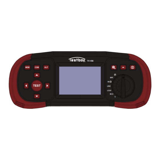
TESTBOY TV 456 Front 3 Description of the instrument 3.1 Front Picture 3.1: Front (Model TESTBOY TV 456) Legend: Function selector Selects the desired function switch 2 Setup button Displays various setting options 3 Exit/Back/Return Exit/back 4 ON/OFF Switches the unit on or off... -
Page 12: Connection Plate
TESTBOY TV 456 Connection plate 3.2 Connection plate Picture 3.2: Connection plate Legend: Test connection Measurement inputs / outputs Socket for probe Protective flap Warnings! The maximum permissible voltage between any test terminal and earth is ❑ 600 V! The maximum permissible voltage between the test connections is 550 V! -
Page 13: Back Cover
TESTBOY TV 456 Back side 3.3 Back cover Picture 3.3: Back Legend: Battery compartment cover Information plate on the back Battery/accumulator compartment cover fixing screw Picture 3.4: Battery compartment Legend: 1 Fuse F1 2 Fuse F2 3 Fuse F3 4 Battery cells... -
Page 14: Structure Of The Display
TESTBOY TV 456 Structure of the display 3.4 Structure of the display Picture 3.5: Typical function display Legend: 1 Function line Shows the selected function 2 Result field Shows main and partial results of the measurement 3 Status bar GOOD/BAD/ABORT/START/WAIT/... -
Page 15: Battery Indicator
TESTBOY TV 456 Structure of the display 3.4.2 Battery indicator The display shows the charge status of battery and whether an external charger is connected. Display of the battery capacity. Weak battery. The battery is too weak to guarantee a correct result. Replace the batteries or recharge the batteries. -
Page 16: Help Screens
TESTBOY TV 456 Structure of the display 3.4.5 Help screens HELP (HELP) Opens the help screen. There are help menus for all functions. The help menu contains schematic diagrams to illustrate how to connect the instrument to the electrical system. After selecting the measurement you want to perform, press the HELP button to view the associated help menu. -
Page 17: Equipment Set And Accessories
TESTBOY TV 456 Equipment set and accessories 3.5 Equipment set and accessories 3.5.1 Standard equipment TESTBOY TV 456 Instrument ❑ Quick guide ❑ Product test data ❑ Declaration of guarantee ❑ Declaration of conformity ❑ Mains measurement cable ❑ Universal test cable ❑... -
Page 18: Operation Of The Instrument
TESTBOY TV 456 Operation of the instrument 4 Operation of the instrument 4.1 Function selection To select a test function, the FUNCTION SELECTOR must be used. Keys: Select the test/measurement function: V Voltage and frequency and phase sequence. ❑ RCD RCD test ❑... -
Page 19: Settings
TESTBOY TV 456 Settings 4.2 Settings To access the setup menu, press the SETUP button. The following settings can be made in the Setup menu: Date/Time: Set internal date and time ❑ Isc factor: Setting the scaling factor for short/error current ❑... -
Page 20: Measurements
Make sure that there are no voltages on the object under test. Connect the test leads to the TV 456. Connect the test cable to the object to be tested (see figure 5.2) to test the Insulation resistance measurement to be carried out. -
Page 21: Continuity Test
TESTBOY TV 456 Measurements Picture 5.2: Connection of the universal test cable Step 4: Check the displayed warnings and the terminal monitor before starting the measurement. When is displayed, press the TEST button. When the measurement is completed, the measurement results are displayed together with the indication or . -
Page 22: R Low Test
TESTBOY TV 456 Measurements Two sub-functions are available for the continuity test: R Low, approx. 240 mA Continuity test with automatic polarity reversal ❑ Continuous continuity test with low current (approx. 4 mA), useful for testing ❑ inductive systems 5.2.1 R Low Test This function checks the resistance between two different points in the installation to ensure that there is a conductive path between them. - Page 23 TESTBOY TV 456 Measurements Connect the test cable to the TV 456. Before performing an R Low measurement, compensate the resistance of the test leads as follows: 1. First short-circuit the test leads as shown in figure 5.5 Picture 5.5: Short-circuited test leads Press the COM key.
-
Page 24: Continuity Test
TESTBOY TV 456 Measurements Picture 5.7: Short-circuited test leads Displayed results: R....Main result of the LowΩ-resistance (average of R+ and R-) R+....Low-resistance partial result with positive voltage at the L terminal R-....Low impedance partial result with positive voltage at N terminal... - Page 25 TESTBOY TV 456 Measurements Picture 5.8: Short-circuited test leads Step 2: Set the following limit value with the navigation keys: Limit: Limitation of the resistance value ❑ Step 3: Connect the test cable to the unit and the object to be tested. Follow the connection diagram shown in figure 5.9 to perform the continuity measurement.
- Page 26 TESTBOY TV 456 Measurements Picture 5.10: Example of the result of a low-current continuity measurement Displayed result: R....Low current resistance as I....Current used for the measurement Warning: Low-current continuity measurements should only be carried out on voltage-free ❑ objects! Notes: If there is a voltage of more than 10 V between the test terminals, the continuity ❑...
-
Page 27: Rcd Test
The selected rated differential current can be multiplied by ½, 1, 2 or 5. 5.3.4 RCD type and test current from polarity The TV 456 enables testing of general (instantaneous) and selective (time-delayed) RCDs. It is suitable for testing the following types of SRCDs, among others: Alternating fault current (AC type) ❑... -
Page 28: Testing Of Selective (Time-Delayed) Rcds
TESTBOY TV 456 Measurements The start polarity of the test current can be started with the positive half-wave at 0° or with the negative half-wave at 180°. Positive start polarity (180°) Negative start polarity (0°) Picture 5.11: Test current with positive or negative half-wave 5.3.5 Testing of selective (time-delayed) RCDs... - Page 29 TESTBOY TV 456 Measurements Step 1: Select the RCD function with the function selector switch and the Uc mode with the navigation keys. The following menu is displayed: Picture 5.12: contact voltage measurement menu Step 2: Set the following measurement parameters and limit values: IΔn: Rated residual current...
- Page 30 TESTBOY TV 456 Measurements Check for any warnings and check the terminal monitor on the display before starting the measurement. If everything is OK and the is displayed, press the TEST button. After the measurement has been taken, the results appear on the display together with Picture 5.14: Example of the results of the contact voltage measurement...
-
Page 31: Rcd Tripping Time (Rcd Time)
TESTBOY TV 456 Measurements 5.3.7 RCD tripping time (RCD Time) The purpose of measuring the tripping time is to check the effectiveness of an RCD. This is achieved by a test in which a suitable fault condition is simulated. The tripping times vary depending on the standard and are listed below. - Page 32 TESTBOY TV 456 Measurements Step 2: Set the following measurement parameters: IΔn: Rated current of the differential release ❑ Type: RCD type ❑ Factor: Nominal multiplier of the RCD ❑ Pole: Start polarity of the test current ❑ Step 3: Connect the leads to the unit and follow the connection diagram shown in figure 5.13...
-
Page 33: Rcd Tripping Current (Rcd Current)
TESTBOY TV 456 Measurements 5.3.8 RCD tripping current (RCD Current) This test is used to determine the minimum current required to trip the RCD. circuit breaker is required. After starting the measurement, the test current generated by the unit is continuously increased, starting at 0.2xIΔN up to 1.1xIΔN (up to 1.5xIΔN / 2.2xIΔN (IΔN =10 mA) for pulsating DC fault currents). -
Page 34: Automatic Test
TESTBOY TV 456 Measurements Picture 5.18: Example of the result of a trip current measurement Displayed result: I....Cut-off current Uci....Contact voltage t....Release time Notes: The parameters set in this function are also transferred to all other RCD ❑ functions. Measurement of the tripping current of the RCD/FI circuit breaker is only carried ❑... - Page 35 TESTBOY TV 456 Measurements To perform the RCD automatic test Step 1: Select the RCD function with the function selector and the Auto mode with the navigation keys. The following menu is displayed: Picture 5.19: RCD automatic test menu Step 2: Set the following measurement parameters: IΔN: Rated current of the RCD...
- Page 36 TESTBOY TV 456 Measurements Picture 5.20: Step 1 RCD automatic test results After the RCD is switched on again, the automatic test sequence automatically continues with step 2. 2. Measurement of the release time with the following measurement parameters: - Test current of IΔN - The test current is started with the negative half-wave at 180°.
- Page 37 TESTBOY TV 456 Measurements Picture 5.22: Step 3 RCD automatic test results After the RCD/FI circuit breaker is switched on again, the automatic test sequence automatically continues with step 4. 4. Measurement of the release time with the following measurement parameters: - Test current of 5xIΔN...
- Page 38 TESTBOY TV 456 Measurements Picture 5.24: Step 5 RCD automatic test results After performing step 5, the automatic test sequence of the RCD/FI circuit breaker continues with step 6. 6. Measurement of the release time with the following measurement parameters: - Test current of ½xIΔN...
- Page 39 TESTBOY TV 456 Measurements Picture 5.26: Step 7 RCD automatic test results 8. Ramp test measurement with the following measurement parameters: - The test current is started with the negative half-wave at 180°. This measurement determines the minimum current required to trip the RCD/FI circuit breaker.
-
Page 40: Fault Loop Impedance And Fault Current
TESTBOY TV 456 Measurements Notes: The x1 auto tests are automatically skipped for RCD type B with rated residual ❑ currents of IΔN = 1000 mA. The x5 autotests are automatically skipped in the following cases: ❑ RCD type AC with rated residual currents of IΔN = 1000 mA RCD type A and B with rated residual currents of IΔN >= 300 mA... - Page 41 TESTBOY TV 456 Measurements Step 1: Select the LOOP function with the function selector and the desired LOOP mode with the navigation keys. Then use the navigation keys to select the desired values for the Type, Time and Current options. The following menu is displayed: Picture 5.28: Loop impedance measurement menu...
-
Page 42: Fault Loop Impedance Test Rcd
TESTBOY TV 456 Measurements Picture 5.30: Example of the results of the loop impedance measurement Displayed results: Z....... Fault loop impedance ISC....Predicted fault current (displayed in amperes) Notes: The specified accuracy of the test parameters is only valid if the mains voltage is ❑... - Page 43 TESTBOY TV 456 Measurements Measurement of the RCD trip limit Step 1: Select the LOOP function with the function selector and the RCD mode with the navigation keys. Then use the navigation keys to select the desired values for the Type, Time and Current options.
- Page 44 TESTBOY TV 456 Measurements Notes: Measuring the fault loop impedance using the trip disable function does not ❑ normally trip an RCD. However, if the trip limit can be exceeded as a result of a leakage current flowing through the PE protective conductor or a capacitive connection between the L and PE conductors.
-
Page 45: Line Impedance And Expected Short Circuit Current
TESTBOY TV 456 Measurements Step 2: Connect the appropriate test leads to the unit and follow the connection diagram shown in Figure 5.29 to perform a loop impedance Rs measurement. Step 3: Check if warnings are displayed on the screen and check the terminal monitor before starting the measurement. - Page 46 TESTBOY TV 456 Measurements Nominal input voltage Voltage range (93 V ≤ 115 V < 134 V) UL-PE (185 V ≤ ≤ 266 V) 230 V UL-PE (321 V ≤ ≤ 485 V) 400 V UL-PE To perform the line impedance measurement: Step 1: Select the LINE function with the function selector.
-
Page 47: Voltage Drop Test
TESTBOY TV 456 Measurements Step 3: Check if warnings are displayed on the screen and check the terminal monitor before starting the measurement. If everything is OK and is displayed, press the TEST button. After the measurement has been carried out, the results are shown on the display: Picture 5.37: Example of the results of the line impedance measurement... - Page 48 TESTBOY TV 456 Measurements with the navigation keys. Then select the desired values for options Type, Time and Current with the navigation keys. The following menu is displayed: Picture 5.38: Voltage drop measurement menu Step 2: Connect the appropriate test leads from the reference point to the unit and follow the connection diagram shown in Figure 5.36 to perform a phase-neutral or phase-phase...
-
Page 49: Phase Sequence Check
TESTBOY TV 456 Measurements Picture 5.39: Example of measurement results of the voltage drop measurement Displayed results: ∆U....Voltage drop of the test point compared to the reference point Zref....Line impedance of the reference point Z....Line impedance of the test point ISC.....Projected short-circuit current of the test point... -
Page 50: Voltage And Frequency
TESTBOY TV 456 Measurements Picture 5.41: Connection diagram of the test cable Step 3: Check if any warnings are displayed on the screen and check the terminal monitor before starting the measurement. The phase sequence test is a continuously running test, therefore the results are displayed as soon as the test lead is fully connected to the unit under test. - Page 51 TESTBOY TV 456 Measurements To perform the voltage measurement: Step 1: Select the function voltage, frequency and phase sequence (V) with the function selector switch. The following menu is displayed: Picture 5.43: Voltage and frequency measurement menu Step 2: Connect the test cable to the unit and follow the connection diagram in Figure 5.44 to perform a voltage and frequency measurement.
-
Page 52: Earth Resistance Measurement
5.8 Earth resistance measurement Earth resistance (Re) 3-wire and 4-wire measurement 5.8.1 method The TV 456 enables earth resistance measurement with the 3-wire and 4-wire measurement method. To perform an earth resistance measurement: Step 1: Select the function Earth resistance measurement (RPE) with the function selector switch and select the mode Re with the navigation keys. - Page 53 TESTBOY TV 456 Measurements Picture 5.46: Earth resistance measurement menu Step 2: Set the following limit value using the navigation keys: Limit: Limitation of the resistance value ❑ Step 3: Follow the connection diagram shown in Figure 5.47 to perform the earth resistance measurement with 4 conductors.
- Page 54 TESTBOY TV 456 Measurements Picture 5.48: 3-wire connection diagram Step 4: Check if any warnings are displayed on the screen and check the terminal monitor before starting the measurement. If everything is OK and is displayed, press the TEST button to start the measurement. The current measurement result is displayed after the measurement with the display or .
-
Page 55: Specific Earth Resistance (Ro)
TESTBOY TV 456 Measurements Specific earth resistance (Ro) 5.8.2 It is advisable to measure the earthing resistance when determining the parameters of the earthing system (required length and surface of the earth electrodes, suitable installation depth of the earthing system, etc.) in order to obtain more accurate calculations. - Page 56 TESTBOY TV 456 Measurements Step 4: Check if any warnings are displayed on the screen and check the terminal monitor before starting the measurement. If everything is OK and is displayed, press the TEST button to start the measurement. The current measurement result is displayed after the measurement with the display or .
-
Page 57: Maintenance
Maintenance 6 Maintenance 6.1 Replacing fuses There are three fuses under the rear battery cover of the TV 456. - F3 M 0.315 A / 250 V, 205 mm This fuse protects the internal circuits of the low-impedance function if the test probes are accidentally connected to the mains voltage. -
Page 58: Technical Data
TESTBOY TV 456 Technical data 7 Technical data 7.1 Replacing the fuse Insulation resistance (nominal voltages 50 VDC) Measuring range according to EN61557 from 50 kΩ - 80 MΩ Measuring range (MΩ) Resolution (MΩ) Tolerance 0.1 - 80 MΩ (0,100 ... 1,999) 0,001 ±... -
Page 59: Contact Resistance
TESTBOY TV 456 Technical data 7.2 Contact resistance Niederohm 7.2.1 Measuring range according to EN61557-4 from 0.1 Ω - 1999 Ω Measuring range (Ω) Resolution (Ω) Tolerance (0.10 Ω ... 19.99 Ω) 0.01 Ω 0,1 - 20,0 ± (3 % + 3 digits) (20.0 Ω... -
Page 60: Contact Voltage
TESTBOY TV 456 Technical data Selection of the RCD test current (effective value calculated on 20 ms) according to IEC 61009: ½ IΔN 1xIΔN 2xIΔN 5xIΔN RCD IΔ IΔN (mA) √ √ √ √ √ √ 10,5 √ √ √... -
Page 61: Fault Loop Impedance And Fault Current
TESTBOY TV 456 Technical data Contact voltage Measuring range (V) Resolution (V) Tolerance 3,0 - 9,9 -0%/+10% + 5 digits 10,0 - 99,9 -0%/+10% + 5 digits 7.4 Fault loop impedance and fault current Zloop L-PE, hypofunction Ipfc The measuring range corresponds to EN 61557-3 for 0.25 - 1999 Ω... -
Page 62: Line Impedance And Short Circuit Current
TESTBOY TV 456 Technical data 7.5 Line impedance and short circuit current Line impedance The measuring range corresponds to EN61557 for 0.25 Ω - 1999 Ω ZLine, L-L, L-N, Ipsc Measuring range (Ω) Resolution (Ω) Tolerance 0,2 - 9999 (0,20 ... 19,99) 0,01 ±5% +5 digits... -
Page 63: Earth Resistance
TESTBOY TV 456 Technical data 7.8 Earth resistance Measurement according to EN61557-5 for 100 - 1999 Ω Measuring range (Ω) Resolution (Ω) Tolerance 1,0 - 9999 (1,00 - 19,99) 0,01 ±5% +5 digits (20,0 - 199,9) 0,1 (200,0 - 9999) 1 Max. -
Page 64: General Data
TESTBOY TV 456 Technical data 7.9 General data Power supply voltage..........9 VDC (61.5-V battery cells, size AA) Power supply adapter..........12 VDC / 1000 mA Battery charging current........< 600 mA Voltage of charged batteries........9 VDC (61.5 V, in fully charged state) Charging time............6 h... -
Page 65: Saving Measurements
"0" are automatically discarded. Before/when taking measurements, make sure that IDs are created! 8.1 Overview - The TV 456 can store up to 1000 measurements - The list of records can be worked through step by step - A single record or all records can be deleted... -
Page 66: Saving Results
TESTBOY TV 456 Saving measurements 8.2 Saving results Step 1: When the measurement is complete (Figure 8.3), the results are displayed on the screen. Picture 8.3: Last results Step 2: Press the MEM button. The following is now displayed (Figure 8.4): Picture 8.4: Saving results... - Page 67 TESTBOY TV 456 Saving measurements Step 3: To change the client ID, location ID or object ID, press the LEFT button. The following screen is displayed (Figure 8.5): Picture 8.5: ID editor Use the navigation keys to select the ID type and change the value of the ID.
-
Page 68: Call Results
TESTBOY TV 456 Saving measurements In addition, the blue function bar receives a coloured field that displays the overall result of the measurement: - Green: measured and passed - Red: measured but not passed - Brown: measured but not evaluated Picture 8.7: Failed result... - Page 69 TESTBOY TV 456 Saving measurements Step 2: Press the UP or DOWN navigation key to find the record you want to delete. Step 3: Press the RIGHT navigation button, the following screen is displayed (Figure 8.8). Picture 8.8: Failed result...
-
Page 70: Usb Communication
9.1 PC software The download of the stored data sets of the TV 456 to the PC is done with the PC application. The records are saved on the PC in the form of a *. csv file. The records can also be exported to an Excel spreadsheet (*.xlsx) for quick reporting and further... - Page 71 TESTBOY TV 456 USB communication Step 4: Click on "Scan Ports" (Picture 9.2). Picture 9.2: Scan ports Step 5: Select the corresponding connection and click on "Open connection" (Figure 9.3). Picture 9.3: opening of the connection Step 6: Click on "Download" to start the data transfer (Figure 9.4). When the records are...
- Page 72 TESTBOY TV 456 USB communication Picture 9.4: Downloading data Step 7: Click on the "Excel" button to export all data sets to an Excel file (Figure 9.5). The exported files are saved by default under "Documents". Picture 9.5: Creating an Excel file...
- Page 73 TESTBOY TV 456 USB communication...
- Page 74 Union) requirements for safety and electromagnetic compatibility. © 2022 TESTBOY The trade names Testboy are registered or pending trademarks in Europe and other countries. No part of this document may be reproduced or used in any form or by any means el...
Need help?
Do you have a question about the TV 456 and is the answer not in the manual?
Questions and answers