Table of Contents
Advertisement
Available languages
Available languages
Quick Links
Инструкция
по эксплуатации
Мегаомметр TESTBOY TV 430N
Цены на товар на сайте:
http://www.vseinstrumenti.ru/instrument/izmeritelnyj/parametry-
setej/soprotivleniya/megaommetry/testboy/pribor-dlya-proverki-soprotivleniya-izolyatsii-testboy-tv-430n/
Отзывы и обсуждения товара на сайте:
http://www.vseinstrumenti.ru/instrument/izmeritelnyj/parametry-
setej/soprotivleniya/megaommetry/testboy/pribor-dlya-proverki-soprotivleniya-izolyatsii-testboy-tv-
430n/#tab-Responses
Advertisement
Table of Contents

Subscribe to Our Youtube Channel
Related Manuals for Testboy TV 430 N


Summary of Contents for Testboy TV 430 N
- Page 1 Инструкция по эксплуатации Мегаомметр TESTBOY TV 430N Цены на товар на сайте: http://www.vseinstrumenti.ru/instrument/izmeritelnyj/parametry- setej/soprotivleniya/megaommetry/testboy/pribor-dlya-proverki-soprotivleniya-izolyatsii-testboy-tv-430n/ Отзывы и обсуждения товара на сайте: http://www.vseinstrumenti.ru/instrument/izmeritelnyj/parametry- setej/soprotivleniya/megaommetry/testboy/pribor-dlya-proverki-soprotivleniya-izolyatsii-testboy-tv- 430n/#tab-Responses...
- Page 2 TV 430 N Isolationswiderstand Messgerät Insulation Resistance Tester Medidor da Resistência do Isolamento Измеритель сопротивления изоляции Bedienungsanleitung 0913 GB Instruction Manual PT lnstruções de serviço RU Инструкция по использованию ...
- Page 3 D Bedienungsanleitung Garantie Dieses Gerät wurde mit Sorgfalt überprüft und wurde frei von material‐ und Konstruktionsfehlern ausgeliefert. Die Garantiezeit beträgt 3 Jahre. Jeder defekt, der innerhalb der dreijährigen Garantiefrist entsteht, wird nach zurücksenden des Gerätes wieder repariert oder instandgesetzt oder kostenlos ersetzt. Von der Garantie ausgeschlossen sind Messleitungen Batterien und Sicherungen. Wurde ein Defekt durch unsachgemäße Handhabung hervorgerufen, wird die Reparatur berechnet. SICHERHEITSINFORMATION Dieses Gerät ist gemäß IEC/EN 61010‐1 bezüglich elektronischer Messgeräte mit einer Meß‐Kategorie (CAT II 600 V) und Verschmutzungsgrad 2 entworfen worden. Warnung Um einen elektrischen Schlag zu vermeiden befolgen Sie bitte folgende Regeln: ‐ Benutzen Sie das Gerät nicht wenn dieses einen Defekt aufweist. Achten Sie besonders auf Schäden am Gehäuse und an der Isolation der Messleitungen und deren Anschlüsse. ‐ Inspizieren Sie die Messleitungen regelmäßig nach fehlerhafter Isolierung und überprüfen Sie den Durchgang. Ersetzen Sie defekte Testleitungen vor dem Benutzen des Gerätes. ‐ Benutzen Sie das Gerät nicht wenn es unnormal funktioniert. Der Schutz vor einem Stromschlag ist nicht mehr gewährleistet, bei Zweifel wenden Sie sich an unseren Service! ‐ Betreiben Sie das Gerät nicht in der Nähe von explosiven Gasen, Stäuben und anderen Stoffen. ‐ Verwenden Sie das Gerät nur innerhalb der auf dem Gerät und in der Anleitung angegebenen Spannungsbereiche. ‐ Überprüfen Sie vor der Benutzung die Funktion des Gerätes durch Messen einer bekannten Spannung. ‐...
-
Page 4: Spezifikationen
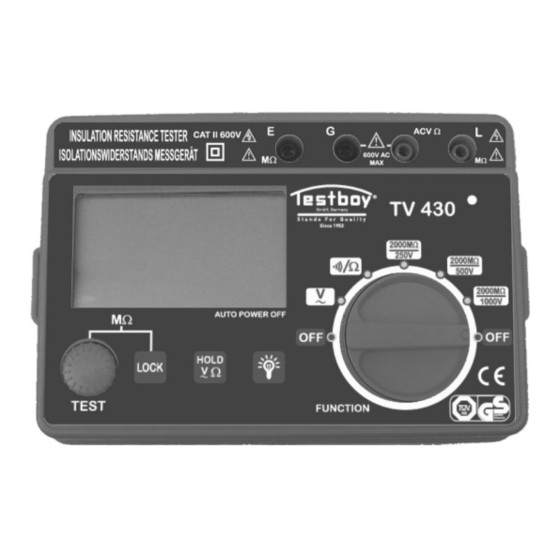
Achtung Um mögliche Schäden an diesem Gerät oder dem Messobjekt zu vermeiden, beachten Sie bitte folgende Hinweise: ‐ Trennen Sie das Messobjekt von der Spannungsversorgung und entladen Sie alle Kapazitäten bevor Sie Widerstand, Isolationswiderstand oder Durchgang prüfen. ‐ Entfernen Sie die Messleitungen vom Messobjekt bevor Sie den Funktionswahlschalter betätigen. ‐ Entfernen Sie die Messleitungen bevor Sie das Gerät öffnen. SYMBOLE AC (Wechselspannung) DC (Gleichspannung) Wichtige Sicherheitsinformation. Siehe Anleitung. Gefährliche Spannung vorhanden. Seien Sie vorsichtig! Erde (Schutzleiter) CE‐konform Schutzisoliert Batterie schwach Allgemeine Beschreibung Zum testen des Isolationswiderstandes kann eine Spannung von 250V, 500V oder 1000V gewählt werden. Ebenso können Widerstände kleiner 200 und Durchgangsprüfungen durchgeführt werden. Es können Transformatoren, Motoren, Kabel, Schalter, elektrische Schaltungen überprüft sowie Isolationsprüfungen durchgeführt werden. Weitere Merkmale ... - Page 5 Gerätebeschreibung 1. LCD‐Anzeige 2. “TEST”‐Taste: Mit dieser Taste starten Sie den Isolationswiderstands‐Test. Nach ca. 30 Sek. wird der Test automatisch gestoppt. Sie können aber auch durch erneutes drücken der Taste den Test jederzeit wieder abbrechen. 3. "LOCK"‐Taste: Drücken Sie diese Taste um den Isolationswiderstands‐Test dauerhaft einzuschalten. Drücken Sie, nachdem Sie die „Test“‐Taste gedrückt haben, die Taste „Lock“ um dauerhaft die Prüfspannung einzuschalten. Dieses wird im Display durch "LOCK" angezeigt. Um den Test wieder abzuschalten drücken Sie erneut die Taste „Test“. 4. "HOLD"‐Taste: Hält den aktuellen Messwert im Display fest. (In den Bereichen ACV und ) Hält den aktuellen Messwert im Display fest im M‐Bereich (mit Außnahme der Dezimalstelle) 5. " "‐Taste Mit dieser Taste schalten Sie die Hintergrundbeleuchtung ein. Nach ca. 15 Sek. schaltet sich die Hintergrundbeleuchtung automatisch wieder ab. 6. Drehschalter Mit dem Drehschalter wählt man die gewünschte Funktion bzw. den gewünschten Messbereich aus. Ebenso wird mit dem Drehschalter das Gerät ein‐ bzw. ausgeschaltet. 7. "E"‐Buchse: Die Testbuchse wird mit dem Masseanschluß des Messobjektes verbunden. 8. "G"‐Buchse: Eingangsbuchse für ACV und Test 9. "ACV "‐Buchse Testbuchse für ACV und Test. 10. "L"‐Buchse Die Testbuchse wird mit dem Messobjekt verbunden. 11. Hochspannungsanzeige Die LED leuchtet nach dem drücken der “Test”‐Taste in der Isolationswiderstandsmessung. Durch leuchten der LED wird angezeigt das Spannung an den Messleitungen anliegt. ...
- Page 6 Identifizieren der Messleitungen 1. Messleitung mit großer Krokoklemme. 2. Hochspannungs Messleitung. 3. Normale Messleitung (Für einfacheres Messen des Isolationswiderstandes kann eine Kroko‐Klemme an der Messspitze befestigt werden. Siehe Bild unten.) Spezifikationen Die Genauigkeit ist spezifiziert bis zu einem Jahr nach Kalibrierung bei 18° bis 28°C, mit einer relative Luftfeuchte kleiner 75%. Die Genauigkeit wird angegeben: ± ([% des Anzeigewertes]+[Zahl des letzten Digits]) Wechselspannung (AC) Bereich Auflösung Genauigkeit 600V 1V ± (1,5%+5) Eingangsimpedanz: 4.5M Frequenzbereich: 45Hz bis 400Hz Widerstand Bereich Auflösung Genauigkeit ±(1.0%+3) 200 0,1 Leerlaufspannung: ca. 2,8V ...
- Page 7 Wenn der Widerstand < 1M ist Buzzer wird der Buzzer aktiv. Bedienung Spannungsmessung WARNUNG: Seien Sie vorsichtig um einen elektrischen Schlag zu vermeiden. Nach abgeschlossener Messung des Isolationswiderstandes entladen Sie bitte das Messobjekt vollständig. Um einen elektrischen Schlag zu vermeiden brühren Sie nicht das Messobjekt. Berühren Sie auch keine unisolierten Stellen am Messobjekt oder am Messgerät. Bleiben Sie immer mit den Fingern hinter den Schutzbarrieren der Messleitungen. Bevor Sie den Isolationswiderstand testen, vergewissern Sie sich das das Messobjekt keine Ladung enthällt. Entladen Sie das Messobjekt vollständig bevor Sie Messen. Wenn Sie den Isolationswiderstand testen, legen Sie keine andere Spannung an das Gerät an. Vor der Messung prüfen Sie bitte ob der richtige Messbereich ausgewählt ist und die Messleitungen korrekt angeschlossen sind. Wenn mit dem Drehschalter der Bereich "2000M/250V", "2000M/500V" oder "2000M/ 1000V” ausgewählt wurde und die „TEST“‐Taste gedrückt wurde, liegt an den Buchsen “E” und "L" eine Spannung von 250V‐1000V an. Berühren sie niemals unisolierte Teile des Messobjektes oder des Messgerätes. Es besteht die Gefahr eines elektrischen Schlages. Wechselspannungsmessung Messen Sie keine Spannungen die größer sind als 600V. Verbinden Sie die Hochspannungsmessleitung mit der Buchse ACV und die normale Messleitung mit der Buchse “G”. Wählen Sie mit dem Drehschalter den Bereich V~ aus und führen Sie die Messung durch. Der gemessene Wert wird im Display angezeigt. Widerstands‐ und Durchgangsmessung: Trennen Sie das Messobjekt von der Spannungsversorgung und entladen Sie das Messobjekt vollständig. Verbinden Sie die Hochspannungsmessleitung mit der ACV Buchse und die normale Messleitung mit der “G” ...
- Page 8 Messung beenden: Nach Drücken des TEST Tasters, zeigt die Hochvolt‐LED das Anliegen hoher Spannung an. Nach 30 Sekunden erlischt diese Anzeige, das bedeutet, dass keine Spannung mehr anliegt und die Messung beendet wurde. Diese Messung kann jederzeit durch erneutes Drücken der TEST Taste beendet werden! Entladen des Testobjektes Das Testobjekt kann durch des Messgerät entladen warden. Halten Sie die Testleitungen an das Testobjekt so lange bis dieses entladen ist. Anmerkung: Bei kapazitiver Belastung achten Sie auf vollständiger Entladung nach jeder Messung um körperliche Verletzungen vorzubeugen! Instandhaltung Dieses Gerät enthält empfindliche Schaltungen, bitte behandeln Sie es mit Sorgfalt. Öffnen Sie das Gehäuse nur, wenn Sie es müssen. Öffnen Sie das Batteriefach nur, wenn alle Messleitungen entfernt wurden und das Gerät ausgeschaltet wird. Wenn das Gerät für längere Zeit nicht mehr benutzt wird, entfernen Sie die Batterien und bewahren Sie das Gerät an einem trockenen und gut belüfteten Platz auf. Verändern Sie nie die Schaltung um eine Zerstörung zu vermeiden. Batteriewechsel Wenn das Symbol “ “ im Dislpay erscheint, wird eine schwache Batterieladung angezeigt. Um die Batterien auszuwechseln entfernen Sie die Schrauben am Batteriefach, ersetzen Sie die alten, verbrauchten batterien mit Batterien gleichen Typs (1,5V, Typ AA, 6 Stück), setzen die Batterieklappe wieder an ihrem Platz und schrauben diese wieder an. Zubehör 1. Spezialmessleitungen 2. Bedienungsanleitung 3. Transporttasche Entsorgung des Gerätes Lieber Kunde, bitte helfen auch Sie unnötigen Abfall zu vermeiden. Entsorgen Sie das Gerät an einer Ihrer kommunalen Sammelstellen für Elektronikschrott. Entsorgen Sie es nicht mit dem Hausmüll. Batterien müssen gesondert entsorgt werden. ...
-
Page 9: Warranty
GB Instruction manual WARRANTY This instrument is warranted to be free from defects in material and workmanship for a period of three years. Any instrument found defective within three years from the delivery date and returned to the factory with transportation charges prepaid, will be repaired, adjusted, or replaced at no Charge to the original purchaser. This warranty dose not cover expandable items such as batteries or fuses. If the defect has been caused by a misuse or abnormal operating conditions, the repair will be billed at a nominal Coat. SAFETY INFORMATION Dieses Gerät ist gemäß IEC/EN 61010‐1 bezüglich elektronischer Messgeräte mit einer Meß‐Kategorie (CAT II 600 V) und Verschmutzungsgrad 2 entworfen worden. This fester has been designed according to IEC‐1010 concerning electronic measuring instruments with a measurement category (CAT II 600 V) and Pollution degree 2. WARNING To avoid possible electric shock or personal Injury, follow these guidelines: ‐ Do not use the meter if it is damaged. Before you use the mater, inspect the case. Pay particular attention to the Insulation surrounding the connectors. ‐ Inspect the test leads for damaged Insulation or metal. Check the fest leads for continuity. Replace damaged fest leads before you use the meter. ‐ Do not use the meter if it operates abnormally. Protection may be impaired. When in doubt, have the meter serviced. ‐ Do not operate the meter around explosive gas, vapor, or dust. ‐ Do not apply more than the rated voltage, as marked on the meter, between terminals or between any terminal and earth ground. ‐ Before use, verify the meters operation by measuring a known voltage. ‐ When servicing the meter, use only specified replacement parts. ‐... -
Page 10: Electrical Symbols
Caution To avoid possible damage to the meter or to the equipment under test, follow these guidelines: ‐ Disconnect circuit power and discharge all high voltage capacitors before testing resistance, insulation resistance, and test for continuity. ‐ Before rotating the range switch to change functions, disconnect test leads from the circuit under test. ‐ Remove test leads from the mater before opening the Meter case. ELECTRICAL SYMBOLS AC (Alternating Current) DC (Direct Current) Important safety information. Refer to the manual. Dangerous voltage may be present. Be cautious! Earth ground Conforms to European Union directives Double Insulated Low battery GENERAL DESCRIPTION This instrument is accurate, reliable and easy to operate. For insulation resistance test, you can change the test voltage among 250V, 500V and 1000V. It can also be used to test ACV, resistance which is lass than 200, and fest for continuity. You can use it to test transformer, motor, cable, switch, electrical appliance as well as to do insulation resistance test. FEATURE ‐ Data hold function ... -
Page 11: Panel Description
PANEL DESCRIPTION 1. LCD 2. “TEST” button: Be used in insulation resistance fest. You can press the Button to start Insulation resistance test, and the test stops about 30 seconds later automatically. At any time, you can press this Button to exit the test. 3. "LOCK" key: Press this key to lock the insulation resistance test. Alter you press "TEST” Button to start insulation resistance test, you can press "LOCK" key to lock the test and the display will show the symbol. Locking the test means that continuous test voltage is provided. To exit locking state, just press "TEST” Button again. 4. "HOLD" key; Hold the present reading on display when in ACV and ranges. Hold the present data an display except the position of the decimal when in M ranges. 5. " "key Used to enable backlight function. About 15 seconds later, the backlight goes off automatically. 6. Rotary Switch Used to select desired function and range as well as to turn on/off the meter. 7. "E" jack: Input jack to be connected to the ground of the object to be tested 8. "G" jack: Input jack (shielding terminal / ground terminal of ACV. test] 9. "ACV” jack ACV. test Input jack ... -
Page 12: Specifications
IDENTIFYING TEST LEADS 1‐ Test lead with a big test Clip. 2 ‐ High‐voltage test lead. 3 ‐ Normal test lead (For insulation resistance test, you can connect an alligator clip to this test leads probe for easy use if necessary. See below figure). SPECIFICATIONS Accuracy is specified for a period of one year alter calibration and at 18°C to 28°C, with relative humidity <75%. Accuracy specifications take the form of: ±([% of Reading]+[number of Least Significant Digits]) AC Voltage Range Resolution Accuracy 600V 1V ± (1,5%+5) Input Impedance: 4.5M Frequency Range: 45Hz to 400Hz Resistance Range Resolution Accuracy ±(1.0%+3) 200 0,1 Open Circuit Voltage: about 2. 8V Overload Protection: 250V Continuity Range Introduction The built‐in buzzer will Open Circuit Voltage: sound if the resistance about 2.8V ... - Page 13 When resistance < 1M, the Buzzer buzzer will sound. Operating Instructions Voltage test WARNING: To avoid electric shock, be cautious. Alter you finish insulation resistance test, discharge die tested object fully. To avoid electric shock, do not touch the object under test and any naked part with your hand or skin. Always place your finger behind the Finger guards an the fest leads when using the probes. Before you do insulation resistance test, you should do the followings: make sure that the object to be tested has no Charge, connect the object to ground and discharge the object fully. When you do Insulation resistance test, don't apply other voltage to the test loop. Before test, make sure that the rotary switch is in correct range and all the connections are tight. After you set the rotary switch in "2000M/250V", "2000M/500V" or "2000M 1000V” range positions and then press "TEST' button, the “E” and "L" terminals will output high voltage of 250V‐1000V. Don`t touch the naked parts of the meter and the object under tast, otherwise, electric shock will occur. AC Voltage Test Don`t attempt to test the voltage which is more than 600V Insert the plug of the high‐voltage test lead Info ACV jack, the plug of the normal test lead into G jack Set the rotary switch in V‐range. Connect the probes across the object to be measured. Read the reading an the display Resistance and Continuity Measurements: Make sure that the object to be measured has no charge. Disconnect power to the object which you want to measure. Insert the plug of the high‐voltage test lead into ACVQ jack, the plug of the normal test lead into G jack. Set the rotary switch in ““ range, Connect the probes across the load to be measured. ...
-
Page 14: Battery Replacement
At any time, you can press TEST button to stop the measurement. Discharge the Tested Object The tested object discharges through the meter. Keep the probes touched to the test points until the abject is completely discharged. Note: For capacitive load, you should discharge it fully alter the measurement to avoid personal injury. Maintenance This instrument is an exact unit, please maintain it carefully. Don open the case unless you need to do so. Before you open battery door, remove all the test leads from the jack first. lf you don't use this meter for a long time, please take out the battery and place the meter in dry and ventilating place. Don`t change the meters circuit to avoid damage. BATTERY REPLACEMENT When the Symbol “ “ appears on the display, it shows that the battery should be replaced. To replace the battery, remove the screws on the battery case, replace the exhausted batteries with new batteries of the same type (1.5V, AA battery, 6 units), rejoin the cover and reinstall the screws. ACCESSORIES 1. Special test leads 2. Manual 3. Transport bag DISPOSAL OF THE ARTICLE Dear Customer, please help avoiding refuse. If you at some point intend to dispose of this article, then please keep in mind that many of its components consist of valuable materials, which can be recycled. Please do not discharge it in the garbage bin, but check with your local council for recycling facilities in your area. ... -
Page 15: Informação De Segurança
PT Manual de Instruções GARANTIA Garante‐se que este aparelho está livre de defeitos relativos a materiais e acabamentos, durante um período de três anos. Qualquer instrumento com defeito dentro dos três anos após a data de entrega e que seja devolvido à fabrica com os portes de transporte pagos, será reparado, retificado ou substituído, sem custos para o comprador inicial. Esta garantia não se estende a pilhas ou fusíveis. Se o defeito tiver sido causado por mau uso ou por condições de funcionamento fora do normal, proceder‐se‐á à cobrança da reparação. INFORMAÇÃO DE SEGURANÇA Este aparelho foi concebido de acordo com a norma IEC‐1010, que respeita os instrumentos de medição eletronica com a categoria de medição (CAT II 600 V) e grau 2 de poluição. AVISO Para evitar cheques elétricos ou ferimentos pessoais, siga as seguintes indicações: ‐ Não utilize o medidor se este estiver danificado. Antes de o utilizar, inspecione o seu revestimento. Preste particular atenção ao isolamento à volta dos conetores. ‐ Inspecione os cabos de teste em termos de metal ou isolamento danificado. Verifique a sua continuidade. Substitua os cabos danificados antes de usar o medidor. ‐ Não utilize o medidor se ele estiver a funcionar de forma anómala. A proteção pode estar reduzida. Em caso de dúvida, mande repara‐lo. ‐ Não trabalhar com o aparelho em ambientes com gases explosivos, vapor ou pó. ‐ Não utilize uma voltagem superior à marcada no medidor, entre os terminais ou entre um terminal e a terra. ‐ Antes de utilizar, verifique o funcionamento do aparelho, procedendo à medição de uma tensão conhecida. ‐ Em caso de reparação, utilize apenas as peças de substituição recomendadas. ‐ Tenha cuidado quando estiver a trabalhar com mais de 30V AC RMS, 42V no máximo, ou 60V DC. Tais voltagens implicam um risco de choque. ... -
Page 16: Descrição Geral
‐ Desligue a energia do circuito e descarregue todos os condensadores de alta voltagem, antes de testar a resistência, o isolamento da resistência e a continuidade. Antes de rodar o comutador de mudança de função, desligue os cabos de teste do circuito a testar. ‐ Remova os cabos de teste antes de abrir o aparelho. SIMBOLOS ELÉTRICOS AC (Corrente Alternada) DC (Corrente continua) Informação de segurança importante. Consulte o manual. Pode estar perante tensão perigosa. Tenha cuidado! Terminal terra Está conforme as diretrizes da União Europeia Isolamento duplo Pilhas fracas DESCRIÇÃO GERAL Este instrumento é preciso, fiável e de fácil utilização. Para testar a resistência do isolamento, pode escolher entre as voltagens de 250V, 500V e 1000V. Também pode ser utilizado para testar correntes e resistências inferiores a 200 e para testar continuidades. Pode ainda ser usado para testar transformadores, motores, cabos, interrutores e eletrodomésticos, assim como para testar a resistência de isolamentos. CARATERISTICAS ADICIONAIS ‐ Função de fixação de dados ‐ A voltagem de teste pode ser mudada através do botão giratório ‐ O LED indica um normal funcionamento em condições de alta tensão ... - Page 17 DESCRIÇÃO DO PAINEL 1. LCD 2. Botão “TEST”: Usado em testes de resistência do isolamento. Premir o botão para realizar o teste; o teste termina automaticamente cerca de 30 segundos depois. Pode premir este botão a qualquer momento para terminar o teste. 3. Tecla "LOCK": Premir esta tecla para bloquear o teste de resistência do isolamento. Depois de premir o botão “TEST”, pode premir a tecla “LOCK” para bloquear o teste e o símbolo surgirá no ecrã. Bloquear o teste significa que é fornecida uma tensão de teste continua. Para sair do bloqueio, premir novamente o botão “TEST”. 4. Tecla "HOLD"; Manter a leitura atual no ecrã no alcance ACV e . Mantenha os dados atuais no ecrã, exceto a posição das décimas no alcance M. 5. Tecla " ” É utilizada para possibilitar a existência de uma luz de fundo. A luz de fundo apaga‐se automaticamente 15 segundos depois. 6. Botão giratório É utilizado para selecionar a função de calibração desejada, bem como para ligar e desligar o medidor. 7. Tomada "E": Tomada de entrada para se ligar ao fio terra do objeto a testar. 8. Tomada "G": Tomada de entrada (terminal de proteção /terminal terra para testes de ACV e ) ...
- Page 18 IDENTIFICAÇÃO DOS CABOS DE TESTE 1‐ Cabo de teste com uma grande pinça. 2 – Cabo de teste de alta tensão. 3 – Cabo normal de teste (Num teste de resistência do isolamento pode ligar‐se uma pinça de alavanca à sonda de cabos de teste para um uso fácil, se necessário. Ver figura abaixo) Pinça de alavanca ESPECIFICAÇÕES A precisão está especificada por um período de um ano após calibração e em 18°C a 28°C, com humidade relativa <75%. As especificações de precisão tomam a forma de ±([% de leitura]+[numero do ultimo digito]) Tensão AC Alcance Resolução Precisão 600V 1V ± (1,5%+5) Impedância de entrada : 4.5M Alcance da frequência: de 45Hz a 400Hz Resistência Alcance Resolução Precisão ±(1.0%+3) 200 0,1 Voltagem do Circuito Aberto: cerca de 2.8V Proteção de Sobrecarga: 250V Continuidade Alcance Introdução A sirene incorporada soará se Voltagem do Circuito a resistência for menor que ...
- Page 19 Quando a resistência é < 1M, a campainha faz‐ Campainha se ouvir. Instruções de funcionamento Teste de Tensão AVISO: Tenha cuidado para evitar choques elétricos. Depois de terminar o teste de resistência do isolamento, descarregue completamente o objeto testado. Para evitar choques elétricos, não toque no objeto a ser testado ou em qualquer parte exposta, com a sua mão ou pele. Coloque sempre o seu dedo por trás dos resguardos e dos cabos de teste, quando estiver a usar as sondas. Antes de fazer o teste de resistência do isolamento, deve fazer o seguinte: certifique‐se de que o objeto a testar não tem corrente, ligue o objeto à terra e descarregue‐o completamente. Quando fizer o teste de resistência do isolamento, não aplique outra voltagem ao quadro de teste. Antes do teste, certifique‐se de que o botão giratório está no alcance correto e que todas as ligações estão bem apertadas. Depois de colocar o botão giratório nas posições de alcance "2000M/250V", "2000M/500V" ou "2000M 1000V” e de premir o botão "TEST', os terminais “E” e "L" irão libertar uma alta tensão de 250V‐1000V. Não toque nas partes expostas do medidor ou do objeto a testar, de outro modo, ocorrerá um choque elétrico. Teste de Tensão de Corrente alternada Não tente testar tensões acima dos 600V. Insira a ficha do cabo de teste de alta tensão na tomada ACV e a ficha do cabo de teste normal na tomada G. Rode o comutador giratório para V. Ligue os cabos ao objeto a medir. Faça a leitura no ecrã. Medições da Resistência e Continuidade: Certifique‐se de que o objeto a medir não tem corrente. Desligue a energia do objeto que deseja medir. Insira a ficha do cabo de teste de alta‐tensão na tomada ACVQ e a ficha do cabo de teste normal, na tomada G. Vire o comutador giratório para a posição ““ e ligue as sondas à carga a ser medida. Faça a leitura no ecrã. Se a resistência for <50 , a campainha incorporada soará. Medição da Resistência do Isolamento Insira a ficha do cabo de teste de alta tensão, na tomada L, a ficha do cabo de teste que tem um grampo grande na ponta, na tomada E e a ficha do cabo de teste normal, na tomada G. O cabo de teste da tomada E é o fio de terra. ...
-
Page 20: Substituição Das Pilhas
Descarregamento do Objeto Testado O objeto testado descarrega‐se através do medidor. Mantenha as sondas encostadas às pontas de teste até o objeto estar completamente descarregado. Nota: Para uma carga capacitiva, deve descarrega‐la totalmente após a medição, a fim de evitar ferimentos pessoais. Manutenção Este instrumento é uma unidade exata. Por favor faça‐lhe uma manutenção cuidadosa. Não abra o invólucro a menos que seja necessário. Antes de abrir a tampa do compartimento das pilhas, primeiramente remova todos os cabos de teste da tomada. Se não usar este medidor durante bastante tempo, retire a pilha e guarde o medidor num local seco e ventilado. Não altere o circuito do medidor para evitar danos. SUBSTITUIÇÃO DAS PILHAS Quando o símbolo “ “ aparece no ecrã, significa que as pilhas devem ser substituídas. Para substituir as pilhas, retire os parafusos do compartimento das pilhas, substitua as pilhas gastas por pilhas novas do mesmo tipo (6 pilhas tipo AA de 1.5V) e coloque novamente a tampa e os parafusos. ACESSORIOS 1. Cabos de teste especiais 2. Manual 3. Bolsa de transporte ELIMINAÇÃO DO PRODUTO Caro cliente, Por favor ajude a evitar o desperdício. Se em qualquer altura decidir eliminar este artigo, por favor lembre‐se que muitos dos seus componentes são materiais valiosos que podem ser reciclados. Por favor, não o descarte juntamente com o lixo doméstico. Informe‐se sobre os pontos de recolha disponíveis na sua área de residência. ... - Page 21 RU Инструкция по использованию Гарантия Данный прибор проверен с особой тщательностью и выпущен без дефектов материала и конструктивных недостатков. Срок гарантии составляет 3 года. Все дефекты, которые возникнут в период трехлетней гарантии, после получения прибора мы исправим, прибор будет отремонтирован или заменен бесплатно. Гарантия не распространяется...
- Page 22 Категория CAT II Категория измерения II определяет измерения электрических схем или приборов, которые подсоединены к низковольтному источнику тока (например, измерения на бытовых приборах, ручных инструментах и аналогичных изделиях). Ни в коем случае не следует использовать прибор для измерения электрических схем и приборов категории измерения III или IV! Внимание...
- Page 23 Технические данные Дисплей: 3 ½ разряда, ЖК Индикация состояния батарей: символ “ ” на дисплее Питание: 6 батарей 1.5В, AA Рабочая температура: 0°C - 40°C, влажность воздуха <75% Температура хранения: -10°C до 50°C, влажность воздуха <85% Выходной ток при проверке сопротивления изоляции: 1,5 мA <...
- Page 24 10. Гнездо "L": Контрольное гнездо соединяется с проверяемым объектом. 11. Индикатор высокого напряжения Светодиод загорается после нажатия кнопки Test при измерении сопротивления изоляции. Горящий светодиод сигнализирует, что измерительные провода находятся под напряжением. Описание измерительных проводов 1. Измерительный провод с большим зажимом типа «крокодил». 2.
- Page 25 Сопротивление изоляции Испытательное напряжение 250 500В 1000В Выходное напряжение Испыт. напряжение X (1 ± 10%) Испытательный ток 1 мA Диапазон индикации 2.000M, 20.00M, 200.00M, 2000M Диапазон измерения 0,25M -2000M) Минимальное разрешение 0,001M Погрешность 0,25M - 200M : ± (3%+3) 200M - 2000M: ±(5%+5) Включается, если...
- Page 26 Измерение сопротивления изоляции Присоедините высоковольтный измерительный провод к гнезду “L”, измерительный провод с большим зажимом типа «крокодил» к гнезду “E”, а обычный измерительный провод - к гнезду “G”. Измерительный провод в гнезде „E“ предназначен для соединения с массой. Измерительный провод в гнезде „L“ соединен с источником напряжения. Измерительный...
- Page 27 Не выбрасывайте прибор вместе с бытовыми отходами. Батареи подлежат отдельной утилизации.
- Page 29 GmbH Elektrotechnische Spezialfabrik Beim Alten Flugplatz 3, 49377 Vechta, Germany Tel: +49(0)4441/89112-10 - Fax: +49(0)4441/84536 Internet: http://www.testboy.de - Email: info@testboy.de...
Need help?
Do you have a question about the TV 430 N and is the answer not in the manual?
Questions and answers