
Subscribe to Our Youtube Channel
Related Manuals for Testboy TV 450


Summary of Contents for Testboy TV 450
-
Page 1: Instruction Manual
TESTBOY TV 450 TESTBOY TV 450 (Type B) Instruction manual Version 1.5, Code no. 20 751 769... - Page 2 Mark on your equipment certifies that this equipment meets the requirements of the EU (European Union) concerning safety and electromagnetic compatibility regulations © 2009 TESTBOY No part of this publication may be reproduced or utilized in any form or by any means without permission in writing from TESTBOY.
-
Page 3: Table Of Contents
Settings ......................22 4.2.1 Language ....................22 4.2.2 Initial settings ...................23 4.2.3 Memory (model TESTBOY TV 450 (TYPE B)) .........24 4.2.4 Date and time (model TESTBOY TV 450 (TYPE B))........24 4.2.5 RCD standard ..................25 4.2.6 Isc factor....................26 4.2.7 Commander support.................26 Measurements ......................28 Voltage, frequency and phase sequence ............28... - Page 4 9.4.1 No disconnecting device or FUSE selected ..........64 9.4.2 RCD selected ...................65 Line impedance and prospective short-circuit current ........65 Resistance to earth (model TESTBOY TV 450 (TYPE B)) ......66 Voltage, frequency, and phase rotation ............66 9.7.1 Phase rotation ..................66 9.7.2 Voltage .....................66...
- Page 5 TESTBOY TV 450 Table of contents Appendix B - Accessories for specific measurements ........72 Appendix F – Country notes................73 List of country modifications ................73 Modification issues ..................73 C.2.1 AT modification - G type RCD ..............73...
-
Page 6: Preface
In order for operator to be familiar enough with performing measurements in general and their typical applications it is advisable to read TESTBOY handbook Guide for testing and verification of low voltage installations. The instrument is equipped with the entire necessary accessory for comfortable testing. -
Page 7: Safety And Operational Considerations
2.1 Warnings and notes In order to maintain the highest level of operator safety while carrying out various tests and measurements, TESTBOY recommends keeping your TESTBOY instruments in good condition and undamaged. When using the instrument, consider the following general warnings: symbol on the instrument means »Read the Instruction manual... - Page 8 Insulation resistance, continuity functions and earth resistance measurements (TESTBOY TV 450 (TYPE B)) can only be performed on de-energized objects. PASS / FAIL indication is enabled when limit is set. Apply appropriate limit value for evaluation of measurement results.
- Page 9 TESTBOY TV 450 Warnings and notes Continuity functions If voltages of higher than 10 V (AC or DC) is detected between test terminals, the continuity resistance test will not be performed. Before performing a continuity measurement, where necessary, compensate test lead resistance.
-
Page 10: Battery And Charging
If the instrument is not to be used for a long period of time, remove all batteries from the battery compartment. Alkaline or rechargeable Ni-Cd or Ni-MH batteries (size AA) can be used. TESTBOY recommends only using rechargeable batteries with a capacity of 2100mAh or above. Do not recharge alkaline battery cells! -
Page 11: New Battery Cells Or Cells Unused For A Longer Period
Ni-Cd cells can be subjected to these chemical effects (sometimes called the memory effect). As a result the instrument operation time can be significantly reduced during the initial charging/discharging cycles of the batteries. In this situation, TESTBOY recommend the following procedure to improve the battery lifetime: Procedure Notes Completely charge the battery. -
Page 12: Standards Applied
Part 3 Loop resistance Part 4 Resistance of earth connection and equipotential bonding Part 5 Resistance to earth (TESTBOY TV 450 (TYPE B) only) Part 6 Residual current devices (RCDs) in TT and TN systems Part 7.Phase sequence Part 10 Combined measuring equipment... -
Page 13: Instrument Description
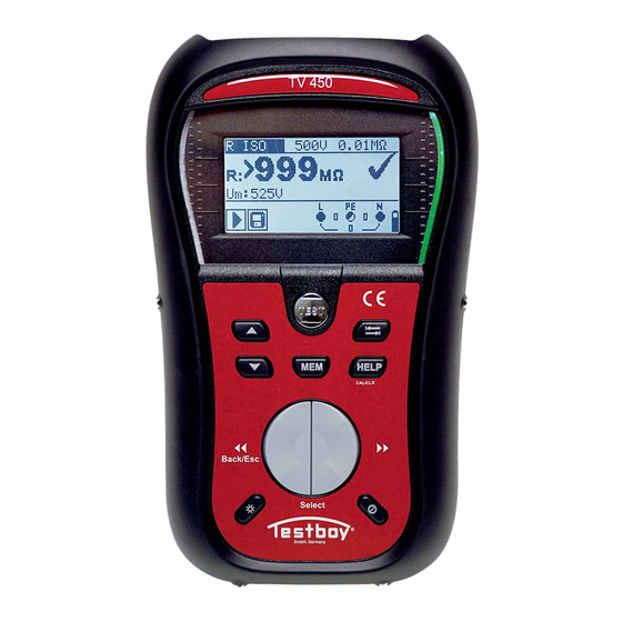
TESTBOY TV 450 Front panel 3 Instrument description 3.1 Front panel Figure 3.1: Front panel (picture of TESTBOY TV 450 (TYPE B)) Legend: * Model TESTBOY TV 450 (TYPE B) ** Model TESTBOY TV 450 1 LCD 128 x 64 dots matrix display with backlight. - Page 14 TESTBOY TV 450 Front panel Accesses help menus. HELP In RCD Auto toggles between top and bottom parts of results field. 10 TAB Selects the parameters in selected function. 11 PASS Green indicator Indicates PASS/ FAIL of result. 12 FAIL...
-
Page 15: Connector Panel
TESTBOY TV 450 Connector panel 3.2 Connector panel Figure 3.2: Connector panel (picture of TESTBOY TV 450 (TYPE B)) Legend: * Model TESTBOY TV 450 (TYPE B) ** Model TESTBOY TV 450 Test connector Measuring inputs / outputs Protection cover... -
Page 16: Back Side
TESTBOY TV 450 Back side 3.3 Back side Figure 3.3: Back side Legend: Side belt Battery compartment cover Fixing screw for battery compartment cover Back panel information label Holder for inclined position of the instrument Magnet for fixing instrument close to tested item (optional) Figure 3.4: Battery compartment... -
Page 17: Display Organization
TESTBOY TV 450 Display organization 3.4 Display organization Function name Result field Test parameter field Message field Terminal voltage Figure 3.5: Typical function monitor display Battery indication 3.4.1 Terminal voltage monitor The terminal voltage monitor displays on-line the voltages on the test terminals and information about active test terminals. -
Page 18: Result Field
RCD tripped-out during the measurement (in RCD functions). Instrument is overheated. The measurement is prohibited until the temperature decreases under the allowed limit. Result(s) can be stored. (model TESTBOY TV 450 (TYPE B)) High electrical noise was detected during measurement. Results may be impaired. -
Page 19: Backlight And Contrast Adjustments
TESTBOY TV 450 Display organization Figure 3.6: Examples of help screens 3.4.7 Backlight and contrast adjustments With the BACKLIGHT key backlight and contrast can be adjusted. Click Toggles backlight intensity level. Locks high intensity backlight level until power is turned off or the Keep pressed for 1 s key is pressed again. -
Page 20: Instrument Set And Accessories
Crocodile clip. 3 pcs Set of NiMH battery cells Power supply adapter CD with instruction manual, and “Guide for testing and verification of low voltage installations” handbook and PC software TESTBOY TV 450 Set of carrying straps RS232 - PS/2 cable USB cable 3.5.3 Optional accessories... -
Page 21: Instrument Operation
<Zline> Line impedance. FUNCTION <Zloop> Fault loop impedance. SELECTOR <RCD> RCD testing. <EARTH RE> Resistance to earth (model TESTBOY TV 450 (TYPE B)). <SETTINGS> General instrument settings. UP/DOWN Selects sub-function in selected measurement function. Selects the test parameter to be set or modified. -
Page 22: Settings
Selection of reference standard for RCD test, Entering Isc factor, Commander support. Additional options in model TESTBOY TV 450 (TYPE B) are: Recalling and clearing stored results, Setting the date and time, Figure 4.1: Options in Settings menu Keys: UP / DOWN Selects appropriate option. -
Page 23: Initial Settings
Customized settings will be lost when this option is used! If the batteries are removed for more than 1 minute the custom made settings will be lost. The default setup is listed below: * model TESTBOY TV 450 (TYPE B) Instrument setting Default value Contrast... -
Page 24: Memory (Model Testboy Tv 450 (Type B))
Selects option. TEST Enters selected option. Function selectors Exits back to main function menu. 4.2.4 Date and time (model TESTBOY TV 450 (TYPE B)) In this menu date and time can be set. Figure 4.5: Setting date and time Keys: Selects the field to be changed. -
Page 25: Rcd Standard
TESTBOY TV 450 Settings 4.2.5 RCD standard In this menu the used standard for RCD tests can be set. Figure 4.6: Selection of RCD test standard Keys: Selects standard. UP / DOWN TEST Confirms selected standard. Function selectors Exits back to main function menu. -
Page 26: Isc Factor
TESTBOY TV 450 Settings Maximum test times related to selected test current for general (non-delayed) RCD Standard ½×I 2×I 5×I ΔN ΔN ΔN ΔN EN 61008 / EN 61009 300 ms 300 ms 150 ms 40 ms EN 60364-4-41 1000 ms... - Page 27 TESTBOY TV 450 Settings Keys: UP / DOWN Selects commander option. TEST Confirms selected option. Function selectors Exits back to main function menu. Note: This option is intended to disable the commander’s remote keys. In the case of high EM interfering noise the operation of the commander’s key can be irregular.
-
Page 28: Measurements
TESTBOY TV 450 Voltage, frequency, phase sequence 5 Measurements 5.1 Voltage, frequency and phase sequence Voltage and frequency measurement is always active in the terminal voltage monitor. In the special VOLTAGE TRMS menu the measured voltage, frequency and information about detected three-phase connection can be stored. Phase sequence measurement conforms to the EN 61557-7 standard. - Page 29 TESTBOY TV 450 Voltage, frequency, phase sequence Voltage measurement procedure * model TESTBOY TV 450 (TYPE B) Select the VOLTAGE TRMS function using the function selector switch. Connect test cable to the instrument. Connect test leads to the item to be tested (see figures 5.2 and 5.3).
-
Page 30: Insulation Resistance
TESTBOY TV 450 Insulation resistance 5.2 Insulation resistance The Insulation resistance measurement is performed in order to ensure safety against electric shock through insulation. It is covered by the EN 61557-2 standard. Typical applications are: Insulation resistance between conductors of installation,... - Page 31 TESTBOY TV 450 Insulation resistance Insulation resistance measuring procedure * model TESTBOY TV 450 (TYPE B) Select the function using the function selector switch. Set the required test voltage. Enable and set limit value (optional). Disconnect tested installation from mains supply (and discharge insulation as required).
-
Page 32: Resistance Of Earth Connection And Equipotential Bonding
See chapter 4.1 Function selection for instructions on key functionality. Figure 5.8: 200 mA RLOW Ω Test parameters for resistance measurement * model TESTBOY TV 450 (TYPE B) TEST Resistance measurement sub-function [R LOWΩ, CONTINUITY*] Maximum resistance [OFF, 0.1 Ω ÷ 20.0 Ω]... -
Page 33: R Lowω, 200 Ma Resistance Measurement
Figure 5.9: Connection of 3-wire test lead plus optional extension lead Resistance to earth connection and equipotential bonding measurement procedure * model TESTBOY TV 450 (TYPE B) Select continuity function using the function selector switch. Set sub-function to R LOWΩ. -
Page 34: Continuous Resistance Measurement With Low Current (Model Testboy Tv 450 (Type B))
TESTBOY TV 450 Resistance of earth connection 5.3.2 Continuous resistance measurement with low current (model TESTBOY TV 450 (TYPE B)) In general, this function serves as standard Ω-meter with a low testing current. The measurement is performed continuously without polarity reversal. The function can also be applied for testing continuity of inductive components. -
Page 35: Compensation Of Test Leads Resistance
The lead compensation is therefore a very important feature to obtain correct result. Each of R LOWΩ and CONTINUITY (model TESTBOY TV 450 (TYPE B)) has own compensation. symbol is displayed if the compensation was carried out successfully. -
Page 36: Testing Rcds
Pulsating residual current (A type, marked with symbol). Model TESTBOY TV 450 (Type B): DC residual current (B type, marked with symbol). Time delayed RCDs have delayed response characteristics. As the contact voltage pre- test or other RCD tests influence the time delayed RCD it takes a certain period to recover into normal state. -
Page 37: Contact Voltage (Rcd Uc)
ΔN the RCD and then normalized to the rated I ΔN Contact voltage measurement procedure * model TESTBOY TV 450 (TYPE B) Select the function using the function selector switch. Set sub-function Uc. Set test parameters (if necessary). -
Page 38: Trip-Out Time (Rcdt)
5.4.2 Trip-out time (RCDt) Trip-out time measurement verifies the sensitivity of the RCD at different residual currents. Trip-out time measurement procedure * model TESTBOY TV 450 (TYPE B) Select the function using the function selector switch. Set sub-function RCDt. Set test parameters (if necessary). -
Page 39: Trip-Out Current (Rcd I)
Maximum test current is I (trip-out current) or end value in case the RCD didn’t trip-out. Δ Trip-out current measurement procedure * model TESTBOY TV 450 (TYPE B) Select the function using the function selector switch. Set sub-function RCD I. -
Page 40: Rcd Autotest
Additional key: HELP / DISPLAY Toggles between top and bottom part of results field. RCD autotest procedure * model TESTBOY TV 450 (TYPE B) RCD Autotest steps Notes Select the function using the function selector switch. - Page 41 TESTBOY TV 450 Testing RCD Result examples: Step 1 Step 2 Step 3 Step 4 Step 5 Step 6 Step 7 Step 8 Figure 5.21: Individual steps in RCD autotest Bottom Figure 5.22: Two parts of result field in RCD autotest...
- Page 42 TESTBOY TV 450 Testing RCD Displayed results: , I Δ N, 0º), x1 ..Step 1 trip-out time ( , I Δ N, 180º), x1 ..Step 2 trip-out time ( , 5 × I Δ N, 0º), x5 ..Step 3 trip-out time ( , 5 ×...
-
Page 43: Fault Loop Impedance And Prospective Fault Current
TESTBOY TV 450 Fault loop impedance 5.5 Fault loop impedance and prospective fault current Fault loop is a loop comprised by mains source, line wiring and PE return path to the mains source. The instrument measures the impedance of the loop and calculates the short circuit current. - Page 44 TESTBOY TV 450 Fault loop impedance Fault loop impedance measurement procedure * model TESTBOY TV 450 (TYPE B) Select the Zloop Zs rcd subfunction using the function selector switch and keys Select test parameters (optional). Connect test cable the TESTBOY TV 450.
-
Page 45: Line Impedance And Prospective Short-Circuit Current
Connections for measurement of line impedance Figure 5.27: Phase-neutral or phase-phase line impedance measurement – connection of plug commander and 3-wire test lead Line impedance measurement procedure * model TESTBOY TV 450 (TYPE B) Select the Z-LINE function using the function selector switch. - Page 46 TESTBOY TV 450 Earth resistance Line to neutral Line to line Figure 5.28: Examples of line impedance measurement result Displayed results: Z ....Line impedance, ....Prospective short-circuit current, Lim ..Low limit prospective short-circuit current value or high limit line impedance value for the UK version.
-
Page 47: Earth Resistance (Model Testboy Tv 450 (Type B))
TESTBOY TV 450 Earth resistance 5.7 Earth resistance (model TESTBOY TV 450 (TYPE B)) Earth resistance is one of the most important parameters for protection against electric shock. Main earthing arrangements, lightning systems, local earthings, etc can be verified with the earthing resistance test. The measurement conforms to the EN 61557- 5 standard. - Page 48 TESTBOY TV 450 Earth resistance Figure 5.31: Resistance to earth, measurement of a lighting protection system Earth resistance measurements, common measurement procedure Select EARTH function using the function selector switch. Enable and set limit value(optional). Connect test leads to the instrument Connect the item to be tested (see figures 5.30, 5.31).
-
Page 49: Pe Test Terminal
TESTBOY TV 450 PE test terminal 5.8 PE test terminal It can happen that a dangerous voltage is applied to the PE wire or other accessible metal parts. This is a very dangerous situation since the PE wire and MPEs are considered to be earthed. - Page 50 TESTBOY TV 450 PE test terminal PE terminal test procedure Connect test cable to the instrument. Connect test leads to the to the item to be tested (see figures 5.33 and 5.34 ). Touch PE test probe (the TEST key) for at least one second.
-
Page 51: Data Handling (Model Testboy Tv 450 (Type B))
Test results can be organized and grouped in a structured manner that reflects the structure of typical electrical installations. Customized names of data structure elements can be uploaded from TESTBOY TV 450 PC SW. Simple browsing through structure and results. - Page 52 TESTBOY TV 450 Memory organization Data structure field Memory operation menu Data structure field level: OBJECT: Default location name (object and its successive number). level: BLOCK: Default location name (block and its successive number). level: FUSE: Default location name (fuse and its successive number).
-
Page 53: Storing Test Results
TESTBOY TV 450 Storing test results 6.3 Storing test results After the completion of a test the results and parameters are ready for storing ( icon is displayed in the information field). By pressing the MEM key, the user can store the results. -
Page 54: Recalling Test Results
TESTBOY TV 450 Recalling test results 6.4 Recalling test results Press the MEM key in a main function menu when there is no result available for storing or select MEMORY in the SETTINGS menu. Figure 6.3: Recall menu - installation Figure 6.4: Recall menu - measurements... -
Page 55: Clearing Stored Data
TESTBOY TV 450 Clearing stored data 6.5 Clearing stored data 6.5.1 Clearing complete memory content Select CLEAR ALL MEMORY in MEMORY menu. A warning will be displayed. Figure 6.6: Clear all memory Keys in clear all memory menu TEST Confirms clearing of complete memory content. -
Page 56: Clearing Individual Measurements
TESTBOY TV 450 Clearing stored data Enters measurements field deleting individual measurements. Keys in dialog for confirmation to clear results in selected location: TEST Deletes all results in selected location. Exits back to delete results menu without changes. Function selectors Exits back to main function menu without changes. -
Page 57: Renaming Installation Structure Elements
6.5.4 Renaming installation structure elements Default installation structure elements are ‘Object’, ‘D.Board’, ‘Circuit’, ‘Electrode’ and ‘Circuit’. In the PC SW package TESTBOY TV 450 default names can be changed with customized names that corresponds the installation under test. Refer to PC SW TESTBOY TV 450 HELP menu for information how to upload customized installation names to the instrument. -
Page 58: Communication
The PC and the instrument will automatically recognize each other. The instrument is prepared to download data to the PC. The program TESTBOY TV 450 is a PC software running on Windows 95/98, Windows NT, Windows 2000, Windows XP, Windows Vista. Read the file README_TESTBOY TV 450.txt on CD for instructions about installing and running the program. -
Page 59: Upgrading The Instrument
TESTBOY TV 450 Upgrading the instrument 7 Upgrading the instrument The instrument can be upgraded from a PC via the RS232 communication port. This enables to keep the instrument up to date even if the standards or regulations change. The upgrade can be carried with help of a special upgrading software and the communication cable as shown on Figure 6.13 . -
Page 60: Maintenance
TESTBOY TV 450 Maintenance 8 Maintenance Unauthorized persons are not allowed to open the TESTBOY TV 450 instrument. There are no user replaceable components inside the instrument, except the battery and fuse under rear cover. 8.1 Fuse replacement There is a fuse under back cover of the TESTBOY TV 450 instrument. -
Page 61: Technical Specifications
TESTBOY TV 450 Technical specification 9 Technical specifications 9.1 Insulation resistance Insulation resistance (nominal voltages 50 V , 100 V and 250 V Measuring range according to EN61557 is 0.15 M Ω ÷ 199.9 M Ω . Measuring range (M Ω ) Resolution (M Ω... -
Page 62: Continuity
Test lead compensation.....up to 5 Ω 9.3 RCD testing Note: All data (marked with “*”) regarding B type RCDs are valid for model TESTBOY TV 450 (TYPE B) only. 9.3.1 General data Nominal residual current (A,AC) ..10 mA, 30 mA, 100 mA, 300 mA, 500 mA, 1000 mA Nominal residual current accuracy..-0 / +0.1 ⋅... -
Page 63: Contact Voltage Rcd-Uc
TESTBOY TV 450 Technical specification IΔN × 1/2 IΔN × 1 IΔN × 2 IΔN × 5 RCD IΔ AC A B* IΔN (mA) 100 100 10.5 15 120 150 212 300 400 500 707 1000 150 105 n.a. 1500 n.a. n.a. -
Page 64: Fault Loop Impedance And Prospective Fault Current
TESTBOY TV 450 Technical specification 0.2 × I ÷ 2.2 × I 0.05 × I ± 0.1 × I (A type, I <30 mA) ΔN ΔN ΔN ΔN ΔN 0.2 × I ÷ 2.2 × I 0.05 × I ± 0.1 × I (B type)* ΔN... -
Page 65: Rcd Selected
TESTBOY TV 450 Technical specification 9.4.2 RCD selected Fault loop impedance Measuring range according to EN61557 is 0.46 Ω ÷ 9.99 k Ω . Measuring range ( Ω ) Resolution ( Ω ) Accuracy 0.00 ÷ 9.99 0.01 ± (5 % of reading + 10 digits) 10.0 ÷... -
Page 66: Resistance To Earth (Model Testboy Tv 450 (Type B))
TESTBOY TV 450 Technical specification 9.6 Resistance to earth (model TESTBOY TV 450 (TYPE B)) Measuring range according to EN61557-5 is 2.00 Ω ÷ 1999 Ω . Measuring range ( Ω ) Resolution ( Ω ) Accuracy 0.00 ÷ 19.99 0.01... -
Page 67: Online Terminal Voltage Monitor
10 ÷ 550 ± (2 % of reading + 2 digits) 9.8 General data Models TESTBOY TV 450 and TESTBOY TV 450 (TYPE B): (6 × 1.5 V battery or accu, size AA) Power supply voltage......9 V Operation.......... typical 20 h Charger socket input voltage .... -
Page 68: A Appendix A - Fuse Table
TESTBOY TV 450 Appendix A A Appendix A - Fuse table A.1 Fuse table - IPSC Fuse type NV Rated Disconnection time [s] current Min. prospective short- circuit current (A) 32.5 22.3 18.7 15.9 65.6 46.4 38.8 31.9 18.7 102.8 56.5... - Page 69 TESTBOY TV 450 Appendix A 919.2 464.2 266.9 1217.2 821.7 663.3 319.1 1567.2 1133.1 964.9 836.5 447.9 2075.3 1429 1195.4 1018 585.4 Fuse type B Rated Disconnection time [s] current Min. prospective short- circuit current (A) Fuse type C Rated...
-
Page 70: Fuse Table - Impedances (Uk)
TESTBOY TV 450 Appendix A Fuse type D Rated Disconnection time [s] current Min. prospective short- circuit current (A) 10.8 21.6 32.4 70.2 86.4 172.8 A.2 Fuse table - impedances (UK) Fuse type B Fuse type C Rated Disconnection time [s]... - Page 71 TESTBOY TV 450 Appendix A Fuse type D Fuse type BS 1361 Rated Disconnection time [s] Rated Disconnection time [s] current current Max. loop impedance ( Ω ) Max. loop impedance ( Ω ) 1,536 1,536 8,36 13,12 0,92 0,92...
-
Page 72: B Appendix B - Accessories For Specific Measurements
Continuous resistance Test lead, 3 x 1.5 m measurement (model Tip commander (A 1270) TESTBOY TV 450 (TYPE Test lead, 4 m (A 1012) Line impedance Test lead, 3 x 1.5 m Plug commander (A 1272) Mains measuring cable Tip commander (A 1270) -
Page 73: C Appendix F – Country Notes
The instrument is intended for testing of general (non-delayed) and selective (time-delayed) RCDs, which are suited for: Alternating residual current (AC type, marked with symbol), Pulsating residual current (A type, marked with symbol). Model TESTBOY TV 450 (TYPE B): DC residual current (B type, marked with symbol). - Page 74 ΔN < 30 mA 2 × 2 × 1.05 × I ΔN 2 × 1.05 × I Model TESTBOY TV 450 (Type B) ΔN only 2 × 2 × 1.05 × I ΔN Table C.1: Relationship between Uc and I Δ...
- Page 75 TESTBOY TV 450 Appendix C...
- Page 76 TESTBOY TV 450 Appendix C...
Need help?
Do you have a question about the TV 450 and is the answer not in the manual?
Questions and answers