
Related Manuals for NSD MELSEC iQ-R VS-R262BH-V1R


Summary of Contents for NSD MELSEC iQ-R VS-R262BH-V1R
- Page 1 ZEF005541702 MELSEC iQ-R PLC Module Converter VS-R262BH-V1R User’s Manual Applicable sensor VRE-P061 VRE-P074 VRE-P097 VRE-P101...
-
Page 3: Table Of Contents
CONTENTS SAFETY PRECAUTIONS ..............................i INTRODUCTION ................................iv RELEVANT MANUALS ..............................iv TRADEMARKS .................................. iv REVISION HISTORY ................................. v 1. OVERVIEW ............................1 1.1 Features ..................................3 1.2 Definitions ..................................4 2. SYSTEM CONFIGURATION ......................5 2.1 Overall Configuration ..............................5 2.2 Applicable System ................................ - Page 4 6. INTER-MODULE SYNCHRONIZATION FUNCTION ............... 35 6.1 Operation ..................................35 6.2 Settings ..................................36 6.3 Readout of the synchronous value ..........................36 7. ONLINE MODULE CHANGE FUNCTION ..................37 7.1 Settings ..................................37 7.2 REPLACEMENT PROCEDURE ..........................38 7.2.1 Changing a module by controlling special relays and special registers ............... 38 7.2.2 Changing a module directly ..........................
-
Page 5: Safety Precautions
NSD. This product is designed to be used under the industrial environments categorized in Class A device. The supplier and user may be required to take appropriate measures. -
Page 6: Installation Precautions
【Installation Precautions】 WARNING - Be sure to shut off all power before mounting/removing this module. Failure to do this could result in equipment damage. CAUTION - Use the programmable controller in an environment that meets the general specifications in the Safety Guidelines included with the base unit. -
Page 7: Disposal Precautions
【Start-up and Maintenance Precautions】 WARNING - Be sure to shut off all power before cleaning this module or tightening screws. Failure to do so may result in failure or malfunction of this module. Loose screws can cause drops of the screws, short circuit or malfunction. Over-tightening screws may damage the screws and/or the module, This can cause drops, short circuit or malfunction. -
Page 8: Introduction
INTRODUCTION Thank you for purchasing the VS-R262BH module. Always read through this manual, and fully comprehend the functions and performance of VS-R262BH before starting use to ensure correct usage of this product. Please submit this manual to the end user. RELEVANT MANUALS VS-R262BH is a module for MELSEC iQ-R. -
Page 9: Revision History
REVISION HISTORY The document No. appears at the upper right of this manual's cover page. Document No. Date Revision Description ZEF005541700 8, Aug., 2018 1st Edition Japanese document: ZEF005541201 ZEF005541701 31, May, 2019 2nd Edition Japanese document: ZEF005541202 ZEF005541702 15, Dec., 2022 3rd Edition Japanese document: ZEF005541202... -
Page 10: Overview
1. OVERVIEW 1. OVERVIEW This user's manual contains the specifications, and operation/programming procedures for VS-R262BH-V1R (*1) which is to be used in combination with a Mitsubishi Electric Corporation. MELSEC iQ-R Series programmable controller. VS-R262BH combines a rotary position sensor to detect the position of the machine being controlled. VS-R262BH is used with the ABSOCODER sensor (turn type). - Page 11 Current Position Detection Function VS-R262BH's current position detection function detects the current position using an ABSOCODER sensor. Conventionally, this was detected using an incremental format encoder in conjunction with a counter unit. The above conventional method has several disadvantages; origin-point return is necessary when power supply is interrupted due to power failure, etc.
-
Page 12: Features
1.1 Features VS-R262BH has the following features: (1) High reliability An absolute position detection format ensures accurate position detection even if a power interruption or unexpected noise condition occurs. An origin returning operation is not required. (2) High resolution The turn-type ABSOCODER sensor (the VRE series) offers a resolution factor of 8192 divisions per 1 turn of the sensor shaft. -
Page 13: Definitions
1.2 Definitions (1) ABSOCODER ABSOCODER is the generic name given to the NSD-developed position sensor which detects rotational/linear displacement, speed, and acceleration, using an absolute position detection method with a digital (or analog) output. ABSOCODER consists of two main components:... -
Page 14: System Configuration
2. SYSTEM CONFIGURATION 2. SYSTEM CONFIGURATION 2.1 Overall Configuration The overall configuration of the Mitsubishi Electric Corporation. MELSEC iQ-R Series using VS-R262BH is shown below. RxxCPU I/O Module Main base unit (R3[ ]B) Refer to the remarks below. Extension cable (RC[ ]B) VS-R262BH ABSOCODER cable Extension base unit (R6[ ]B) -
Page 15: Applicable System
VS-R262BH can be used in the following system. (1) Applicable CPU module Refer to NSD web site for CPU module models with which VS-R262BH can be used. (2) Number of mountable modules Pay attention to the power supply capacity before mounting modules. -
Page 16: Vs-R262Bh Specifications
3. VS-R262BH SPECIFICATIONS 3. VS-R262BH SPECIFICATIONS Shown below are the VS-R262BH specifications. For the ABSOCODER sensor specifications, refer to Appendix 2, "ABSOCODER SENSOR SPECIFICATIONS". 3.1 General Specifications Table 3.1 General Specifications Items Specifications 0 to 55℃ Operating ambient temperature -25 to 75℃ Storage ambient temperature Operating ambient humidity 5 to 95%RH, non-condensing... -
Page 17: Performance Specifications
3.2 Performance Specifications Table 3.2 Performance Specifications Items Specifications Remarks Number of position detection axes Position detection method Absolute format Number of divisions 8192 divisions × 1 turn - Current position detection function Function - Current position setting function Version seal is *C or Sampling time [ms] later... -
Page 18: Input/Output Signals Between Vs-R262Bh And Plc Cpu
3.4 Input/Output Signals between VS-R262BH and PLC CPU The input and output signals to the PLC CPU are shown below. (1) In the table below, the input/output signals are classified as follows: (a) Device X: Input signals from VS-R262BH to PLC CPU. (b) Device Y: Output signals from PLC CPU to VS-R262BH. -
Page 19: Input/Output Signal Details
3.4.1 Input/output signal details The ON/OFF timing and other conditions for signal input/output between VS-R262BH and PLC CPU are explained below. (1) Unit ready (X0) This signal comes OFF when a watchdog timer error is detected by VS-R262BH’s self-diagnosis function. When ‘X0’... - Page 20 (6) PLC ready signal (Y10) This signal is used to switch VS-R262BH’s operation status (online/offline). Y10 ON ········ Online Y10 OFF ······· Offline *: Current position setting cannot be executed at the “offline” status. (7) Error reset signal (Y1C) The following error detection signals will go OFF when ‘Y1C’ (error reset signal) turns ON by the sequence program after correcting a cause of the error.
-
Page 21: Buffer Memory
3.5 Buffer Memory VS-R262BH contains a buffer memory which is used for data communication with the PLC CPU. Data readout of all areas can be executed by the sequence program. Buffer memory space is provided for 2 axes (same content). Addresses 0 to 807 are for axis-1, and addresses 1000 to 1807 are for axis-2. -
Page 22: Sensor Value Storage Area (Address 0, 1 [1000, 1001])
3.5.1 Sensor value storage area (Address 0, 1 [1000, 1001]) The raw sensor value detected by the ABSOCODER sensor is stored in this area as a binary value. The range for raw sensor value is as follows: - Single-turn type VRE: 0 to 8191 (0 to 1FFFH) - The sensor value increases when the input shaft of ABSOCODER sensor rotates in the CW direction. -
Page 23: Error Code Storage Area (Address 7 [1007])
3.5.4 Error code storage area (Address 7 [1007]) This is the area where error codes are stored when errors occur. For error code details, refer to Section 8.1. (1) Error codes are stored as binary values. (2) This storage area is cleared by any of the following actions: - When turning the Y1C (error reset) signal ON by the sequence program - When the PLC CPU is reset - When turning ON the PLC power supply again... -
Page 24: Axis Enabled/Disabled Setting Area (Address 702 [1702])
3.5.7 Axis enabled/disabled setting area (Address 702 [1702]) This area determines whether to enable or disable a particular axis. When buffer memory address 702 is set to "99", the axis-1 will be disabled. When buffer memory address 1702 is set to "99", the axis-2 will be disabled. This area can be written at any time by the sequence program. - Page 25 MEMO...
-
Page 26: Handling And Wiring
4. HANDLING and WIRING 4. HANDLING and WIRING This section explains how to unpack and connect VS-R262BH. 4.1 VS-R262BH Handling Precautions The following precautions should be observed when handling VS-R262BH. (1) As VS-R262BH is constructed from a resin-based material, it should not be dropped or subjected to severe shocks. -
Page 27: Absocoder Sensor Installation Precautions
4.3 ABSOCODER Sensor Installation Precautions The installation conditions and precautions for the ABSOCODER sensor are described in this section. 4.3.1 Installation of ABSOCODER sensor ● Handling of Turn-type ABSOCODER sensor Item Explanation 1) Main unit 2) Cable ● Mounting of Turn-type ABSOCODER sensor Item Explanation Precaution... - Page 28 ● Mounting of Turn-type ABSOCODER sensor Item Explanation Precaution A “direct-link” format will 1) Coupling of machine result in shaft fatigue shaft and sensor and / or breakage after shaft long periods. Therefore, be sure to use a coupling device to link the shafts.
-
Page 29: Precautions For Connecting Absocoder Sensors
● Coupling of Turn-type ABSOCODER sensor Item Explanation Precaution The selection of a larger 1) Coupling device coupling than necessary selection precaution will increase the shaft load which is caused by the mounting error amount. Excessive force applied to the shaft can deform the coupling and reduce durability. -
Page 30: Name Of Parts
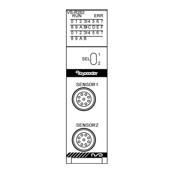
4.4 Name of Parts The illustration below shows the nomenclature of VS-R262BH. Operation status display area Name Description Displays the operation state of VS-R262BH. ON: Normal operation Blinking (400ms intervals): When selecting a module which is changed RUN LED online OFF: when the watch dog timer error occurs, when the module can be changed online Turns ON or blinks when the error occurs. - Page 31 MEMO...
-
Page 32: Current Position Detection Function
5. CURRENT POSITION DETECTION FUNCTION 5. CURRENT POSITION DETECTION FUNCTION 5.1 Function Description 5.1.1 Current position detection function VS-R262BH's current position detection function detects the current position using an ABSOCODER sensor. Conventionally, this was detected using an incremental format encoder in conjunction with a counter unit. -
Page 33: Current Position Setting Function
5.1.2 Current position setting function "Current position setting" is a function to change VS-R262BH's current position value to a value corresponding to the current and actual machine position. The value in following buffer memory will be changed to a pre-entered current position setting value (Address 690, 691 [1690, 1691]). -
Page 34: Pre-Operation Setting Sequence
5.2 Pre-Operation Setting Sequence This section explains the setting sequence for the current position detection function. Start Installation on base unit Install VS-R262BH on the base unit. External connections Connect the ABSOCODER sensor to Refer to Section 4.2 and 4.3. VS-R262BH. -
Page 35: Parameter Settings
5.3 Parameter Settings The parameter has two settings "basic and refresh". Set them as required. This manual indicated examples by using the engineering tool "GX Works3" manufactured by MITSUBISHI ELECTRIC CORPORATION. 5.3.1 Basic settings The following buffer memories' values can be set. - Current position setting value (690, 691[1690, 1691]) - Current position setting "disabled"... -
Page 36: Refresh Setting
5.3.2 Refresh setting The value which is stored in the following buffer memory can be transmitted to device of the CPU module automatically. A device of refresh destination and refreshing timing can be set. - Sensor value (0, 1 [1000, 1001]) - Current position value in CW direction (2, 3 [1002, 1003]) - Current position value in CCW direction (4, 5 [1004, 1005]) - Input status (6 [1006]) -
Page 37: Valid/Invalid Of Parameters
5.3.3 Valid/Invalid of Parameters Valid or invalid can be selected for the basic and refresh settings. Setting procedure Follow the procedures below by using the engineering tool. (1) Open the module parameter list [Project] ⇒ [Intelligent Function Module] ⇒ [Module Parameter List] (2) Set the Valid/Invalid of Basic Setting and Refresh Setting - The Valid/Invalid of Basic Setting Check "Initial setting"... -
Page 38: Programming
5.4 Programming This section explains how to create the sequence program using VS-R262BH. 5.4.1 Program creation precautions (1) VS-R262BH is an intelligent function module that occupies thirty two I/O points. (2) In response to ‘FROM/TO’ instructions, the first input/output No. of VS-R262BH’s slot will be designated. -
Page 39: Program For Current Position Monitor Display
5.4.2 Program for current position monitor display A program example for the current position monitor display is given below. This program example is for Axis-1. Axis-2 programs can be generated in the same way. Conditions The following signal assignments are used to control VS-R262BH. VS-R262BH ‘online’... -
Page 40: Program For Error Code Readout And Error Reset
5.4.3 Program for error code readout and error reset A program example for the error code readout and error reset operation which is used when a VS-R262BH 'error detection' occurs is given below. This program example is for Axis-1. Axis-2 programs can be generated in the same way. Conditions The following signal assignments are used to control VS-R262BH. - Page 41 (2) Example of program using an intelligent function device (U[ ]¥G[ ]). VS-R262B H ‘online’ ready command Sensor error monitor output Sensor Sensor error error monitor Error code readout and Error code Error display display detection Error monitor output Error monitor Error reset Error...
-
Page 42: Program For Current Position Setting
5.4.4 Program for current position setting A program example for the current position setting is given below. The current position value is set to 100 in this example. This program example is for Axis-1. Axis-2 programs can be generated in the same way. Conditions The following signal assignments are used to control VS-R262BH. - Page 43 MEMO...
-
Page 44: Inter-Module Synchronization Function
6. INTER-MODULE SYNCHRONIZATION FUNCTION 6. INTER-MODULE SYNCHRONIZATION FUNCTION Synchronous positions can be detected between multiple modules by using "inter-module synchronization function". 6.1 Operation VS-R262BH detects the positions during T1 time indicated below, and the result is stored in the buffer memory. -
Page 45: Settings
6.2 Settings Follow the procedures below by using the engineering tool. (1) Open the inter-module synchronization setting of system parameters "Navigation window" ⇒ "Parameter" ⇒ "System Parameter" ⇒ "Inter-module Synchronization Setting" (2) Set the following items. - Use Inter-module Synchronization Function in System Select "Use". -
Page 46: Online Module Change Function
7. ONLINE MODULE CHANGE FUNCTION 7. ONLINE MODULE CHANGE FUNCTION The module can be changed to a new one without stopping the system during the energization (online). Both of the following methods can change the module online. - Changing a module using special relays and special registers - Changing a module directly For more details about online module change, refer to "MELSEC iQ-R Online Module Change Manual". -
Page 47: Replacement Procedure
7.2 REPLACEMENT PROCEDURE 7.2.1 Changing a module by controlling special relays and special registers Replace the VS-R262BH by the following procedures; (1) Set the SD1600 (base unit No.) and the SD1601 (slot No.) Ex) In the case of mounting the VS-R262BH on the slot No. 1 of the main base unit; SD1600=0, SD1601=1 (2) Turn ON the SM1600 (Module selection request flag) The RUN LED of VS-R262BH is blinking (400ms intervals). -
Page 48: Troubleshooting
8. TROUBLESHOOTING 8. TROUBLESHOOTING VS-R262BH operation errors and troubleshooting procedures are described in this section. 8.1 Error Code List VS-R262BH error codes are described below. When VS-R262BH detects an error, the corresponding error code is stored in address 7 [1007] of the buffer memory. -
Page 49: Troubleshooting Flowchart
8.2 Troubleshooting Flowchart The VS-R262BH troubleshooting procedure is explained below. For CPU module related problems, consult the manual for the CPU module in question. Error Occurs If the signal doesn’t go ON even when the PLC CPU is reset, the VS-R262BH hardware Is the VS-R262BH ‘X0’... -
Page 50: Flowchart When Current Position Setting Is Impossible
8.3 Flowchart when Current Position Setting is Impossible Current position setting cannot be executed. Note the error code, and Does an error status check the causes. exist at VS-R262BH? ‘Online’ status Designate the ‘online’ status. established? Turn Y13[Y16] ON Current Position Setting Command Y13 [Y16] Is Y13[Y16] turned ON will be operated at the leading edge. -
Page 51: Flowchart When The Current Position Value Doesn't Change
8.4 Flowchart when the Current Position Value doesn't Change The current position value doesn’t change. Does an error status Note the error code, and check the exist at VS-R262BH? causes. Does the ABSOCODER Rotates the ABSOCODER sensor. sensor rotates? Is the ABSOCODER Refer to Section 4.2, 4.3 and Appendix cable wiring correct? 2.2 for correct wiring. -
Page 52: Appendix 1 Ce Marking
APPENDIX APPENDIX 1 CE MARKING The VS-R262BH Series conforms to EMC directive. APPENDIX 1.1 EMC Directives It is necessary to do CE marking in the customer’s responsibility in the state of a final product. The customer should confirm EMC compliance of the machine and the entire device because EMC changes configuration of the control cabinet, wiring, and layout. -
Page 53: Appendix 2 Absocoder Sensor Specifications
APPENDIX 2 ABSOCODER SENSOR SPECIFICATIONS Appendix 2.1 ABSOCODER Sensor for VS-R262BH-V1R Appendix 2.1.1 Specifications (1) VRE-P061 / VRE-P074 Items Specifications Sensor model VRE-P061 VRE-P074 Total number of turns Number of divisions 8192 (2 Flange-mount type: 3.5+0.1 x cable length (m) kg Base-mount type: 5.5+0.1 x cable Mass 1.3kg... - Page 54 (2) VRE-P097 / VRE-P101 Items Specifications Sensor model VRE-P097 VRE-P101 Total number of turns Number of divisions 8192 (2 Mass 6.5+0.1 x cable length (m) kg 0.7°Max. Linearity error Moment of inertia GD /4(J) 3.3 x 10 kg・m (3.4 x 10 kgf・cm・s 9.8 x 10 N・m or less (1 kgf・cm or less)
-
Page 55: Appendix 2.1.2 Absocoder Sensor Dimensions
Appendix 2.1.2 ABSOCODER Sensor Dimensions (1) VRE-P061FK[ ] (Flange-mounting type) Units: mm (2) VRE-P074FK[ ][ ]-G (Flange-mount type) (3) VRE-P074LK[ ][ ]-G (Base-mount type) - Page 56 (4) VRE-P074MK[ ][ ]-G (Face-mount type) Units: mm (5) VRE-P097FK[ ][ ]-G (Flange-mount type) (6) VRE-P097LK[ ][ ]-G (Base-mount type)
- Page 57 (7) VRE-P101FK[ ][ ]-G (Flange-mount type) Units: mm (8) VRE-P101LK[ ][ ]-G (Base-mount type)
-
Page 58: Appendix 2.2 Absocoder Cable
Cable model 4P-RBT JKPEV-S 4P-S 4P-URT (1.25mm x 5P) Sensor model 4P-HRT VRE-P061 VRE-P074 500m 250m 300m VRE-P097 VRE-P101 REMARKS Contact your NSD representative when the ABSOCODER cable combines different types of cables. -
Page 59: Appendix 2.2.3 Absocoder Cable Dimensions
Appendix 2.2.3 ABSOCODER Cable Dimensions (1) 4P-S-0144-[L] / 4P-RBT-0144-[L] / 4P-URT-0144-[L] Units: mm NOTE: [L] is given in terms of meter. (2) 4P-S-4344-[L] / 4P-RBT-4344-[L] / 4P-URT-4344-[L] / 4P-HRT-4344-[L] NOTE: [L] is given in terms of meter. (3) 4P-S-0155-[L] / 4P-RBT-0155-[L] / 4P-URT-0155-[L] NOTE: [L] is given in terms of meter. -
Page 60: Appendix 2.2.4 Absocoder Cable Connection
Appendix 2.2.4 ABSOCODER Cable Connection (1) In the case of using the NSD special cable ABSOCODER sensor VS-R262BH Extension sensor cable... - Page 61 (2) In the case of using the commercially available cable (JKPEV-S 1.25mm x5P) and connecting with crimping terminals Please install the crimping terminals by customers VS-R262BH JKPEV-S Cable cross section ABSOCODER sensor Commercially available cable NSD special cable Crimping terminal Crimping terminal (R1.25-4) (R1.25-4) Crimping terminal (R1.25-4) ABSOCODER sensor...
- Page 62 Please install the connector by customers VS-R262BH JKPEV-S Cable cross section ABSOCODER sensor Commercially available cable NSD special cable ABSOCODER sensor JKPEV-S cable NSD special cable Connector pin No. Connector pin No. and wire color Connector pin No.
-
Page 63: Appendix 3 Dimensions
APPENDIX 3 DIMENSIONS Appendix 3.1 VS-R262BH Position Detection Module Units: mm Version seal... -
Page 64: Appendix 4 Absocoder Sensor Check List
APPENDIX 4 ABSOCODER SENSOR CHECK LIST ● Applicable ABSOCODER sensor models VREP061, VRE-P074, VRE-P097, VRE-P101 ● Connection configuration Extension sensor cable ABSOCODER sensor VS-R262BH ● Connector appearance and pin position View View View A1,B1 ● Connector pin position and standard coil resistance ranges (at 25℃) Check position Standard coil resistance [Ω] A1, A2, A3, B1... - Page 65 Extension sensor cable resistance value The resistance value of the NSD special cable is 0.2Ω/m (loop resistance). The resistance value of the JKPEV-S cable is 0.034Ω/m (loop resistance). Consider resistance variations due to temperature, which, relative to the standard temperature (25 increases 0.4% when the temperature rises 1...
-
Page 66: Appendix 5 I/O Signals And Buffer Memory Function List For Vs-R262Bh
APPENDIX 5 I/O SIGNALS and BUFFER MEMORY FUNCTION LIST for VS-R262BH ○: enabled ×: disabled VS-R262BH (online/offline) Signal type Online Offline Remarks Device No., address, and name ○ ○ Signal Unit ready (VS-R262BH detection) inputs to VS-R262BH operation status (online/offline) PLC CPU ○... -
Page 67: Appendix 6 Event Code Lists For Vs-R262Bh
APPENDIX 6 EVENT CODE LISTS for VS-R262BH Event type Category Event item Event code Details System Error Minor error H01812 Axis-1 ‘buffer memory writing prohibited’ error H01816 Axis-1 sensor error H01845 Axis-1 data error H01875 Axis-1 ‘buffer memory data writing’ error H01C12 Axis-2 ‘buffer memory writing prohibited’... - Page 68 Manufacturer NSD Corporation 3-31-28, OSU, NAKA-KU, NAGOYA, JAPAN 460-8302 Distributor NSD Trading Corporation 3-31-23, OSU, NAKA-KU, NAGOYA, JAPAN 460-8302 Phone: +81-52-261-2352 Facsimile: +81-52-252-0522 URL: www.nsdcorp.com E-mail: foreign@nsdcorp.com Copyright©2022 NSD Corporation All rights reserved.
Need help?
Do you have a question about the MELSEC iQ-R VS-R262BH-V1R and is the answer not in the manual?
Questions and answers