
Subscribe to Our Youtube Channel
Related Manuals for NSD VE-2CC


Summary of Contents for NSD VE-2CC
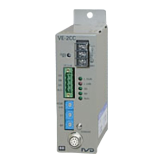
- Page 1 ZEF004410502 Specifications & Instruction Manual ABSOCODER CONVERTER FOR CC-Link Ver. 1.10 VE-2CC VM-2CC Applicable sensor: VRE-P028 VRE-P062 MRE-32SP062 MRE-G□SP062...
- Page 3 - Be sure to store the controller in designed temperature and humidity CAUTION range, and do not exposed to direct sunlight. - Be sure to consult with NSD when the controller is stored for long - Be sure to handle the controller as industrial waste while periods.
- Page 4 < VE-2CC / VM-2CC Specifications & Instruction Manual Revision History> * The Document No. appears at the upper right of this manual's cover page. Document No. Date Revision Description ZEF004410500 20, Mar., 2008 1st Edition Japanese document: ZEF004410206 ZEF004410501 3, Mar., 2014...
-
Page 5: Table Of Contents
CONTENTS 1. SUMMARY ................................1 1-1. Summary ................................1 1-2. Features ................................1 2. CONFIGURATION ..............................2 3. SPECIFICATIONS ..............................3 3-1. Converter Specifications ............................ 3 3-2. ABSOCODER and Extension Sensor Cable Specifications ................4 4. DIMENSIONS ................................6 4-1. Converter ................................6 4-2. -
Page 6: Summary
1. SUMMARY 1-1. Summary This manual describes the specifications and instruction procedures for the VE-2CC/VM-2CC which is able to connect to the open-architecture network "CC-Link". VE-2CC/VM-2CC is a converter which can detect the machine's current position value by ABSOCODER. The ABSOCODER sensor uses a magnetic position detection format, thereby the incremental format encoder which has been used can be replaced to VE-2CC/VM-2CC. -
Page 7: Configuration
④Servo-mount fixture -Cable: dedicated cable for CC-Link (Accessory) (commercially available cable) ③Extension sensor cable ⑤Reinforced servo-mount ⑥L type flange-mount fixture ②ABSOCODER fixture (Option) (Option) ●VE-2CC Name Model Note Converter VE-2CC ① ABSOCODER VRE-P062SAC Shaft shape: flat, servo-mount type ② φ62mm... -
Page 8: Specifications
Book-shelf type within enclosure Outside dimension (mm) 45(W)×160(H)×115(D) Refer to dimensions for details. Mass Approx. 0.7kg (2) Performance Specification Items Specifications Converter model VE-2CC VM-2CC Applicable sensor VRE-P028/062 MRE-32SP062, MRE-G□SP062 Position detection format Absolute position detection by ABSOCODER Number position... -
Page 9: Absocoder And Extension Sensor Cable Specifications
6-core, 2 pairs without shield + 1 pair with shield Color of sheath Gray Black Usable with moving machine Advantage Extensible for long distances member thanks to excellent flexibility [Remark] Contact your NSD representative when the extension cable is combined to use with different kinds of cables. - Page 10 8-core, 2 pairs without shield + 2 pairs with shield Color of sheath Gray Black Usable with moving machine Advantage Extensible for long distances member thanks to excellent flexibility [Remark] Contact your NSD representative when the extension cable is combined to use with different kinds of cables.
-
Page 11: Dimensions
4. DIMENSIONS 4-1. Converter ● VE-2CC Units: mm ● VM-2CC... -
Page 12: Absocoder Sensor
4-2. ABSOCODER Sensor (1) VRE-P028 Units: mm... - Page 13 Units: mm (2) VRE-P062...
- Page 14 Units: mm...
- Page 15 Units: mm (3) MRE-32SP062,MRE-G□SP062...
- Page 16 Units: mm...
-
Page 17: Extension Sensor Cable
4-3. Extension Sensor Cable ●3P-S-0102- L /3P-RBT-0102- L ●4P-S-0102- L /4P-RBT-0102- L Units: mm... -
Page 18: Installation And Precautions
5. INSTALLATION AND PRECAUTIONS 5-1. Converter Installation Conditions and Precautions The installation conditions and precautions for each of the system components are described in this section. - Installation Site (1) Avoid sites where the unit is exposed to direct sunlight. (2) The ambient temperature should never exceed a 0 to 55°C range. -
Page 19: Wiring
6. WIRING 6-1. Connection between Converter and ABSOCODER Sensor Converter ABSOCODER The cable connector is connected to the sensor connector of the converter. The ABSOCODER sensor is equipped with a 2-meter interconnecting sensor cable. If a longer length is required, dedicated extension sensor cable must be used. Extension sensor cable -Wiring Precautions (1) The sensor cable should be clamped as shown... -
Page 20: Cc-Link Connection
6-3. CC-Link Connection ●Connection configuration Power supply 24VDC VE-2CC VE-2CC VM-2CC Power CPU CC- Supply Link master Terminal resistor Terminal resistor ●Wiring - Use the dedicated cable for CC-Link. - Both sides of the unit of CC-Link must be connected with the terminal resistor. -
Page 21: Nomenclature And Function
7. NOMENCLATURE and FUNCTION 7-1. Part Identification and Function ① Terminal block of external power supply Connects to 24VDC and ground wire by the input terminal of the external power supply. ① ② ZERO SET button ② The position data is “0” (zero point setting) when pressing the button more than 1 second. -
Page 22: Zero Point Setting
7-2. Zero Point Setting “Zero point setting” is that the position data is designated on “0”. Zero point setting is proceeded by pressing ZERO SET button on the panel side after moving the machine position to the zero point. (1) Move the machine to the desired zero-point position. (2) Verify that a normal status exists at the converter (3) Hold “ZERO SET”... -
Page 23: Cc-Link Communication
Explains the communication contents of the “master station” and “remote station”. Master station: Controls the data link system of the programmable controller side. Remote station: VE-2CC, VM-2CC (remote device station) Following contents are available on the network: - Readout the position data... -
Page 24: Current Position Value Setting Data (Master To Remote Station)
8-2. Current Position Value Setting Data (Master to Remote Station) The master station can change the position data of VE-2CC/VM-2CC at arbitrary values by using the remote register (RWw) and remote output (RY). (Current position value setting) After setting, the remote station sends back the answer back signals by using remote inputs (RX). The master station turns off the signal after checking the bit. - Page 25 (1) Timing The current position value is set by writing the current position setting data (PRD0-PRD23) and PRESET signals from the master station. Current position setting data PRD0~PRD23 Link scan is more than one time PRESET signal PRESET ANSWER Current position Old current position New current position New current position updating...
- Page 26 MELSEC-Q series. The parameter should be set as right figure. Also, the station No. of VE-2CC / VM-2CC is set at 1 and 2. This is a program example when setting the current position for the station No.1 of VE-2CC / VM-2CC.
-
Page 27: Readout Errors
8-3. Readout Errors The error signal inputs to the master station as following contents by using remote input (RX). RX00 to 04 data is standard diagnosis data of VE-2CC/VM-2CC (remote station). Device No. RX07 RX06 RX05 RX04 RX03 RX02 RX01... -
Page 28: Setting Methods
9. SETTING METHODS 9-1. Setting and Procedure Before the Operation Explains usage procedures of ABSOCODER. START Converter mounting Mounting the converter (VE-2CC/VM-2CC). Connect with external device Connect ABSOCODER sensor and dedicated cable for CC-Link. Switch setting Set the station No. and communication speed setting switch. -
Page 29: Switch Setting
●Station No. setting switch Sets station No. of the converter. Setting range: 1 to 64 The occupied station number of VE-2CC / VM-2CC is 1. “LERR” LED will be ON if the number is set except 0 to 64. (Factory setting: 0) ●Communication speed setting switch... -
Page 30: Troubleshooting
10. TROUBLESHOOTING Explains the troubleshooting when using the VE-2CC/VM-2CC. Error occurs Is the communication cable Is “ERR “LED of connector disconnected? the master unit ON? Check the connection of the cable. Refer to "7-3. LED Display Contents”. Is “RUN “LED of VE/VM-2CC ON? Check the error state. -
Page 31: Flowchart When Having Error Signals
ABSOCODER Sensor. The causes are as follows: - Sensor cables are severed. - The internal circuit of VE-2CC/VM-2CC has a malfunction. - ABSOCODER has a malfunction. Contact your NSD representative. (2) Memory error Is “ME” LED ON? Does an error clear by the VE-2CC/VM-2CC has a malfunction. - Page 32 Manufacturer NSD Corporation 3-31-28, OSU, NAKA-KU, NAGOYA, JAPAN 460-8302 Distributor NSD Trading Corporation 3-31-23, OSU, NAKA-KU, NAGOYA, JAPAN 460-8302 Phone: +81-52-261-2352 Facsimile: +81-52-252-0522 URL: www.nsdcorp.com E-mail: foreign@nsdcorp.com Copyright©2020 NSD Corporation All rights reserved.
Need help?
Do you have a question about the VE-2CC and is the answer not in the manual?
Questions and answers