
Related Manuals for NSD MELSEC-Q VS-QA262B-L8


Summary of Contents for NSD MELSEC-Q VS-QA262B-L8
- Page 1 ZEF006083501 For Iron and Steel Industry MELSEC-Q PLC Module Converter VS-QA262B-L8 User’s Manual Applicable sensor: VLS-8SM...
-
Page 3: Table Of Contents
CONTENTS SAFETY PRECAUTIONS ..........................i INTRODUCTION ...............................iv TRADEMARKS ..............................iv REVISION HISTORY ............................v 1. OVERVIEW ........................1 1.1 Features ..............................3 1.2 Definitions ..............................3 2. SYSTEM CONFIGURATION ................... 5 2.1 Overall Configuration ..........................5 2.2 Applicable System ............................. 6 2.3 Function Block Diagram .......................... - Page 4 APPENDIX 3 KC MARK ....................37 APPENDIX 4 ABSOCODER SENSOR SPECIFICATIONS ..........39 Appendix 4.1 ABSOCODER Sensor for VS-QA262B-L8 ................39 Appendix 4.1.1 Specifications ........................39 Appendix 4.1.2 ABSOCODER Sensor Dimensions ................. 41 Appendix 4.2 ABSOCODER Cable ......................43 Appendix 4.2.1 Specifications ........................43 Appendix 4.2.2 Cable length restrictions ....................
-
Page 5: Safety Precautions
NSD. This product is designed to be used under the industrial environments categorized in Class A device. - Page 6 [ Installation Precautions ] CAUTION - Use the programmable controller in an environment that meets the general specifications contained in the CPU User's Manual. Failure to do so may result in electrical shock, fire, malfunction, product damage, or deterioration of performance.
- Page 7 [ Start-up and Maintenance Precautions ] WARNING - Be sure to shut off all power before cleaning this module or tightening screws. Failure to do so may result in failure or malfunction of this module. Loose screws can cause drops of the screws, short circuit or malfunction. Overt-tightening screws may damage the screws and/or the module, This can cause drops, short circuit or malfunction.
-
Page 8: Introduction
INTRODUCTION Thank you for purchasing the VS-QA262B module. Always read through this manual, and fully comprehend the functions and performance of VS-QA262B before starting use to ensure correct usage of this product. Please submit this manual to the end user. TRADEMARKS MELSEC is the trademark or registered trademark of Mitsubishi Electric Corporation. -
Page 9: Revision History
REVISION HISTORY The document No. appears at the upper right of this manual's cover page. Document No. Date Revision Description ZEF006083500 1st Edition 28, Jan., 2022 Japanese document: ZEF006081800 ZEF006083501 2nd Edition 26, Dec., 2022 Japanese document: ZEF006081801... -
Page 10: Overview
1. OVERVIEW 1. OVERVIEW This user's manual contains the specifications, and operation/programming procedures for VS-QA262B-L8 (*1) which is to be used in combination with a Mitsubishi Electric corp. MELSEC-Q Series programmable controller. VS-QA262B can detect the machine position by the combination with a linear type ABSOCODER sensor. - Page 11 Current Position Detection Function VS-QA262B's current position detection function detects the current position using an ABSOCODER sensor. Conventionally, this was detected using an incremental format encoder in conjunction with a counter unit. (1) Operation Example of System with Incremental Format Encoder and Counter Incremental format encoder...
-
Page 12: Features
1.2 Definitions (1) ABSOCODER ABSOCODER is the generic name given to the NSD-developed position sensor which detects rotational/linear displacement, speed, and acceleration, using an absolute position detection method with a digital (or analog) output. ABSOCODER consists of two main components:... - Page 13 (3) Semi-absolute format In the semi-absolute format, “standard pitch” of the sensor rod is detected in absolute value. (Absolute detection range) Furthermore, the pitch is counted by the software. 1 pitch 2 pitches 3 pitches Absolute detection pitch Absolute detection pitch Absolute detection pitch (8192) (8192)
-
Page 14: System Configuration
2. SYSTEM CONFIGURATION 2. SYSTEM CONFIGURATION 2.1 Overall Configuration The overall configuration of the Mitsubishi Electric corp. MELSEC-Q Series using VS-QA262B is shown below. Q××CPU I/O Module Main base unit(Q3[ ]B) Refer to the Remarks below. Extension cable(QC[ ]B) VS-QA262B ABSOCODER cable Extension base unit(Q6[ ]B) (see Appendix 4.) -
Page 15: Applicable System
VS-QA262B can be used in the following system. (1) Applicable CPU module Refer to NSD web site for CPU module models with which VS-QA262B can be used. (2) Number of mountable modules Pay attention to the power supply capacity before mounting modules. -
Page 16: Vs-Qa262B Specifications
3. VS-QA262B SPECIFICATIONS 3. VS-QA262B SPECIFICATIONS 3.1 General Specifications Shown below are the VS-QA262B specifications. About the ABSOCODER sensor specifications, refer to Appendix 4, "ABSOCODER SENSOR SPECIFICATIONS". Table 3.1 General Specifications Items Specifications Operating ambient temperature 0 to 55°C Storage ambient temperature -25 to 75°C Operating ambient humidity 5 to 95%RH... -
Page 17: Performance Specifications
3.2 Performance Specifications Table 3.2 Performance Specifications Items Specifications Remarks Number of position detection axes Position detection method Semi-absolute format 1μm(8.192mm/8192 divisions) Resolution Standard pitch x number of pitches Total number of divisions (8192 divisions (2 ) x max. 2048 pitches) - Current position detection function Function - Current position setting function... -
Page 18: Input/Output Signals Between Vs-Qa262B And Plc Cpu
3.4 Input/Output Signals between VS-QA262B and PLC CPU Below shows the input and output signals to the PLC CPU. (1) In the table below, the input/output signals are classified as follows: (a) Device X: Input signals from VS-QA262B to PLC CPU. (b) Device Y: Output signals from PLC CPU to VS-QA262B. -
Page 19: Input/Output Signal Details
3.4.1 Input/output signal details The ON/OFF timing and other conditions for signal input/output between VS-QA262B and PLC CPU are explained below. (1) Unit ready (X0): This signal comes OFF when a watchdog timer error is detected by VS-QA262B’s self-diagnosis function. When ‘X0’... - Page 20 (5) Error detection (X5 [X9]): This signal comes ON when any of the ‘X4 [X8]’ signal comes ON, or when any of the errors shown section 6.1 occur. ‘X5 [X9]’ will go OFF after the cause of the error has been corrected, and the ‘Y1C’ (error reset signal) has been turned ON by the sequence program.
-
Page 21: Buffer Memory
3.5 Buffer Memory VS-QA262B contains a buffer memory which is used for data communication with the PLC CPU. The buffer memory configuration and content is shown below. Data readout of all areas can be executed by the sequence program. Buffer memory space is provided for 2 axes (same content). Addresses 0 to 702 are for Axis 1, and addresses 1000 to 1702 are for Axis 2. -
Page 22: Current Position Value Storage Area
3.5.2 Current position value storage area The machine’s current position is detected by a semi-absolute method, and that position is stored in this area as a sensor binary value. Two data areas for the current position value, depending on the direction in which the current position value increases, are as follows: Current Position Value increasing in CW Direction (Address 2, 3 [1002, 1003]): The current position value will increase when the rod travels in the CW direction shown below. -
Page 23: Current Position Setting Value Storage Area
3.5.5 Current position setting value storage area This is the area where the setting value used for current position value setting by CPU output (Y13 [Y16]) is stored. (Address 690, 691 [1690, 1691]) This area can be written at any time by the sequence program. ‘0’... -
Page 24: Handling And Wiring
4. HANDLING and WIRING 4 HANDLING and WIRING This section explains how to unpack and connect VS-QA262B. 4.1 VS-QA262B Handling Precautions The following precautions should be observed when handling VS-QA262B. (1) As VS-QA262B is constructed from a resin-based material, it should not be dropped or subjected to severe shocks. -
Page 25: Wiring Precautions For Absocoder Cables
(3) When the cable port is exposed, a shielding plate Shielding plate should be installed as shown in the right figure. Contact your NSD representative for details of the installation conditions and precautions for ABSOCODER sensor. 4.3.2 Precautions for connecting ABSOCODER sensors (1) Connection should be made using the ABSOCODER cable, with the connector being securely tightened. -
Page 26: Name Of Parts
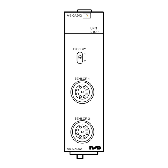
4.4 Name of Parts The illustration below shows the nomenclature of VS-QA262B. Operation status display area Axis display selection switch Sensor connector (Axis 1) Sensor connector (Axis 2) Functions of operation status display area Lower: "5" LED (Axis 1 Error LED) Upper: 0 to F LED Switches on or blinks when an Axis 1 lower: 0 to 4 LED... - Page 27 MEMO...
-
Page 28: Current Position Detection Function
5. CURRENT POSITION DETECTION FUNCTION 5. CURRENT POSITION DETECTION FUNCTION 5.1 Function Description 5.1.1 Current position detection function VS-QA262B's current position detection function detects the current position using an ABSOCODER sensor. Conventionally, this was detected using an incremental format encoder in conjunction with a counter unit. -
Page 29: Current Position Setting Function
5.1.2 Current position setting function "Current position setting" is a function to change VS-QA262B's current position value to a value corresponding to the current and actual machine position. The Current Position Value in CW Direction (Address 2, 3 [1002, 1003]) or the Current Position Value in CCW Direction (Address 4, 5 [1004, 1005]) in buffer memory will be changed to a pre-entered Current Position Setting Value (Address 690, 691 [1690, 1691]). - Page 30 Current position setting timing Writing by TO instruction ▼ Buffer memory Previous current Current position setting value New current position value position value (Address 690, 691 [1690 ,1691]) Current position setting Command (Device Y13 [Y16]) Buffer memory Current position value in CW direction (Address 2, 3 [1002, 1003]) Previous current...
-
Page 31: Pre-Operation Setting Sequence
5.2 Pre-Operation Setting Sequence This section explains the setting sequence for the current position detection function. Start Installation on base unit: Install VS-QA262B on the base unit. External connections: Refer to Section 4.2 and 4.3. Connect the ABSOCODER sensor to VS-QA262B. Programming: Create a sequence program to read out the current position... -
Page 32: Programming
5.3 Programming This section explains how to create the sequence program using VS-QA262B. 5.3.1 Program creation precautions (1) VS-QA262B is an intelligent function module that occupies thirty two I/O points. (2) In response to ‘FROM/TO’ instructions, the first input/output No. of VS-QA262B’s slot will be designated. -
Page 33: Program For Current Position Monitor Display
5.3.2 Program for current position monitor display A program example for the current position monitor display is given below. This program example is for Axis 1. Axis 2 programs can be generated in the same way. Conditions The following signal assignments are used to control VS-QA262B. VS-QA262B ‘online’... -
Page 34: Program For Error Code Readout And Reset
5.3.3 Program for error code readout and reset A program example for the error code readout and error reset operation which is used when a VS-QA262B 'error detection' occurs is given below. This program example is for Axis 1. Axis 2 programs can be generated in the same way. Conditions The following signal assignments are used to control VS-QA262B. - Page 35 (2) Example of program using an intelligent function device (U[ ]¥G[ ]). │ X0032 │ 0├─┤ ├──────────────────────────────────────────────────────────────(Y0010 )┤ │ VS-QA262B PLC read │ │ ‘onli │ │ ne’ com │ │ mand │ │ │ │ X0001 X0004 │ Sensor error monitor output 2├─┤...
-
Page 36: Remote I/O Station Programming
5.3.4 Remote I/O station programming The master station (CPU) programming which is required when VS-QA262B is installed in a remote station is explained below. This program example is for Axis 1. Axis 2 programs can be generated in the same way. (1)System configuration Remote master station (Station No.0) QCPU... - Page 37 (2) Program example │ SB0047 │ 0├─┤ ├────────────────────────────────────────────────────────(T0 )┤ │ Host bat 1ms time │ │ on pass │ │ status │ │ │ │ │ │ SB0049 │ 5├─┤ ├────────────────────────────────────────────────────────(T1 )┤ │ Host dat 1ms time │ │ a link s │...
-
Page 38: Troubleshooting
6. TROUBLESHOOTING 6. TROUBLESHOOTING VS-QA262B operation errors and troubleshooting procedures are described in this section. 6.1 Error Code List VS-QA262B error codes are described below. When VS-QA262B detects an error, the corresponding error code is stored in Address 7 [1007] of the buffer memory. - Page 39 (1) Each time an error occurs, the previous error code stored in the buffer memory will be deleted, and replaced by the new error code. (2) The error status will be automatically cleared when the PLC CPU reset status is canceled. (3) The error code stored in the buffer memory will not be cleared (returned to '0') simply by correcting the cause of the error.
-
Page 40: Troubleshooting Flowchart
6.2 Troubleshooting Flowchart The VS-QA262B troubleshooting procedure is explained below. For CPU module related problems, consult the manual for the CPU module in question. Error Occurs If the signal doesn’t go ON even when the PLC CPU is reset, a VS-QA262B hardware problem is likely. -
Page 41: Flowchart When Current Position Setting Is Impossible
6.3 Flowchart when Current Position Setting is Impossible Current position setting can not be executed. Note the error code, and Does an error status check the causes. exist at VS-QA262B? ‘Online’ status Designate the ‘online’ status. established? Turn Y13 [Y16] ON Current Position Setting Is Y13 [Y16] turned ON Command Y13 [Y16] will be... -
Page 42: Flowchart When The Absocoder Sensor's Current Position Value Doesn't Change
6.4 Flowchart when the ABSOCODER Sensor’s Current Position Value doesn't Change The ABSOCODER sensor’s current position value doesn’t change. Does an error status Note the error code, and check the exist at VS-QA262B? causes. Does the ABSOCODER Travel the ABSOCODER sensor. sensor travel? Refer to Section 4.2 and Appendix Is the ABSOCODER... - Page 43 MEMO...
-
Page 44: Appendix 1 Ce Marking
APPENDIX APPENDIX 1 CE MARKING VS-QA262B series conforms to EMC directive, but stands outside scope of the low voltage directive. (1) EMC Directives It is necessary to do CE marking in the customer’s responsibility in the state of a final product. Confirm EMC compliance of the machine and the entire device by customer because EMC changes configuration of the control panel, wiring, and layout. -
Page 45: Appendix 2 Ul Standard
APPENDIX 2 UL STANDARD The VS-QA262B Series corresponds to the UL standard. Read this page carefully and use the VS-QA262B Series by following the described items. (1) Installation - Install inside the control cabinet. - For use in pollution degree 2 environment. - Within the surrounding air temperature 0℃... -
Page 46: Appendix 3 Kc Mark
APPENDIX 3 KC MARK Notification for users 사용자안내문 This product complied with the relevant Korean Safety Standard for use in the industrial environment. Thus, radio frequency interference could occur if it is used in a domestic environment. 이 기기는 업무용 환경에서 사용할 목적으로 적합성평가를 받은 기기로서 가정용... - Page 47 MEMO...
-
Page 48: Appendix 4 Absocoder Sensor Specifications
APPENDIX 4 ABSOCODER SENSOR SPECIFICATIONS Appendix 4.1 ABSOCODER Sensor for VS-QA262B-L8 Appendix 4.1.1 Specifications (1) VLS-8SM20 Items Specifications Model VLS-8SM20 Max. detection stroke 350 mm Absolute detection range 8.192 mm Resolution 1μm(8.192mm/8192) Linearity error Customer's Special Specifications Head 4.5+0.15 x [cable length(m)] kg Mass 0.4+0.0025 x [stroke (mm)] kg Sliding resistance... - Page 49 (2) VLS-8SM14, VLS-8SM14S Items Specifications Model VLS-8SM14 VLS-8SM14S Max. detection stroke 200 mm Absolute detection range 8.192 mm Resolution 1μm(8.192mm/8192) Linearity error Customer's Special Specifications Head 1.1+0.07 x [cable length(m)] kg 0.8+0.07 x [cable length(m)] kg Mass 0.0012 x ([rod length (mm)] kg Sliding resistance 15 N or less (1.5kgf or less) Permissible mechanical speed...
-
Page 50: Appendix 4.1.2 Absocoder Sensor Dimensions
Appendix 4.1.2 ABSOCODER Sensor Dimensions (1) VLS-8SM20-[ ]FA[ ] (Flange-mount type) Units: mm (2) VLS-8SM20-[ ]LA[ ] (Base-mount type) - Page 51 (3) VLS-8SM14-[ ]FB[ ] (Flange-mount type) Units: mm (4) VLS-8SM14S-[ ]LB[ ] (Flange-mount type)
-
Page 52: Appendix 4.2 Absocoder Cable
The maximum cable lengths for each ABSOCODER sensor model are shown below. Sensor cable model 3S-S 3S-RBT 3S-URT 3S-HRT Sensor model VLS-8SM20 VLS-8SM14 200m 100m 100m 100m VLS-8SM14S REMARKS Contact your NSD representative when the ABSOCODER cable combines different types of cables. -
Page 53: Appendix 4.2.3 Absocoder Cable Dimensions
Appendix 4.2.3 ABSOCODER Cable Dimensions (1) 3S-S-0144-[L] / 3S-RBT-0144-[L] / 3S-URT-0144-[L] Units: mm NOTE: [L] is given in terms of meter. (2) 3S-S-4344-[L] / 3S-RBT-4344-[L] / 3S-URT-4344-[L] NOTE: [L] is given in terms of meter. (3) 3S-HRT-5152-[L] NOTE: [L] is given in terms of meter. (4) 3S-S-0190-[L] / 3S-RBT-0190-[L] / 3S-URT-0190-[L] NOTE: [L] is given in terms of meter. - Page 54 (5) 3S-S-9044-[L] / 3S-RBT-9044-[L] / 3S-URT-9044-[L] Units: mm NOTE: [L] is given in terms of meter. (6) 3S-HRT-9052-[L] NOTE: [L] is given in terms of meter. (7) 3S-S-9090-[L] / 3S-RBT-9090-[L] / 3S-URT-9090-[L] NOTE: [L] is given in terms of meter. (8) 3S-HRT-9090-[L] NOTE: [L] is given in terms of meter.
-
Page 55: Appendix 4.2.4 Absocoder Cable Connection
Appendix 4.2.4 ABSOCODER Cable Connection Indicates the ABSOCODER sensor cable connection example when connecting by the standard connector or the crimping terminal. ● In the case of connecting by using connectors VS-QA262B Extension sensor cable ABSOCODER sensor... - Page 56 Extension sensor cable VS-QA262B Crimping Crimping Crimping terminal (R1.25-4) terminal terminal (R1.25-4) (R1.25-4) ABSOCODER sensor NSD special cable NSD special cable Wire color Wire color Wire color Wire color Signal name Wire color Signal name Wire color Signal name Brown Brown...
-
Page 57: Appendix 5 Dimensions
APPENDIX 5 DIMENSIONS Appendix 5.1 VS-QA262B Position Detection Module Units: mm... -
Page 58: Appendix 6 Absocoder Sensor Check List
APPENDIX 6 ABSOCODER SENSOR CHECK LIST ● Applicable ABSOCODER sensor models VLS-8SM20 VLS-8SM14 VLS-8SM14S ● Connection configuration VS-QA262B ABSOCODER sensor Extension sensor cable ● Connector appearance and pin position View View A1, B1 ● Connector pin position and standard coil resistance ranges (at 25℃) Check position Standard coil resistance [Ω] A1, A2, B1, B2... - Page 59 *1: If checks are done at Point B, the measurement value is [Standard coil resistance + extension sensor cable resistance]. Extension sensor cable resistance value The resistance value of the NSD special cable is 0.2Ω/m (loop resistance). Consider resistance variations due to temperature, which, relative to the standard temperature (25 C), increases 0.4% when the temperature rises 1...
-
Page 60: Appendix 7 I/O Signals And Buffer Memory Function List
APPENDIX 7 I/O SIGNALS and BUFFER MEMORY FUNCTION LIST ◯: enabled ×: disabled Signal VS-QA262B (online/offline) Online Offline Remarks type Device No., address, and name Unit ready ○ ○ (VS-QA262B detection item) VS-QA262B operation status (online/offline) Signal Signal during the operation inputs to ○... - Page 62 Manufacturer NSD Corporation 3-31-28, OSU, NAKA-KU, NAGOYA, JAPAN 460-8302 Distributor NSD Trading Corporation 3-31-23, OSU, NAKA-KU, NAGOYA, JAPAN 460-8302 Phone: +81-52-261-2352 Facsimile: +81-52-252-0522 URL: www.nsdcorp.com E-mail: foreign@nsdcorp.com Copyright©2023 NSD Corporation All rights reserved.
Need help?
Do you have a question about the MELSEC-Q VS-QA262B-L8 and is the answer not in the manual?
Questions and answers