
Related Manuals for NSD MELSEC-Q VS-QA262-M2PG


Summary of Contents for NSD MELSEC-Q VS-QA262-M2PG
- Page 1 ZEF006082701 MELSEC-Q PLC Module Converter VS-QA262-M2PG User’s Manual Applicable sensor: MRE-32SP062 MRE-G[ ]SP062...
-
Page 3: Table Of Contents
CONTENTS SAFETY PRECAUTIONS ..........................i INTRODUCTION ............................iv TRADEMARKS ............................. iv REVISION HISTORY ............................. v 1. OVERVIEW ........................1 1.1 Features ..............................5 1.2 Definitions..............................6 2. SYSTEM CONFIGURATION ..................9 2.1 Overall Configuration ..........................9 2.2 Applicable System ..........................10 2.3 Function Block Diagram ......................... - Page 4 5. CURRENT POSITION DETECTION FUNCTION ............43 5.1 Function Description ..........................43 5.1.1 Current position detection function ....................43 5.1.2 Current position 'PRESET' function ....................44 5.2 Pre-Operation Setting Sequence ......................47 5.3 Initial setting ............................48 5.3.1 Initial setting list ..........................48 5.3.2 Sensor rotation direction setting ......................
- Page 5 7. POSITIONING FUNCTION ................... 93 7.1 Function Description ..........................93 7.1.1 Unidirectional positioning ........................ 95 7.1.2 Positioning by speed switching format .................... 96 7.1.3 Positioning by speed stepping format ..................... 97 7.1.4 Control timing ..........................98 7.1.5 Starting operation from stop zone ....................100 7.1.6 Simple learning function ........................
- Page 6 Appendix 4.2.3 ABSOCODER Cable Dimensions ................. 140 Appendix 4.2.4 ABSOCODER Cable Connection .................. 141 APPENDIX 5 DIMENSIONS ................... 142 Appendix 5.1 VS-QA262 ..........................142 APPENDIX 6 ABSOCODER SENSOR CHECK LIST ............ 143 APPENDIX 7 I/O SIGNALS and BUFFER MEMORY FUNCTION LIST ......145 APPENDIX 8 DATA SHEET ...................
-
Page 7: Safety Precautions
NSD. This product is designed to be used under the industrial environments categorized in Class A device. - Page 8 [ Installation Precautions ] CAUTION - Use the programmable controller in an environment that meets the general specifications contained in the CPU User's Manual. Failure to do so may result in electrical shock, fire, malfunction, product damage, or deterioration of performance.
- Page 9 [ Start-up and Maintenance Precautions ] WARNING - Be sure to shut off all power before cleaning this module or tightening screws. Failure to do so may result in failure or malfunction of this module. Loose screws can cause drops of the screws, short circuit or malfunction. Overt-tightening screws may damage the screws and/or the module, This can cause drops, short circuit or malfunction.
-
Page 10: Introduction
INTRODUCTION Thank you for purchasing the VS-QA262 module. Always read through this manual, and fully comprehend the functions and performance of VS-QA262 before starting use to ensure correct usage of this product. Please submit this manual to the end user. TRADEMARKS MELSEC is the trademark or registered trademark of Mitsubishi Electric Corporation. -
Page 11: Revision History
REVISION HISTORY The document No. appears at the upper right of this manual's cover page. Document No. Date Revision Description ZEF006082700 28, Jan., 2022 1st Edition Japanese document: ZEF006081000 ZEF006082701 26, Dec., 2022 2nd Edition Japanese document: ZEF006081001... -
Page 12: Overview
1. OVERVIEW 1. OVERVIEW VS-QA262 is a built-in module for the MELSEC-Q Series PLC made by MITSUBISHI ELECTRONIC CORPORATION. Combination of VS-QA262 with two ABSOCODER sensors makes the biaxial positioning control possible. The ABSOCODER sensor is a magnetic position sensor which can replace incremental type encoders which have been widely used until now. - Page 13 Current Position Detection Function VS-QA262's current position detection function detects the current position using an ABSOCODER sensor. Conventionally, this was detected using an incremental format encoder in conjunction with a counter unit. The above conventional method has several disadvantages; origin-point return is necessary when power supply is interrupted due to power failure, etc.
- Page 14 Limit SW output Function The VS-QA262 limit SW output function differs from that of other systems. The limit switch position data is pre-designated at VS-QA262, without the need for limit switches. The ABSOCODER sensor detects the machine's travel amount and ON/OFF signal outputs occur when the machine's position matches pre-designated positions.
- Page 15 Positioning Function All positioning data such as the target stop positions and speed switching positions, etc., are pre-designated at VS-QA262. The ABSOCODER sensor then detects the machine's travel amount, with the appropriate speed switching or STOP signals being output when the machine's position matches the pre-designated position. With this positioning function, the following two output formats for positioning signals can be used.
-
Page 16: Features
1.1 Features VS-QA262 has the following features: (1) Absolute position detection: Rotational position is detected by an absolute position detection method. Even when a power outage, etc., occurs, the correct position of the ABSOCODER sensor will be instantly detected when power is turned back ON. (2) Able to handle two sensors: Two ABSOCODER sensors can be connected. -
Page 17: Definitions
1.2 Definitions (1) ABSOCODER ABSOCODER is the generic name given to the NSD-developed position sensor which detects rotational/linear displacement, speed, and acceleration, using an absolute position detection method with a digital (or analog) output. The ABSOCODER sensor consists of two main components:... - Page 18 (4) Minimum Current Position value This is the minimum value of the scale length which can be displayed. This value can be designated as desired within the following range: -99999 to [1000000-scale length]. <Example> Given the same conditions as those described in the 'Scale length' item above, and with the actual minimum position of the machine detection range being -10 mm, the following will apply: Actual minimum position -10...
- Page 19 (6) Unidirectional Positioning Positioning toward the target stop position is always executed from a single direction. When positioning is required in the opposite direction, the target stop position will be overshot, and positioning will then occur from the prescribed direction (U-turn is made). The unidirectional positioning format is useful in reducing stop position errors caused by backlash.
-
Page 20: System Configuration
2. SYSTEM CONFIGURATION 2. SYSTEM CONFIGURATION 2.1 Overall Configuration The overall configuration of the Mitsubishi Electric corp. MELSEC-Q Series using VS-QA262 is shown below. Q××CPU I/O Module Main base unit(Q3[ ]B) QYxx Refer to the Remarks below. Extension cable(QC[ ]B) VS-QA262 ABSOCODER cable Extension base unit(Q6[ ]B) -
Page 21: Applicable System
VS-QA262 can be used in the following system. (1) Applicable CPU module Refer to NSD web site for CPU module models with which VS-QA262 can be used. (2) Number of mountable modules Pay attention to the power supply capacity before mounting modules. -
Page 22: Vs-Qa262 Specifications
3. VS-QA262 SPECIFICATIONS 3. VS-QA262 SPECIFICATIONS 3.1 General Specifications Shown below are the VS-QA262 specifications. About the ABSOCODER sensor specifications, refer to Appendix 4, ‘ABSOCODER SENSOR SPECIFICATIONS’. Table 3.1 General Specifications Items Specifications Operating ambient temperature 0 to 55°C Storage ambient temperature -25 to 75°C Operating ambient humidity 5 to 95%RH... -
Page 23: Performance Specifications
3.2 Performance Specifications Table 3.2 Performance Specifications Items Specifications Remarks Number of position detection axes Position detection method Absolute position detection by ABSOCODER sensors [4096 divisions×32 turns] to Refer to Appendix 4 for Number of divisions [409.6 divisions×320 turns] details. Program No. -
Page 24: Function List
3.3 Function List As shown in table 3.3, VS-QA262’s functions are divided into two groups consisting of ‘main functions’ and ‘auxiliary functions’. The main functions of VS-QA262 are useful for actual system control, and the auxiliary functions are to support the main function operations. Table 3.3 Function List Function Description... - Page 25 Function Description Reference This function monitors the current position detected by ABSOCODER sensor to determine whether it has exceeded the upper limit value (upper limit of travel range) that was designated by the parameter. 'Upper limit overtravel' Section When the upper limit has been exceeded, the following errors detection function 7.4.7 will occur:...
-
Page 26: Input/Output Signals Between Vs-Qa262 And Plc Cpu
3.4 Input/Output Signals between VS-QA262 and PLC CPU Below shows the input and output signals to the PLC CPU. (1) Input/output signals between VS-QA262 and the PLC CPU are executed according to the following format: Input: 32 points Output: 32 points (2) In the table below, the input/output signals are classified as follows: (a) Device X: Input signals from VS-QA262 to the PLC CPU. -
Page 27: Input/Output Signal Details
3.4.1 Input/output signal details The ON/OFF timing and other conditions for signal input/output between VS-QA262 and the PLC CPU are explained below. (1) Unit ready (X0): This signal comes OFF when a watchdog timer error is detected by VS-QA262’s self-diagnosis function. - Page 28 (4) ‘Lower limit overtravel' detection (X3 [X7]): This signal turns ON when the current position value falls below the lower limit value designated by the parameter. At this time, VS-QA262’s positioning function and limit switch functions continue the respective works. Lower limit overtravel is detected only during an 'online' status.
- Page 29 (7) 'Excessive current position change' detection (XB [XE]): This signal turns ON in case any change amount of the current position value (scaling binary) for 20ms exceeds the ‘permissible current position change amount' designated by the parameter. Even when XB [XE] turns on, positioning and limit switch functions continue the respective works. When Y1C (error reset signal) is turned ON by the sequence program, XB [XE] goes OFF.
- Page 30 (10) ‘PLC ready' signal (Y10): This signal is used to switch the VS-QA262 operation status (online/offline). Y10 ON: Online Y10 OFF: Offline REMARKS The difference between the 'online' and 'offline' status is shown below. Online Offline PLC ready (Y10) ON PLC ready (Y10) OFF Online (X1) ON Online (X1) OFF...
- Page 31 (11) 'Positioning START' signal (Y11 [Y14]): This signal starts the positioning operation. The positioning operation signals will go ON when the following conditions are established: - Online status - Y12 [Y15] (positioning STOP signal) is OFF. - Y11 [Y14] is turned ON by the sequence program. Positioning will begin when the leading edge of Y11 [Y14] is detected.
- Page 32 (16) 'Error reset' signal (Y1C): The following operation error signals will be reset after the cause of the error has been corrected, and the ‘Y1C’ (error reset signal) has been turned ON by the sequence program. X2 [X6] ('Upper limit overtravel' detection) X3 [X7] ('Lower limit overtravel' detection) X4 [X8] (Sensor error detection) XA [XD] ('Excessive correction amount' detection)
-
Page 33: Buffer Memory
3.5 Buffer Memory VS-QA262 contains a buffer memory which is used for data communication with the PLC CPU. The buffer memory configuration and content are shown below. Data readout of all areas can be executed by the sequence program. Address (decimal) [ ]: Address for axis 2 Writing conditions by sequence program 0[1000] Current position value (scaling binary) - Page 34 Address (decimal) [ ]: Address for axis 2 Writing conditions by sequence program 668[1668] Speed output 669[1669] 670[1670] Hold current position (scaling binary) 671[1671] 672[1672] Hold current position (sensor binary) Writing disabled 673[1673] 674[1674] FWD stop zone after learning 675[1675] 676[1676] RVS stop zone after learning 677[1677]...
- Page 35 Address (decimal) [ ]: Address for axis 2 Writing conditions by sequence program 700[-] Data memory flag Writing enabled 701[-] Data memory flag answerback Writing disabled 702[1702] Sensor rotation direction (Initial setting) 703[1703] Not used 704[1704] Writing enabled at any time Scale length 705[1705] 706[1706] Not used...
-
Page 36: Current Position Value (Sensor Binary)' Storage Area
3.5.1 'Current position value (sensor binary)' storage area The machine's current position within the scale length is detected by the ABSOCODER sensor, and that position value is stored in this area as a 'sensor binary value'. The ranges for sensor binary current position values are as follows: Multi-turn type MRE: 0 to 131071 (0 to 1FFFFH). -
Page 37: I/O Status Storage Area
3.5.5 I/O status storage area This area is used to store the I/O status. (a) Current position preset command input status (b) Limit SW output status (ON/OFF status) (c) Positioning output status The I/O statuses are stored as follows: B8 B7 B6 B5 Address 6 [1006] 0 0 0 0 0 0 Current position preset command 1... -
Page 38: Limit Sw Output Disabled Setting' Area
3.5.7 'Limit SW output disabled setting' area The settings made at this area determine for each channel whether or not limit SW outputs are to occur. Although this area can be written to at any time by the sequence program, the settings are only operative when online status is established. -
Page 39: Program No. Setting Area
3.5.8 Program No. setting area This is the area where the program Nos. (total of 9) to be used for the limit SW output function are designated. This area can be written to at any time by the sequence program. (1) Settings are made by designating the program No. -
Page 40: Limit Sw Output On/Off Data Setting Area
3.5.10 Limit SW output ON/OFF data setting area The ON/OFF data used for the limit SW output function is stored at this area. (1) The data setting must be designated for each channel, and consists of the 'number of multi-dogs', and the ON/OFF position data for each dog. - Page 41 ② 'OFF Area' [Limit SW 'open (b) contact' operation] Dog Position Writing: The 'OFF area' should be written by a pair of the ON position data and the OFF position data. At this time, the ON position data should be larger than the OFF position data. When the numerical values for each dog are not written in order, beginning from the lowest and proceeding to the highest, an error will occur.
-
Page 42: Speed Output Storage Area
3.5.11 Speed output storage area This is the area where the rotation speed of the ABSOCODER sensor is stored. The stored speed value is two kinds; ‘amounts of the sensor binary value change’ and ‘r/min unit’. Selects either ‘amounts of the sensor binary value change’ or ‘r/min unit’ by using the 'speed gate time' (address 749 [1749]). -
Page 43: Hold Current Position Storage Area
3.5.12 Hold current position storage area This is the area where the current position value is stored when 'current position preset command' 1 or 2 is turned ON (detected at leading edge). The scaling binary value and the sensor binary value are stored. When the 'current position preset' function is active, the current position value before preset is stored. -
Page 44: Positioning Pattern Data Buffer Memory Selection Area
3.5.15 Positioning pattern data buffer memory selection area This is the area where the pattern data used for positioning is selected to via buffer memory (addresses 680 [1680] to 689 [1689]) or parameter setting (addresses 716 [1716] to 723 [1723]). When selected to via buffer memory, the data can be changed by the PLC CPU even while online. -
Page 45: Fwd/Rvs Stop Zone Setting Area
3.5.18 FWD/RVS stop zone setting area This is the area where the stop zone used for positioning by the speed stepping format or the speed switching format is set. This area can be written to at any time by the sequence program. The setting applies only when '1' is set to Bit 2 or 3 of the positioning pattern data buffer memory selection area (address 679 [1679]) and then the positioning START signal (Y11 [Y14]) is turned ON while online. -
Page 46: Current Position Preset Command Disabled Setting Area
3.5.21 Current position preset command disabled setting area When the parameter format or the buffer memory format is selected for the current position preset function, this area determins whether the curent position value is to be preset or not. This area can be written to at any time by the sequence program. '0' is automatically stored as a default when the PLC CPU is reset or the PLC power supply is turned OFF. -
Page 47: Data Memory Flag Answerback Area
3.5.23 Data memory flag answerback area This is the area where the flag selected at the ‘data memory flag area’ is stored. B4 B3 B2 B1 B0 Address 701 [-] Writing selection Program (PRGM) Parameter (PRM) Initial setting (INIT) When writing/reading is completed, ‘1’ is stored at the corresponding bit of the data memory flag. ‘0’... -
Page 48: Handling And Wiring
4. HANDLING and WIRING 4 HANDLING and WIRING This section explains how to unpack and connect VS-QA262. 4.1 VS-QA262 Handling Precautions The following precautions should be observed when handling VS-QA262. (1) As VS-QA262 is constructed from a resin-based material, it should not be dropped or subjected to severe shocks. -
Page 49: Precautions For Wiring Absocoder Cables
4.2 Precautions for Wiring ABSOCODER Cables The wiring precautions for the ABSOCODER cable are explained in this section. (1) The ABSOCODER cable should be located as far as possible from power lines and other lines which generate a high level electrical noise. (2) If location near the above power lines is unavoidable, the cable duct should be separated, with individual wiring conduits being provided. - Page 50 ● Mounting of Turn-type ABSOCODER sensor Item Explanation Precaution A ‘direct-link’ format will 1) Coupling of machine result in shaft fatigue shaft and sensor and / or breakage after shaft long periods. Therefore, be sure to use a coupling device to link the shafts.
-
Page 51: Precautions For Connecting Absocoder Sensors
● Coupling of Turn-type ABSOCODER sensor Item Explanation Precaution 1. Selection of the coupling device should be based on 1) Coupling device The selection of a selection precaution the following factors; larger coupling than - The amount of a mounting error caused by the necessary will machine design. -
Page 52: Name Of Parts
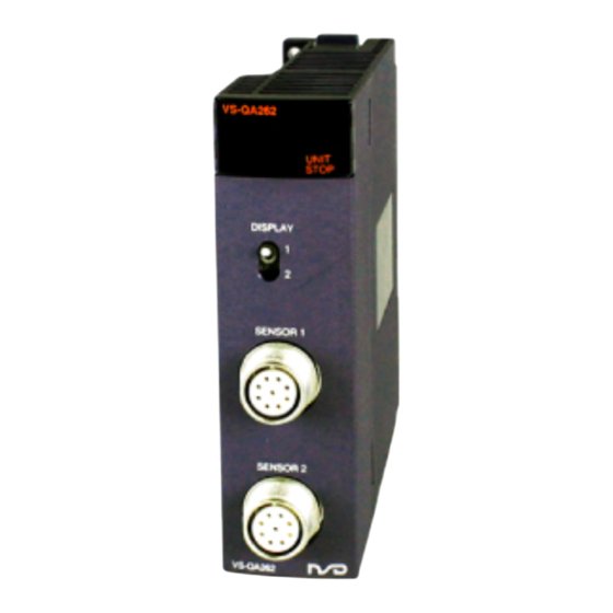
4.4 Name of Parts The illustration below shows the nomenclature of VS-QA262. Operation status display area Axis display selection switch Sensor connector (Axis 1) Sensor connector (Axis 2) Functions of operation status display area At the operation status display Output status display area area, the axis to display can be Current Limit... - Page 53 MEMO...
-
Page 54: Current Position Detection Function
5. CURRENT POSITION DETECTION FUNCTION 5. CURRENT POSITION DETECTION FUNCTION 5.1 Function Description This section explains VS-QA262's current position detection function. 5.1.1 Current position detection function ABSOCODER sensor VS-QA262's current position detection function detects the current position using an ABSOCODER Motor sensor. -
Page 55: Current Position 'Preset' Function
5.1.2 Current position 'PRESET' function This section explains VS-QA262's current position ‘preset’ function. When the current position 'preset' function is executed, the machine's ‘current position' will be set (corrected) to the 'preset position’ which has been designated in advance. This function is used when a misalignment occurs between the detected position and the actual machine position, as shown below. - Page 56 (4) The current position preset commands is commonly used for the current position hold function. (5) For the parameter format, the automatic travel direction determination by VS-QA262 is made by successively comparing the current position values at a 100 ms interval. However, when the reverse speed is below the levels shown in the following table, VS-QA262 will determine that the current travel is in forward direction.
- Page 57 (13) Current position preset timing Writing by TO instruction Buffer memory ▼ Current position preset value 1, 2 Previous setting value New setting value (690, 691 [1690, 1691], 692, 693 [1692, 1693] ) Current position preset command (Device Y13 [Y16], Y1E [Y1F] ) Buffer memory Current position value (scaling binary) Previous current...
-
Page 58: Pre-Operation Setting Sequence
5.2 Pre-Operation Setting Sequence This section explains setting sequences for the current position detection function. Start Installation on base units: Install VS-QA262 on the base unit. External connections: Connect the ABSOCODER sensor Refer to section 4.2 and 4.3. to VS-QA262. Current position unit conversion and origin-point setting (Not executed) -
Page 59: Initial Setting
5.3 Initial setting This section explains VS-QA262's initial settings. Initial setting values are factory-set (default). Designate only the initial setting item which is required to change. To enter settings, specify ’1’ at the relevant bit of the buffer memory's data memory flag (address 700 [-]). The initial settings of axes 1 and 2 are executed simultaneously. -
Page 60: Scale Length And Minimum Current Position Value Setting
5.3.3 Scale length and minimum current position value setting This section explains how to set scale lengths (addresses 704 [1704] to 705 [1705]) and the minimum current position value (addresses 707 [1707] to 708 [1708]). Only the scale length or the minimum current position value can be set. Refer to section 1.2 for definitions of the scale length and the minimum current position value. -
Page 61: Current Position Setting
5.3.4 Current position setting This section explains how to set the current position values (addresses 709 [1709] to 710 [1710]). The 'current position' setting consists of designating a numeric value which corresponds to a given machine position. For example, when the machine is moved to its 100 mm position, the 'current position' setting which corresponds to that position would be designated as '10000' (when resolution is 0.01). -
Page 62: Current Position Setting Sequence
5.3.6 Current position setting sequence (a) Move the machine to the desired setting position. (b) Turn the ’PLC ready’ signal (Y10) OFF. (c) Write the setting data to the buffer memory addresses 709 [1709] (L) and 710 [1710] (H). (At this time, the current position setting is not yet completed.) (d) Write ‘1’... -
Page 63: Parameter Settings
5.4 Parameter settings This section explains the parameters active for VS-QA262's current position detection function. Parameters are factory-set (default). Designate only the parameter item which is required to change. When default values are acceptable, it is not necessary to specify settings. When writing the parameters, specify ’1’... -
Page 64: Parameter List
5.4.1 Parameter list [ ]: Address for axis 2 Default Address Item Content Setting data 0: Limit SW output function & Designates 'Current position detection function positioning function only', 'limit SW output function only' or limit SW 711 [1711] Function 1: Limit SW output function only output function &... -
Page 65: Function Setting
5.4.2 Function setting This section explains how to set functions. VS-QA262 consists of 3 functions: The 'current position detection function', the 'limit SW output function', and the 'positioning function'. The function which is to be used is designated by 'function' parameter settings. The function selections are as follows: 0: For both the 'limit SW output function' and the 'positioning function' (X10 to 17 [X18 to 1F] outputs are used for the positioning function.) -
Page 66: Current Position Preset Function Setting
5.4.5 Current position preset function setting This section explains how to set the current position preset function. This setting determines whether or not to execute the current position preset, and the method if executing it. 0: Disabled 1: By the parameter format 2: By the buffer memory format 3: By the sequence format The current position preset function is set to buffer memory address 740 [1740]. -
Page 67: Speed Gate Time And Speed Sampling Time Setting
5.4.7 Speed gate time and speed sampling time setting This section explains how to set the speed gate time and the speed sampling time. This setting determines the measurement conditions of the data stored in the speed output area of the buffer memory addresses 668 [1668] (L) and 669 [1699] (H). -
Page 68: Programming
5.5 Programming This section explains how to create the sequence program using VS-QA262. 5.5.1 Program creation precautions (1) VS-QA262 is an intelligent function module that occupies thirty two I/O points. (2) In response to ‘FROM/TO’ instructions, the first input/output No. of VS-QA262’s slot will be designated. FROM H0 QA262 First input/output No. -
Page 69: Initial Setting And Parameter Setting Data Write Program
5.5.2 Initial setting and parameter setting data write program A program example for writing the initial setting and the parameter data to the VS-QA262 buffer memory is given below. Writing of the initial setting and parameter data for both axes is executed simultaneously. However, the individual current position setting is also possible. - Page 70 Program Example (1) Examples of programs using the FROM/TO instructions │ X0020 │ The PLC ready signal of VS-QA262 0├─┤ ├───┤/├───┤/├──────────────────────────────────────────────────(Y0010 )┤ │ VS-QA262 Initial Interloc PLC read │ is turned ON. │ online c setting │ │ ommand write as │...
- Page 71 (2) Example of a program using an intelligent function device (U[ ]¥G[ ]) The PLC ready signal of VS-QA262 │ X0020 │ 0├─┤ ├───┤/├───┤/├──────────────────────────────────────────────────(Y0010 )┤ is turned ON. │ VS-QA262 Initial Interloc PLC read │ │ online c setting │ │...
- Page 72 Example 2): The setting data saved at the programmable controller CPU's data register is written to the parameter area. Conditions (1) The following signal assignments are used to control VS-QA262. VS-QA262 online command ............. X20 Parameter write command ............... X21 Data memory flag answerback storage register .......
- Page 73 Example 3): The setting data saved at the programmable controller CPU's data register is written to the initial setting and parameter areas, and the current position value is set. Conditions (1) The following signal assignments are used to control VS-QA262. VS-QA262 online command.............
- Page 74 Program Example The PLC ready signal of VS-QA262 │ X0020 │ 0├─┤ ├───┤/├───┤/├──────────────────────────────────────────────────(Y0010 )┤ is turned ON. │ VS-QA262 Initial Interloc PLC read │ │ online c setting │ │ ommand write as │ │ sist │ │ │ │ X0021 X0001 │...
-
Page 75: Program For Current Position Monitor Display
5.5.3 Program for current position monitor display A program example for the current position monitor display is given below. This program example is for axis 1. Axis 2 programs can be generated in the same way. Conditions The following signal assignments are used to control VS-QA262. VS-QA262 online command ·······················································... -
Page 76: Program For Error Code Readout And Reset
5.5.4 Program for error code readout and reset A program example for the error code readout and error reset operation which is used when VS-QA262’s 'error detection' occurs is given below. This program example is for axis 1. Axis 2 programs can be generated in the same way. Conditions The following signal assignments are used to control VS-QA262. -
Page 77: Remote I/O Station Programming
5.5.5 Remote I/O station programming The master station (CPU) programming which is required when VS-QA262 is installed in a remote station is explained below. (1)System configuration Remote master station (Station No.0) QCPU QJ71 QX42 QY42P LP21 Network No.1 QJ72 Empty Empty LP25 QA262... -
Page 78: Operation
(2) Program Example │ SB0047 │ 0├─┤ ├────────────────────────────────────────────────────────(T0 )┤ │ Host bat Host bat │ │ on pass on pass │ │ status timer │ │ │ │ │ │ SB0049 │ 5├─┤ ├────────────────────────────────────────────────────────(T1 )┤ │ Host dat Host dat │... - Page 79 MEMO...
-
Page 80: Limit Sw Output Function
6. LIMIT SW OUTPUT FUNCTION 6. LIMIT SW OUTPUT FUNCTION 6.1 Function Description This section explains VS-QA262's limit SW output function. 6.1.1 Limit SW output function With this function, the machine's travel amount is detected by the absolute value of the ABSOCODER sensor, and ON/OFF signal outputs are used in place of conventional limit switches. - Page 81 (5) The minimum setting width the ON/OFF zone is determined by the scan time of the sequence program and the sampling time of VS-QA262. Current position value 1000 1200 Channel Width of Width of ON zone OFF zone t: Scan time of the sequence program + Sampling time of VS-QA262 The limit SW output function of VS-QA262 samples the position data every 1.6ms and outputs the limit SW signal as compared with ON/OFF data set.
-
Page 82: Pre-Operation Setting Sequence
6.2 Pre-Operation Setting Sequence This section explains the setting sequence for the limit switch function. Start Installation on base units: Install VS-QA262 on the base unit. External connections: Refer to section 4.2 and 4.3. Connect the ABSOCODER sensor to VS-QA262. The initial setting and the current position setting: Refer to section 5.3. -
Page 83: Initial Settings
6.3 Initial Settings Refer to 5.3 for VS-QA262's initial settings. The initial settings are commonly used for the current position detection function, the limit SW output function, and the positioning function. 6.4 Parameter Settings This section explains the parameter settings for the VS-QA262's limit SW output function. Parameters are factory-set (default). -
Page 84: Parameter List
6.4.1 Parameter list [ ]: Address for axis 2 Address Item Content Setting data Default 0: Limit SW output function & positioning function Designates 'Current position detection function only', 'limit SW output function 711 [1711] Function 1: Limit SW output function only only' or limit SW output function &... -
Page 85: Data Setting
6.5 Data Setting This section explains VS-QA262's limit SW output data settings. There are 9 programs (programs 0 to 8) to set limit SW outputs. The setting sequence for program 0 is different from those for Programs.1 to 8. (1) Program 0 Program 0 does is not kept any data within VS-QA262 when the power is turned OFF or when the PLC is reset. -
Page 86: Data Setting
6.5.1 Data Setting This section explains the data setting for the limit SW output function. (1) The setting data must be designated for each channel, and consists of the 'number of multi-dogs', and the ON/OFF position data for each dog. (2) The 'number of multi-dogs' setting is written as binary values. - Page 87 ② 'OFF Area' [Limit SW 'open (b) contact' operation] Dog Position Writing: The 'OFF area' should be written by a pair of the ON position data and the OFF position data. At this time, the ON position data should be larger than the OFF position data. When the numerical values for each dog are not written in order, beginning from the lowest and proceeding to the highest, an error will occur.
-
Page 88: Limit Switch Data Flow
6.5.2 Limit Switch Data Flow As the figure shown below, setting of limit SW consists of three memory areas as the buffer memory, the internal memory, and the storage memory. - The buffer memory is used for data communication with the PLC CPU. - ON/OFF operation of limit SW outputs can be executed by data of the internal memory. -
Page 89: Writing Of Programs 1 To 8
6.5.4 Writing of Programs 1 to 8 As VS-QA262 keeps the contents of program 1 to 8 internally, the data do not vary due to the power-off or the reset of the PLC. The data of the limit SW output ON/OFF setting area of the buffer memory are stored in each program of VS-QA262 using the data memory flag. -
Page 90: Read-Out Of Programs 1 To 8
6.5.5 Read-out of Programs 1 to 8 The data of programs 1 to 8 are stored within VS-QA262 when the power is turned OFF and when the PLC is reset. Making use of data memory flag, limit SW output ON/OFF setting data stored in each program of VS-QA262 can be read out on the buffer memory. -
Page 91: Programming
6.6 Programming This section explains how to create the sequence program using VS-QA262 for the limit SW output. 6.6.1 The Initial Setting and the Parameter Setting Data Writing Program For details regarding the initial setting and the parameter setting data writing program, refer to section 5.5.2. - Page 92 Program Example PLC ready signal of VS-QA262 is │ X0020 │ 0├─┤ ├───┤/├────────────────────────────────────────────────────────(Y0010 )┤ turned ON. │ VS-QA262 Interloc PLC read │ │ online c │ │ ommand │ │ │ │ │ Read out program No. │ X0001 │ 3├─┤...
- Page 93 Example 2): An example to start the limit SW output function by writing the setting data which is stored at the PLC CPU’s data register into the program 0 area. This program example is for axis 1. Axis 2 programs can be generated in the same way. Conditions (1) The following signal assignments are used to control VS-QA262.
- Page 94 Program Example │ X0020 │ PLC ready signal of VS-QA262 is turned 0├─┤ ├───┤/├────────────────────────────────────────────────────────(Y0010 )┤ │ VS-QA262 Interloc PLC read │ │ online c │ │ ommand │ │ X0001 │ Read out program No. answerback 3├─┤ ├──────────────────────────────────────[FROM ]┤ │ VS-QA262 Program │...
-
Page 95: Writing Program To Programs 1 To 8
6.6.3 Writing program to programs 1 to 8 This section provides an example of the program to write the ON/OFF data stored in the PLC CPU file register to VS-QA262's programs 1 to 8. This program example is for axis 1. Axis 2 programs can be generated in the same way. Conditions (1) The following signal assignments are used to control VS-QA262. -
Page 96: Reading Program From Programs 1 To 8
6.6.4 Reading program from programs 1 to 8 This section provides an example of the program to read the setting data from the areas of VS-QA262's programs 1 to 8 to the PLC CPU file register. This program example is for axis 1. Axis 2 programs can be generated in the same way. Conditions (1) The following signal assignments are used to control VS-QA262. -
Page 97: Program For Limit Sw Output Status Readout
6.6.5 Program for limit SW output status readout A program example for the ON/OFF status readout of the 16 channels is given below. This program example is for axis 1. Axis 2 programs can be generated in the same way. Conditions (1) The following signal assignments are used to control VS-QA262. -
Page 98: Remote I/O Station Programming
6.6.6 Remote I/O station programming The master station (CPU) programming which is required when VS-QA262 is installed in a remote station is explained below. This program example is for axis 1. Axis 2 programs can be generated in the same way. (1)System configuration Remote master station (Station No.0) QCPU... - Page 99 (4) The XY settings are specified in the network range assignment of the network parameters as shown below. XY settings Master station -> Remote station Remote station -> Master station Station Points Start Points Start Points Start Points Start 0300 031F 0000 001F...
- Page 100 (2) Program Example │ SB0047 │ 0├─┤ ├────────────────────────────────────────────────────────(T0 )┤ │ Host bat Host bat │ │ on pass on pass │ │ status timer │ │ │ │ SB0049 │ 5├─┤ ├────────────────────────────────────────────────────────(T1 )┤ │ Host dat Host dat │ │ a link s a link t │...
-
Page 101: Operation
6.7 Operation The VS-QA262 online status is established when the ‘PLC ready’ signal (Y10) turns ON, and the limit SW output function and the current position preset function are enabled. 6.7.1 Program switching The limit SW output program switching procedure is explained below. When VS-QA262 is online, the limit SW output function is executed according to the content of the buffer memory's program No. -
Page 102: Operation Of Program 0
6.7.2 Operation of program 0 Some precautions regarding the program 0 operation are explained below. Program 0 settings for the dog ON/OFF positions are normally written to the buffer memory by the sequence program. The buffer memory content is written to the internal memory and limit SW output settings become operative at the following times (refer to section 6.5.3 for details regarding program 0 settings): (a) When '0' is written at Program No. - Page 103 MEMO...
-
Page 104: Positioning Function
7. POSITIONING FUNCTION 7. POSITIONING FUNCTION This section explains the VS-QA262 positioning function. 7.1 Function Description The positioning function consists of an operation in which the ABSOCODER sensor detects the machine's current position value and compares that value with the pre-designated speed-change data and target stop position data. - Page 105 (2) The positioning operation is controlled by the following 8 output signals: X10 [X18] FWD (FWD/low-speed for the 'speed stepping format') X11 [X19] RVS(RVS/low-speed for the 'speed stepping format') X12 [X1A] High-speed X13 [X1B] Low-speed (Medium-speed for the 'speed stepping format') X14 [X1C] Brake release X15 [X1D] In-position X16 [X1E] Positioning in progress...
-
Page 106: Unidirectional Positioning
7.1.1 Unidirectional positioning Positioning of VS-QA262 can be executed in one single direction only. To execute positioning in the opposite direction, the target stop position must be overshot first, with positioning then occurring from the prescribed direction after making a U-turn. The unidirectional positioning format reduces positioning errors caused by gear backlash, etc. -
Page 107: Positioning By Speed Switching Format
7.1.2 Positioning by speed switching format In the 'speed switching' format, the 'high-speed' and the 'low-speed' switching signals operate independently, with the high-speed signal being ON during the high-speed operation, and the low-speed signal being ON during the low-speed operation. Fig. -
Page 108: Positioning By Speed Stepping Format
7.1.3 Positioning by speed stepping format In the 'speed stepping' format, the high-speed zone, the medium-speed zone, and the low-speed zone signals do not operate independently. They are combined to produce a stepped speed switching output. Fig. 7.3 below shows the signal timing for the speed stepping format. When overshoot occurs: Low-speed zone Medium-speed zone... -
Page 109: Control Timing
7.1.4 Control timing The following charts show the ON/OFF timing for each of the positioning control signals. When ‘overshoot positioning’ is started by turning the positioning START signal ON: Positioning cycle Positioning START (Y11 [Y14]) Max. of 12ms. Positioning in progress (X16 [X1E]) Brake release (X14 [X1C]) - Page 110 (4) 't3' indicates the delay period from the point when the 'brake release' signal goes OFF (brake ON) to the point when the 'positioning in progress' signal goes OFF (positioning is completed). The 't3' period is designated by the ‘positioning end detection timer' parameter (buffer memory address 731 [1731]).
-
Page 111: Starting Operation From Stop Zone
7.1.5 Starting operation from stop zone The procedure to start the positioning function from inside the stop zone is explained below. Within the stop zone, the positioning signals are turned OFF, and the brake is applied. Though, in the course of normal operations, it is impossible to begin a positioning operation from inside a stop zone, VS-QA262 can perform this operation when necessary. -
Page 112: Simple Learning Function
7.1.6 Simple learning function When a positional discrepancy occurs between the target stop position and the current position upon completion of positioning, the discrepancy will be automatically corrected for the next positioning. At this time, either the FWD stop zone or the RVS stop zone is corrected depending on the positioning direction. -
Page 113: Jog Operation
7.1.7 JOG operation The JOG operation can be executed only in an 'online' status established. The following requirements must be satisfied before the JOG operation can occur: (a) The parameter (function) must be set to 'Limit SW output function & Positioning function’. (b) The 'operation error' signal must be OFF. - Page 114 (2) The timing chart for the 'RVS JOG' operation is shown below. RVS JOG signal (Y18 [Y1A]) Max. of Max. of Max. of Max. of [Signals common to 12ms. 12ms. 12 ms. 12ms. both positioning formats] Positioning in progress signal (X16 [X1E]) In-position signal Operative when online (X15 [X1D])
-
Page 115: Operation When Detection Range Is Exceeded
7.1.8 Operation when detection range is exceeded VS-QA262 executes absolute position detection within the detection range. However, when this detection range is exceeded, the current position value will immediately change by the amount of the entire scale length. The following diagram shows the relationship between the sensor rotation and the current position value. Current position value Minimum current position value + scale... - Page 116 (2) The following example shows a case in which the overshoot point is designated near the minimum current position value point, resulting in an 'overshoot stop' position which is outside the detection range. Current position value Conditions 9999 Minimum current position value: -10000 Scale length: 20000...
-
Page 117: Current Position Presetting During Positioning Operation
7.1.9 Current position presetting during positioning operation The 'current position preset' function is operative even when positioning is in progress. The resulting operation is explained below. (1) When the positioning direction is not changed as a result of the current position preset function: The positioning operation is not interrupted. -
Page 118: Operation Error
7.1.10 Operation error When the following errors are detected during a JOG or positioning operation, operation will automatically be stopped (operation output OFF). Following this, the 'operation error' signal (X17 [X1F]) output will be turned ON. (a) Sensor error (error code 22) (b) Motion detection error (error code 42) (c) Motion direction error (error code 43) The VS-QA262 operation will continue when any error other than the above is detected. -
Page 119: Positioning Function Setting And Operation Sequence
7.2 Positioning Function Setting and Operation Sequence The procedure for executing the positioning function is as below. START Installation on base units: Install VS-QA262 on the base unit. External connections: Refer to section 4.2 and 4.3. Connect the ABSOCODER sensor to VS-QA262. (See remarks) The initial setting and the current position setting: Create a sequence program to write the initial setting... -
Page 120: Initial Settings
7.3 Initial Settings Refer to 5.3 for VS-QA262's initial settings. The initial settings are commonly used for the current position detection function, the limit SW output function, and the positioning function. 7.4 Parameter Settings This section explains the parameter settings for VS-QA262's positioning function. Parameters are factory-set (default). -
Page 121: Parameter List
7.4.1 Parameter list [ ]: Address for axis 2 Default Address Item Content Setting data 0: Limit SW output function & positioning function Designates 'Current position detection function 1: Limit SW output function only', 'limit SW output function only' or limit SW 711 [1711] Function only... -
Page 122: Function Setting
7.4.2 Function setting For details regarding the function setting (address 711 [1711]) parameter, refer to section 5.4.2. 7.4.3 Selection of positioning format VS-QA262 features two positioning formats: The 'speed switching' format and the 'speed stepping' format. Also, designates with or without of the learing function. The positioning format selection is designated at the parameter as follows: 0: Speed switching format without learning function 1: Speed stepping format without learning function... -
Page 123: Designation Of Medium-Speed, Low-Speed, Stop, And The In-Position Zones
7.4.6 Designation of medium-speed, low-speed, stop, and the in-position zones The procedure for designating the 'medium-speed zone', the 'low-speed zone', the 'stop zone', and the 'in-position zone' settings is explained below. The 'medium-speed zone' setting is used only with the 'speed stepping' positioning format, and designates the distance prior to the target stop position over which medium-speed is to occur. -
Page 124: Timer Settings
7.4.9 Timer settings The procedure for designating the 'motion non-detection timer', the 'motion misdirection non-detection timer', the 'positioning end detection timer', and the 'JOG low-speed timer' settings is explained below. The minimum timer increment is 10ms. (1) The 'motion non-detection timer' setting designates the period from the point when the positioning or the JOG operation is started, until the point when the motion error detection function begins. -
Page 125: Programming
7.5 Programming This section explains how to create the sequence program using VS-QA262 for positioning operation. 7.5.1 Initial setting and parameter setting data writing program For details regarding the initial setting and the parameter setting data writing program, refer to section 5.5.2. 7.5.2 Program for positioning function The following example shows a program used to designate the target stop position value and to start the positioning function. - Page 126 Program Example │ X0020 │ 0├─┤ ├───┤/├────────────────────────────────────────────────────────(Y0010 )┤ PLC ready signal of VS-QA262 is │ VS-QA262 Interloc PLC read │ turned ON. │ online c │ │ ommand │ │ │ │ │ │ X0025 X0001 │ 'Target value change' command 3├─┤...
- Page 127 Explanation (1) The positioning function begins when the Y10 and Y11 signals turn ON. (2) X1 is the ON signal when the VS-QA262 online status has been established (Y10 ON). (3) The target value must be designated within the following range: [Minimum current position value] to [minimum current position value + scale length -1].
-
Page 128: Program For Jog Operation
7.5.3 Program for JOG operation This section explains how to create the sequence program for the JOG operation. This program example is for axis 1. Axis 2 programs can be generated in the same way. (1) The following signal assignments are used to control VS-QA262. VS-QA262 online command ··················································... -
Page 129: Remote I/O Station Programming
7.5.4 Remote I/O station programming The master station (CPU) programming which is required when VS-QA262 is installed in a remote station is explained below. This program example is for axis 1. Axis 2 programs can be generated in the same way. (1)System configuration Remote master station (Station 0) QCPU... - Page 130 (4) The program creation and the operation procedure are as follows: Starting the positioning function Preparation: Turn the X20 signal ON to establish an 'online' status at VS-QA262. Set the target value: Designate the target value from the external digital switches. Turn Y7F ON.
- Page 131 Program Example │ SB0047 │ 0├─┤ ├────────────────────────────────────────────────────────(T0 )┤ │ Host bat Host bat │ │ on pass on pass │ │ status timer │ │ │ │ SB0049 │ 5├─┤ ├────────────────────────────────────────────────────────(T1 )┤ │ Host dat Host dat │ │ a link s a link t │...
- Page 132 Continued from the previous page │ │ │ Y0311 │ 111├─┤ ├──────────────────────────────────────────────────────────────(T0 )┤ │ VS-QA262 Host bat │ │ Position on pass │ 'Positioning END' detection │ ing STAR timer │ │ T │ (output status readout) │ │ │ T0 X0316 │...
-
Page 133: Operation
7.6 Operation This section explains the operation of the positioning function. The VS-QA262 online status is established when the ‘PLC ready’ signal (Y10) switches ON, and the positioning and the preset functions are enabled. 7.6.1 Basic operation procedure The basic procedure for executing the positioning function is shown below. Start Turn the 'PC ready' signal (Y10) ON. -
Page 134: Troubleshooting
8. TROUBLESHOOTING 8. TROUBLESHOOTING VS-QA262’s operation errors and trouble shooting procedures are described in this section. 8.1 Error Code List The VS-QA262 error codes are described below. When VS-QA262 detects an error, the corresponding error code is stored in address 7 [1007] of the buffer memory. - Page 135 [ ]: Address for axis 2, Error code Lower When Error type 5 [6] Error code Description Countermeasure detected VS-QA262 detected the ‘excessive correction amount'. XA [XD] switches ON. The causes are as follows: During the - Adjust the machine. - Misalignment between ABSOCODER sensor's 'current detected position and actual position, caused by...
- Page 136 [ ]: Address for axis 2, Error code Lower Error type 5 [6] Error code When detected Description Countermeasure When turning the Re-designate the initial setting 60(H3C) Detected the initial setting or the parameter data error. power ON data and the parameter data. 61(H3D) Detected a program 1 setting error.
- Page 137 [ ]: Address for axis 2, Error code Lower Error type 5 [6] Error code When detected Description Countermeasure 1711[2711] Function area (H6AF[HA97]) 1712[2712] Positioning format area (H6B0[HA98]) 1713[2713] Positioning direction area (H6B1[HA99]) 1714[2714] Overshoot amount area (H6B2[HA9A]) 1716[2716] Medium-speed zone area (H6B4[HA9C]) 1718[2718] Low-speed zone area...
-
Page 138: Troubleshooting Flowchart
8.2 Troubleshooting Flowchart The VS-QA262 troubleshooting procedure is explained below. For CPU module related problems, consult the manual for the CPU module in question. Error Occurs If the signal doesn't go ON even when the CPU module is reset, a VS-QA262 H/W (hardware) Is the VS-QA262 'X0' signal ON? problem is likely. -
Page 139: Flowchart For No Limit Sw Output From Vs-Qa262
8.3 Flowchart for No Limit SW output from VS-QA262 No limit SW output from VS-QA262 Is error detection signal Note the error code, and check (X5[X9]) ON or ERROR LED ON. the causes. Is there any output? If 'limit SW output & Positioning' is designated, Buffer memory output will be for positioning outputs. -
Page 140: Flowchart For No Positioning Output From Vs-Qa262
8.4 Flowchart for No Positioning Output from VS-QA262 There is no positioning output from VS-QA262. Does an error status Note the error code, and check the causes. exist at VS-QA262? Set the buffer memory (address 711[1711]) Buffer memory (address 711[1711]) setting to '0' (Limit SW output &... -
Page 141: Flowchart When Current Position Preset Is Impossible
8.5 Flowchart when Current Position Preset is Impossible Current position preset can not be executed. Does an error status Note the error code, and check exist at VS-QA262? the causes. Turn the VS-QA262 'PLC ready' established 'Online' status signal (Y10) ON. Revise the current position ‘Current position preset preset command disabled... -
Page 142: Flowchart When Absocoder's Current Position Value Doesn't Change
8.6 Flowchart when ABSOCODER's Current Position Value doesn't Change ABSOCODER sensor’s current position value doesn’t change. Note the error code, and check the causes. Does an error status exist at VS-QA262? Does the ABSOCODER Rotate the ABSOCODER sensor. sensor rotate? Check the 'scale length' and 'minimum current Are scaling binary values position value' initial settings. -
Page 143: Flowchart When Stored Data Is Lost, Or When Erroneous Data Is Stored
8.7 Flowchart when Stored Data is Lost, or when Erroneous Data is Stored Data is lost (deleted) or erroneous data is stored. Note the error code, and check Does an error status the causes. exist at VS-QA262? Is the lost or erroneous data for program 0? Revise the sequence program. -
Page 144: Appendix 1 Ce Marking
APPENDIX APPENDIX 1 CE MARKING VS-QA262 series conforms to EMC directive, but stands outside scope of the low voltage directive. (1) EMC Directives It is necessary to do CE marking in the customer’s responsibility in the state of a final product. Confirm EMC compliance of the machine and the entire device by customer because EMC changes configuration of the control panel, wiring, and layout. -
Page 145: Appendix 2 Ul Standard
APPENDIX 2 UL STANDARD The VS-QA262 Series corresponds to the UL standard. Read this page carefully and use the VS-QA262 Series by following the described items. (1) Installation - Install inside the control cabinet. - For use in pollution degree 2 environment. - Within the surrounding air temperature 0℃... -
Page 146: Appendix 3 Kc Mark
APPENDIX 3 KC MARK Notification for users 사용자안내문 This product complied with the relevant Korean Safety Standard for use in the industrial environment. Thus, radio frequency interference could occur if it is used in a domestic environment. 이 기기는 업무용 환경에서 사용할 목적으로 적합성평가를 받은 기기로서 가정용... - Page 147 MEMO...
-
Page 148: Appendix 4 Absocoder Sensor Specifications
APPENDIX 4 ABSOCODER SENSOR SPECIFICATIONS Appendix 4.1 ABSOCODER Sensor for VS-QA262-M2PG Appendix 4.1.1 Specifications Items Specifications MRE-G[ ]SP062 Sensor model MRE-32SP062 [64] [128] [160] [256] [320] Total number of turns Divisions/Turn 4096 2048 1024 819.2 409.6 Total number of divisions 131072 (2 Mass 1.5 kg... -
Page 149: Appendix 4.1.2 Absocoder Sensor Dimensions
Appendix 4.1.2 ABSOCODER Sensor Dimensions Units: mm... - Page 150 Units: mm...
-
Page 151: Appendix 4.2 Absocoder Cable
MRE-G[ ]SP062 100m REMARKS Contact your NSD representative when the ABSOCODER cable combines different types of cables. The ABSOCODER cable is a dedicated product and is not interchangeable with any other type of cable. Appendix 4.2.3 ABSOCODER Cable Dimensions 4P-S-0102-[L], 4P-RBT-0102-[L] Units: mm NOTE: [L] is given in terms of meter. -
Page 152: Appendix 4.2.4 Absocoder Cable Connection
Appendix 4.2.4 ABSOCODER Cable Connection VS-QA262 ABSOCODER sensor Extension cable MRE-32SP062 4P- S -0102-[L] MRE-G[ ]SP062 4P-RBT-0102-[L]... -
Page 153: Appendix 5 Dimensions
APPENDIX 5 DIMENSIONS Appendix 5.1 VS-QA262 Units: mm... -
Page 154: Appendix 6 Absocoder Sensor Check List
APPENDIX 6 ABSOCODER SENSOR CHECK LIST ● Applicable ABSOCODER sensor models MRE-32SP062 MRE-G[ ]SP062 [ ] : 64, 128, 160, 256, 320 ● Connection configuration ● Connector appearance and pin position VS-QA262 ABSOCODER ABSOCODER sensor cable View A MRE-32SP062 MRE-G[ ]SP062 Checks at Point B should be carried out with Point A connected. - Page 155 ● Circuit resistance check [Measurement method] Measure resistance at Point A or B using a circuit tester or other appropriate device. When the connector is off, identify the line by the wiring color. [Check details] Refer to the previous page for the connector pin number. Check position Criterion Check position...
-
Page 156: Appendix 7 I/O Signals And Buffer Memory Function List
APPENDIX 7 I/O SIGNALS and BUFFER MEMORY FUNCTION LIST ◯: Function enabled ×: Function disabled VS-QA262 (online/offline) Signal Online Offline Remarks Device No. and name type Unit ready (VS-QA262 detection item) ○ ○ This signal turns VS-QA262 operation status (online/offline) ON(online) when Y10 is turned ON 'Upper limit overtravel' detection... - Page 157 VS-QA262 (online/offline) Signal type Address and name Online Offline Remarks [ ]: Address for axis 2 0[1000], 1[1001] Current position value (scaling binary) ○ × 2[1002], 3[1003] Current position value (sensor binary) ○ × 4[1004] Limit SW output status ○ ×...
-
Page 158: Appendix 8 Data Sheet
APPENDIX 8 DATA SHEET Appendix 8.1 Initial Setting and Parameter Setting Sheet [For axis 1] Initial Setting Default Setting Default Setting Address Item Address Item value value value value Scale length (→L) 131072 Sensor rotation direction [1000 to 999999] 0 : CW Minimum current position value (→K) 1 : CCW [-99999 to (1000000-L)]... - Page 159 [For axis 2] Initial Setting Default Setting Default Setting Address Item Address Item Value Value Value Value 1704 Scale length (→L) 131072 Sensor rotation direction 1705 [1000 to 999999] 0 : CW Minimum current position value (→K) 1 : CCW 1707 1702 [-99999 to (1000000-L)]...
-
Page 160: Appendix 8.2 Limit Switch Data Sheet
Appendix 8.2 Limit switch data sheet [For axis 1] Limit switch data sheet CH.0 to CH.3 NAME CH.0 CH.1 CH.2 CH.3 Item Address Setting value Address Setting value Address Setting value Address Setting value Number of Multi-dogs 13 (L) 54 (L) 95 (L) 136 (L) Dog 0 ON... - Page 161 [For axis 1] Limit switch data sheet CH.4 to CH.7 NAME CH.4 CH.5 CH.6 CH.7 Item Address Setting value Address Setting value Address Setting value Address Setting value Number of Multi-dogs 177 (L) 218 (L) 259 (L) 300 (L) Dog 0 ON 178 (H) 219 (H) 260 (H)
- Page 162 [For axis 1] Limit switch data sheet CH.8 to CH.11 NAME CH.8 CH.9 CH.10 CH.11 Item Address Setting value Address Setting value Address Setting value Address Setting value Number of Multi-dogs 341 (L) 382 (L) 423 (L) 464 (L) Dog 0 ON 342 (H) 383 (H) 424 (H)
- Page 163 [For axis 1] Limit switch data sheet CH.12 to CH.15 NAME CH.12 CH.13 CH.14 CH.15 Item Address Setting value Address Setting value Address Setting value Address Setting value Number of Multi-dogs 505 (L) 546 (L) 587 (L) 628 (L) Dog 0 ON 506 (H) 547 (H) 588 (H)
- Page 164 [For axis 2] Limit switch data sheet CH.0 to CH.3 NAME CH.0 CH.1 CH.2 CH.3 Item Address Setting value Address Setting value Address Setting value Address Setting value Number of 1012 1053 1094 1135 Multi-dogs 1013 (L) 1054 (L) 1095 (L) 1136 (L) Dog 0 ON 1014 (H)
- Page 165 [For axis 2] Limit switch data sheet CH.4 to CH.7 NAME CH.4 CH.5 CH.6 CH.7 Item Address Setting value Address Setting value Address Setting value Address Setting value Number of 1176 1217 1258 1299 Multi-dogs 1177 (L) 1218 (L) 1259 (L) 1300 (L) Dog 0 ON 1178 (H)
- Page 166 [For axis 2] Limit switch data sheet CH.8 to CH.11 NAME CH.8 CH.9 CH.10 CH.11 Item Address Setting value Address Setting value Address Setting value Address Setting value Number of 1340 1381 1422 1463 Multi-dogs 1341 (L) 1382 (L) 1423 (L) 1464 (L) Dog 0 ON 1342 (H)
- Page 167 [For axis 2] Limit switch data sheet CH.12 to CH.15 NAME CH.12 CH.13 CH.14 CH.15 Item Address Setting value Address Setting value Address Setting value Address Setting value Number of 1504 1545 1586 1627 Multi-dogs 1505 (L) 1546 (L) 1587 (L) 1628 (L) Dog 0 ON 1506 (H)
- Page 168 Manufacturer NSD Corporation 3-31-28, OSU, NAKA-KU, NAGOYA, JAPAN 460-8302 Distributor NSD Trading Corporation 3-31-23, OSU, NAKA-KU, NAGOYA, JAPAN 460-8302 Phone: +81-52-261-2352 Facsimile: +81-52-252-0522 URL: www.nsdcorp.com E-mail: foreign@nsdcorp.com Copyright©2023 NSD Corporation All rights reserved.
Need help?
Do you have a question about the MELSEC-Q VS-QA262-M2PG and is the answer not in the manual?
Questions and answers